

Page 1

GA-8IEX Series
P4 Titan 533 Motherboard
USER’S MANUAL
Pentium®4 P rocessor Motherboard
Rev. 1202
12MD-8IEX-1202
Page 2

Table of Content
English
Item Checklist ................................................................................. 3
WA RNING! ..................................................................................... 3
Chapter 1 Introduction...................................................................... 4
Chapter 2 Hardware Installation Process ........................................... 8
Features Summary................................................................................................ 4
GA -8IEX Series Motherboard Layout.................................................................7
Step 1: Install the Central Processing Unit (CPU)............................................9
Step 1-1: CPU Installation ...............................................................................9
Step 1-2: CPU Heat Sink Installation ............................................................10
Step 2: Install memory modules ........................................................................ 11
Step 3: Install expansion cards..........................................................................12
Step 4: Connect ribbon cables, cabinet wires, and power supply...............13
Step 4-1: I/O Back Panel Introduction...........................................................13
Step 4-2: Connectors & Jumper Setting Introduction....................................15
Chapter 3 BIOS Setup .................................................................... 23
T he Main Menu.....................................................................................................23
Dual BIOS / Q-Flash Utility.................................................................................23
Select Language ..................................................................................................23
Load Optimized Default ......................................................................................25
Sav e & Exit Setup ................................................................................................26
Chapter 4 Driv er Installation ...........................................................27
Chapter 5 BIOS Flash Procedure ....................................................29
- 2 -GA-8IEX Series Motherboard
Page 3
Item Checklist
þ The GA-8I EX Series motherboard þ SPD-KIT x 1
þ IDE (ATA100 ) cable x 1 / Floppy cable x 1 þ IEEE1394 Cable x 1 (**)
þ IDE (ATA133 )cable x 2(**) þ I/O Shield
þ 4-Port USB Cable x 1
þ CD for motherboard driver & utility
þ GA-8IEX Series user’s manual
þ Quick PC Installation Guide
W ARNING!
Computer motherboards and expansion cards contain very delicate Integrated Circuit (IC) chips. To
protect them against damage from static electricity, y ou should follow some precautions whenever
you work on your computer.
1. Unplug your computer w hen working on the inside.
2. Use a grounded w rist strap before handling computer components. If you do not have
one, touch both of y our hands to a safely grounded object or to a metal object, such as
the pow er supply case.
3. Hold components by the edges and try not touch the IC chips, leads or connectors, or
other components.
4. Place components on a grounded antistatic pad or on the bag that came w ith the
components w henever the components are separated from the system.
5. Ensure that the ATX pow er supply is switched off before you plug in or remove the ATX
ow er connector on the motherboard.
English
Installing the motherboard to the chassis…
If the motherboard has mounting holes, but they don’t line up with the holes on the base and
there are no slots to attach the spacers, do not become alarmed y ou can still attach the spacers to
the mounting holes. Just cut the bottom portion of the spacers (the spacer may be a little hard to
cut off, so be careful of your hands). In this way you can still attach the motherboard to the base
without worrying about short circuits. Sometimes you may need to use the plastic springs to isolate
the screw from the motherboard PCB surface, because the circuit wire may be near by the hole. Be
careful, don’t let the screw contact any printed circuit write or parts on the PCB that are near the
fixing hole, otherwise it may damage the board or cause board malfunctioning.
* For GA-8IEX Only. ** For GA-8IEXP Only.
- 3 -
Introduction
Page 4

Chapter 1 Introduction
Features Summary
English
Form Factor — 30.6cm x 24.4cm ATX size form factor, 4 layers PCB.
Motherboard — GA-8I EX Series Motherboard:
CPU — Socket 478 for Intel® Micro FC-PGA2 Pentium® 4 processor
Chipset — Chipset 845E HOST/AGP/Controller
Mem ory — 3 184-pin DDR DIMM sockets
I/O Control — I T8712
Slots — 1 CNR(Communication and Networking Riser) Slot (**)
On-Board IDE — 2 IDE controllers on the Intel ICH4 PCI chipset
On-Board Peripherals — 1 Floppy port supports 2 FDD with 360K, 720K,1.2M, 1.44M
GA-8IEX and GA-8IEXP
— Intel Pentium®4 533MHz/ 400MHz FSB
— Support Intel ® Pentium ® 4 (Northwood, 0.13 m) processor
— 2nd cache depend on CPU
— ICH4 I/O Controller Hub
— Supports PC2100 DDR or PC1600 DDR DIMM
— Supports up to 2GB DRAM (Max)
— Supports only 2.5V DDR DIMM
— Supports 64bit ECC type DRAM integrity mode
— 1 AGP slot 4X (1.5V only) device support
— 6 PCI slot supports 33MHz & PCI 2. 2 compliant
provid es IDE HDD/CD-ROM (IDE1, IDE2) with PIO, Bus Master
(Ultra DMA 33/ATA66/ATA100) operation modes.
— IDE3 and IDE4 Compatible with RAID,Ultra ATA133/100.(**)
and 2.88M bytes.
— 1 Parallel port supports Normal/EPP/ECP mode
— 2 Serial ports (COMA & COMB)
— 6 x USB 2.0/1.1 (2 x Rear,4 xFront by cable )
— 1 IrDA connector for IR/CIR
— 1 Front Audio connector
— 3 IEEE1394 connector (**)
to be continued......
** For GA-8IEXP Only.
- 4 -GA-8IEX Series Motherboard
Page 5

Hardware Monitor — CPU/Power/System Fan Revolution detect
— CPU/Power/System Fan Control
— CPU Overheat Warning
— System Voltage Detect
On-Board Sound — Creative CT5880 Sound Chipset + Sigmatel 9708T CODEC
— Line Out / 2 front speaker
— Line In / 2 rear speaker(by s/w switch)
— Mic In : Mic
— SPDIF out : by s/w switch
On-Board RAID (**) — Onboard Promise PDC20276
— Supports data striping (RAID 0) or mirroring (RAID 1)
— Supports concurrent dual ATA133 IDE controller operation
— Support ATAPI mode for CD ROM, DVD ROM ..etc.
— Supports IDE bus master operation
— Support ATA133/RAID mode switch by BIOS
— Mirroring supports automatic background rebuilds
— Features LBA and Extended Interrupt 13 drive translation in
controller onboard BIOS
On-Board LAN — Intel 82562ET LAN PHY
On-Board USB 2.0 — Built in IC H4 Chipset
On-Board 1394(**) — Built in VT6306 C hipset (**)
On-Board MS(**),SC, — Winbond SMART I/O Chipset (Memory Stick , Security Digital and
SD( MMC)(**) SC header)
PS/2 Connector — PS/2 Keyboard interface and PS/2 Mouse interace
BIOS — Licensed AWARD BIOS, 4M bit x 2 FWH (**)
— Licensed AWARD BIOS, 3M bit x 2 FWH (*)
— Supports Dual BIOS
— Supports Multi Language
— Supports Face Wizard
— Supports Q-Flash
Additional Features — PS/2 Keyboard power on by password
— PS/2 Mouse power on
— External Modem w ake up
— STR(Suspend-To-RAM)
— Wake on LAN (WOL)(**)
— AC Re covery
to be continued......
* For GA-8IEX Only.** For GA-8IEXP Only.
- 5 -
Introduction
English
Page 6

English
Overclocking — Over Voltage (DDR/AGP/CPU) b y BIOS
— Poly fuse for keyboard over-current protection
— USB KB/Mouse wake up from S3
— Supports @BIOS
— Supports EasyTune 4
— Over Clock (DDR/AGP/CPU) by BIOS
Please set the CPU host frequency in accordance with your processor’s specifications.
We don’t recommend you to set the system bus frequency over the CPU’s specification
because these specific bus frequencies are not the standard specifications for CPU,
chipset and most of the peripherals. Whether your system can run under these specific
bus frequencies properly will depend on your hardware configurations, including CPU,
Chipsets,SDRAM,Cards… .etc.
* For GA-8IEX Only. ** For GA-8IEXP Only.
- 6 -GA-8IEX Series Motherboard
Page 7
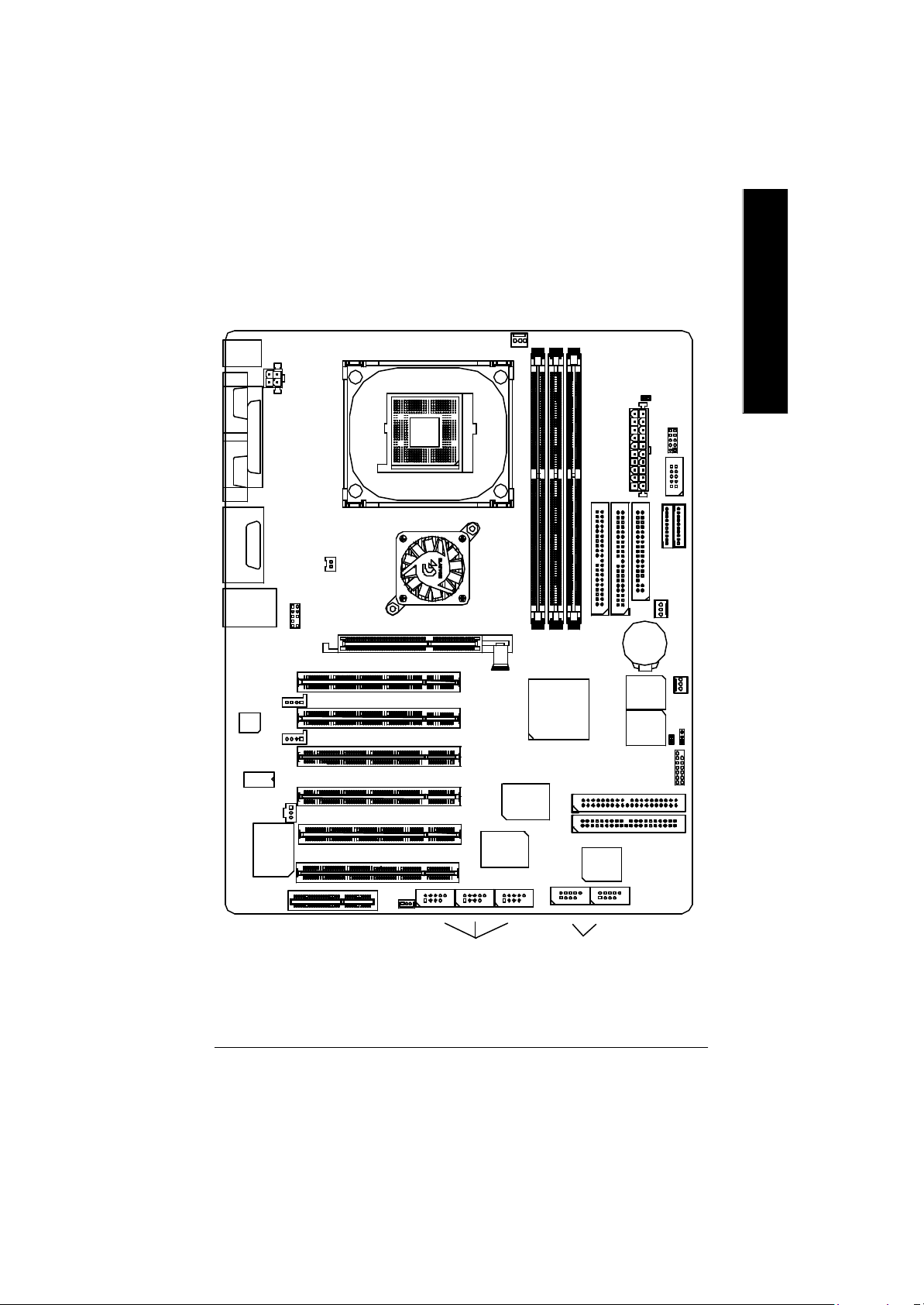
GA-8IEX Series Motherboard Layout
English
KB_ MS
COMA
COMB
LINE_OUT
LINE_IN
MIC_IN
USB
AC97
825 62ET
LPT1
GAME
LAN
CNR(**)
AUX_12V
CT5880
F_AUDIO_I
AGP
CD_IN
A UX_IN
SPDIF
NB-FAN
SOCKET478
GA-8IEX/8IEXP
P4 Titan533
WOL(**)
CPU_FAN
Intel 845E
PCI1
PCI2
PCI3
PCI4
PCI5
PCI6
1394-2
IEEE1394(**)
IT8712
VT6306(**)
1394-31394-1
DDR1
DDR3
DDR2
ICH4
IDE4 (**)
F_ USB2
Front USB 2.0
IDE3 (**)
IDE2
F_ USB1
DIMM_LED_CONN
ATX
IDE1
BATTERY
BAC KUP
BIOS
MAIN
BIOS
PDC20276(**)
IR/CIR
SC
SD(**)
FLOPPY
PWR_FAN
CI
F_PANEL
MS(**)
SYS_FAN
CLR_CMOS
* For GA-8IEX Only. ** For GA-8IEXP Only.
- 7 -
Introduction
Page 8
Chapter 2 Hardw are Installation Process
English
To set up your computer, you must complete the following steps:
Step 1- Install the Centr al Processing Unit (CPU)
Step 2- Install memory modules
Step 3- Install expansion cards
Step 4- Connect ribbon cables, cabinet w ires, and power supply
Step 5- Setup BIOS software
Step 6- Install supporting software tools
Step 2Step1Step4
Step 4
Step 4
Step 4
Step3
- 8 -GA-8IEX Series Motherboard
Page 9
Step 1: Install the Central Processing Unit (CPU)
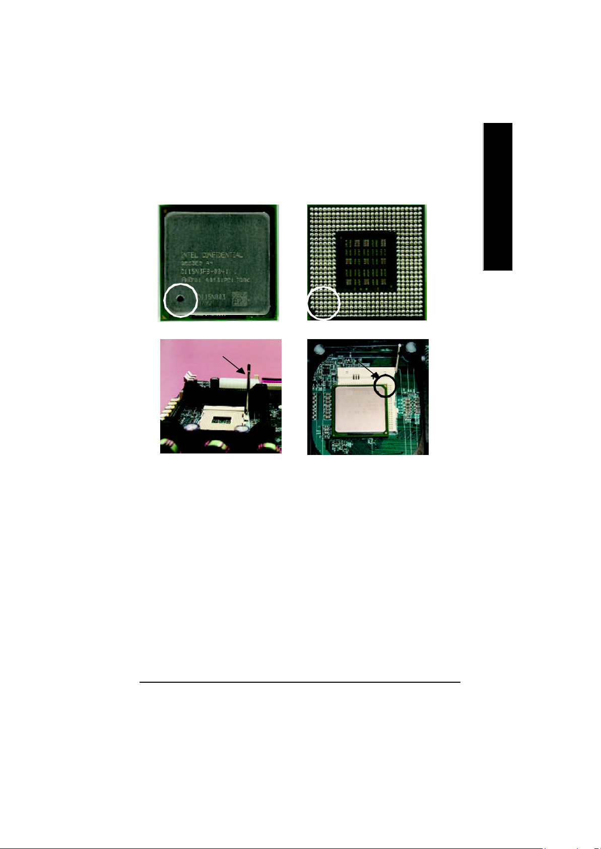
Step 1-1 CPU Instal lation
English
Pin1 indicator
CPU Top View CPU Bottom View
Socket Actuation Lever
1. Pull up the CP U socket lever
and up to 90-degree angle.
3. Press down the CPU socket
lever and finish CPU installation.
M Please make sure the CPU type is supported by the motherboard.
Pin1indicator
Pin1 indicator
2. Locate Pin 1 in the socket and look
for a (golden) cut edge on the CPU
upper corner. Then insert the CPU
into the socket.
M If you do not match the CPU socket Pin 1 and CPU cut edge well, it will cause
improper installation. Please change the insert orientation.
- 9 - Hardware Installation Process
Page 10

Step 1-2 : CPU Heat Sink Installation
English
1. Fasten the heatsink supporting-base
onto the CPU socket on the mainboard.
M Plea se use Intel approved cooling fan.
M We recomme nd you to apply the thermal tape to provide better heat conduction between
your CPU and heats ink.
(The CPU cooling fan might stick to the CPU due to the hardening of the thermal paste.
During this condition if y ou try to remove the cooling fan, you might pull the processor out
of t he CPU socket alone with the cooling fan, and might damage the processor. To avoid
this from happening, we suggest you to either use thermal tape instead of thermal paste, or
remove the cooling fan with extreme caution.)
M Mak e sure the CPU fan power cable is plugged in to the CPU fan connector, this completes
the installa tion.
M Plea se refer to CPU heat sink user’s manual for more detail installation procedure.
2. Make sure the CPU fan is plugged to
the CPU fan connector, than install
complete.
- 10 -GA-8IEX Series Motherboard
Page 11
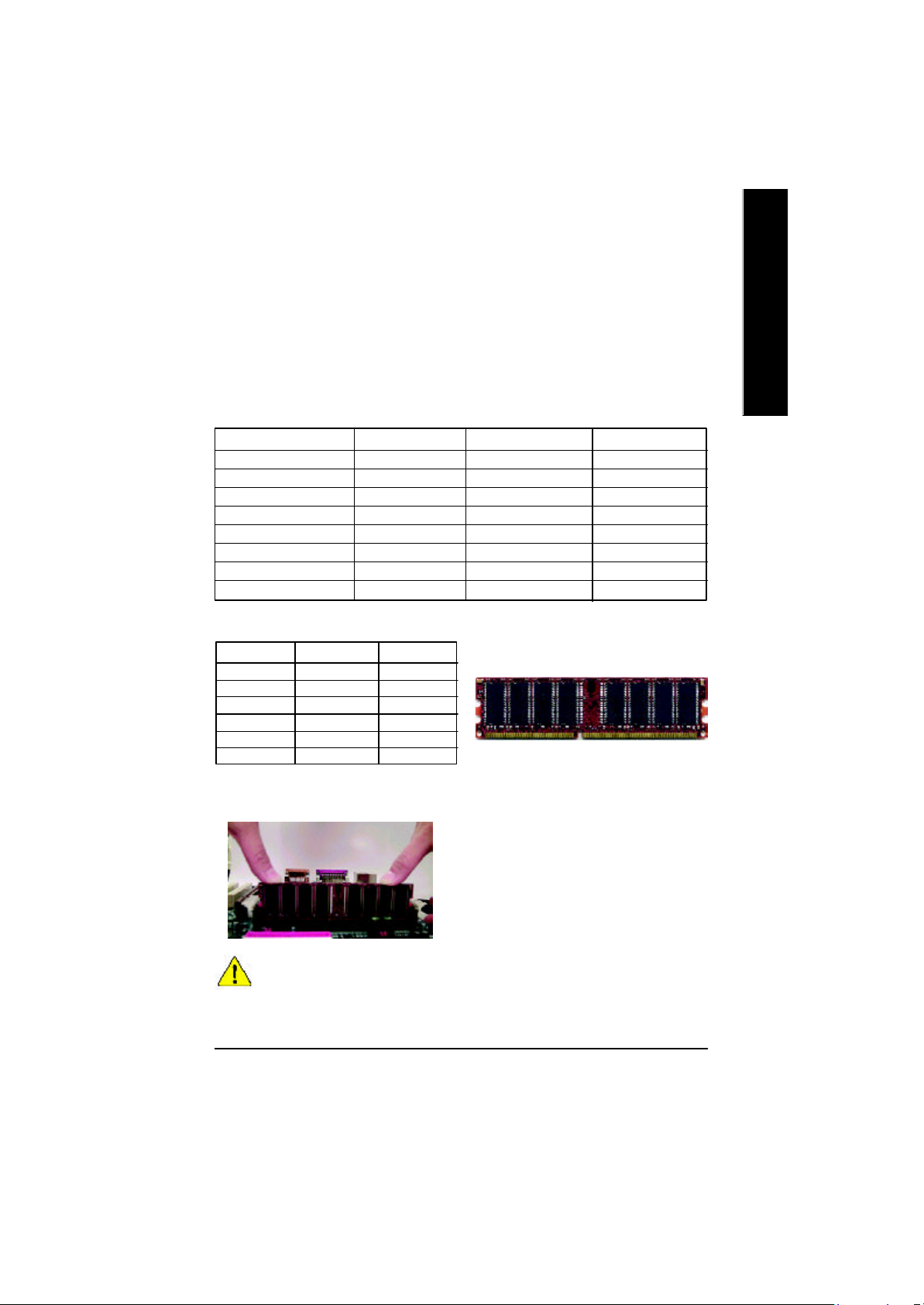
Step 2: Install memory modules
The motherboard has 3 dual inline memory module (DIM M) sockets, but it can only support a
maximum of 4 banks of DDR memory. DDR socket 1 uses 2 banks, DDR socket 2&3 share the
remainin g 2 banks. Please refer to the following tables for possible memory configurations supported. The
BIOS will automatically detects memory type and size. To install the memory module, just push it
vertically into the DIMM Slot .The DIMM module can only fit in one direction due to the notch.
Memory size can vary between sockets.
Total Memory Sizes With Unbuffered DDR DIMM
Dev ices used on DIMM 1 DIMM x 64 / x 72 2 DIMMs x 64 / x 72 3 DIMMs x 64 / x 72
64 Mbit (2Mx 8x4 banks) 128 MBytes 256 MBytes 256 MBytes
64 Mbit (1Mx 16x4 banks) 32 MBy tes 64 MBy tes 96 MBy tes
128 Mbit(4Mx 8x4 banks) 256 MBytes 512 MBytes 512 MBytes
128 Mbit(2Mx 16x4 banks) 64 MBy tes 128 MBytes 196 MBytes
256 Mbit(8Mx 8x4 banks) 512 MBytes 1 GBy tes 1 GBytes
256 Mbit(4Mx 16x4 banks) 128 MBytes 256 MBytes 384 MBytes
512 Mbit(16Mx 8x4 banks) 1 GBy tes 2 GBytes 2 GBytes
512 Mbit(8Mx 16x4 banks) 256 MBytes 512 MBytes 768 MBytes
Notes: Double-sided x 16 DDR memory devices are not support by Intel 845E/G chipset.
DDR1 DDR2 DDR3
S S S
D S S
D D X
D X D
S D X
S X D
D:Double Sided DIMM S:Single Sided DIMM
X:Not Use
1. The DIMM socke t has a notch, so the DIMM memory
module can only fit in one direction.
2. Insert the DIMM memory module vertically into the
DIMM socket. Then push it down.
3. Close the plastic clip at both edges of the DIMM
sockets to lock the DIMM module.
Reverse the installation steps when you wish to
remove the DIMM module.
DDR
English
M When STR/DIMM LED is ON, do not install/remove DIMM from socket.
M Please note that the DIMM module can only fit in one direction due to
the two notches. Wrong orientation will cause improper installation.
Please change the insert orientation.
- 11 - Hardware Installation Process
Page 12
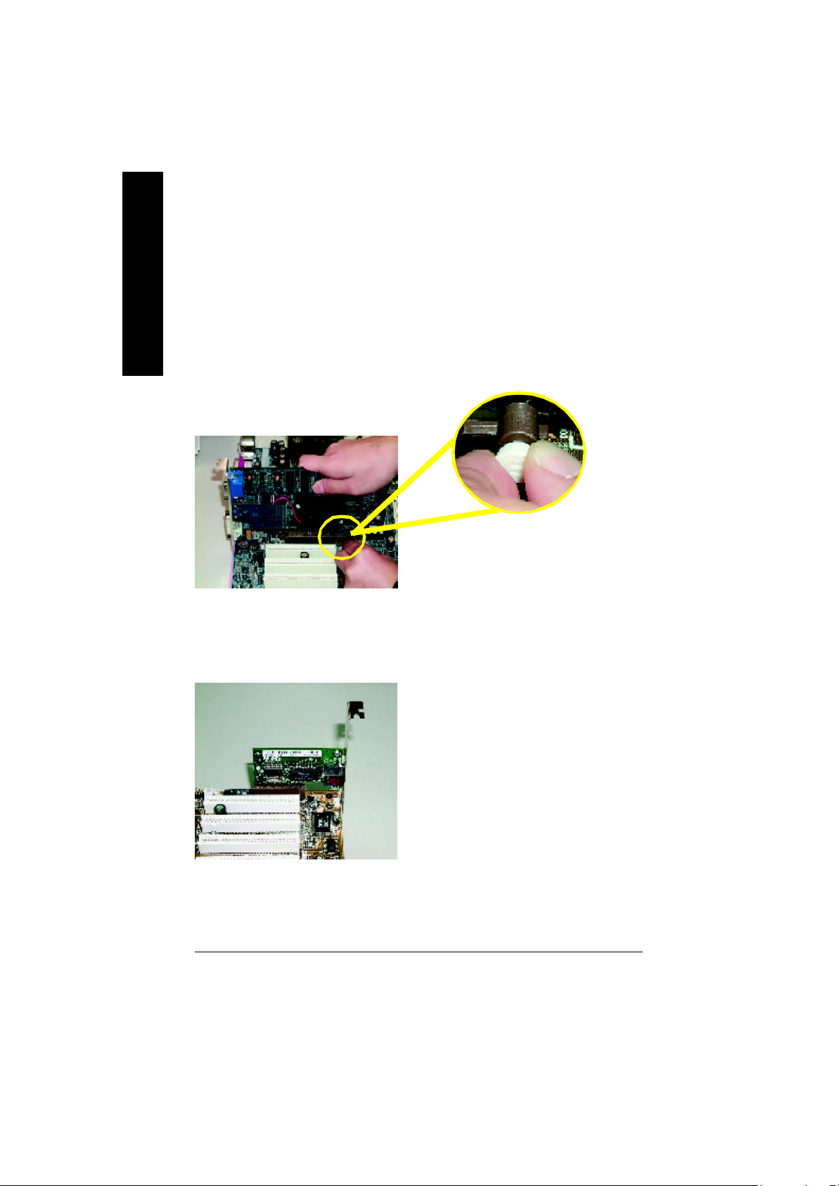
Step 3: Install expansion cards
1. Read the related expansion card’s instruction document before install the expansion card into
English
2. Remove your computer’s chassis cover, necessary screws and slot bracket from the computer.
3. Press the expansion card firmly into expansion slot in motherboard.
4. Be sure the metal contacts on the card are indeed seated in the slot.
5. Replace the screw to secure the slot bracket of the expansion card.
6. Replace your computer’s chassis cover.
7. Power on the computer, if necessary, setup BIOS utility of expansion card from BIOS.
8. Install related driver from the operating system.
Issues To Beware Of When Installing CNR
Please use standard CNR card like the one in order to avoid mechanical problem.
the computer.
AGP Card
Please carefully pull out the small whitedrawable bar at the end of the AGP slot
when you try to install/ Uninstall the AGP
card. Please align the AGP card to the
onboard AGP slot and press firmly down on
the slot .Make sure your AGP card is locked
by the small white- drawable bar.
MPlease note:
If M/B has hardw are audio (CT5880), your modem riser
has been set to "Primary " automatically
Standard CNR Card
- 12 -GA-8IEX Series Motherboard
Page 13
Step 4: Connect ribbon cables, cabinet wires, and power
supply
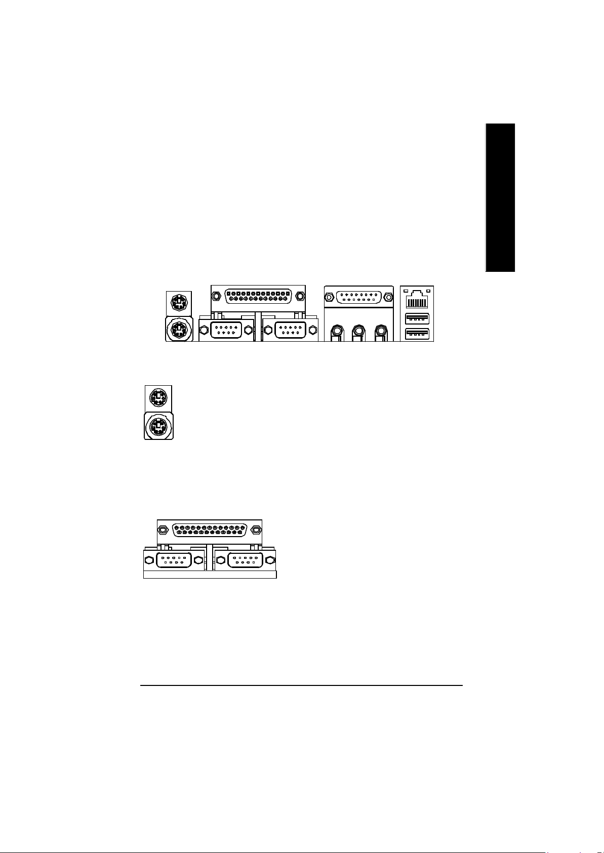
Step 4-1 : I/O Back Panel Introduction
English
u v w
x
u PS/2 Keyboard and PS/2 Mouse Connector
PS/2 Mouse Connector
(6 pin Female)
PS/2 K eyboard Connector
(6 pin Female)
ØThis connector supports standard PS/2
keyboard and PS/2 mouse.
v Parallel Port and Serial Ports (COMA/COMB)
Parallel Port
(25 pin Female)
ØThis connector supports 2 standard COM ports
and 1 Parallel port. Device like printer can be
connected to Parallel port ; mouse and modem
etc can be connected to Serial ports.
y
COMA COMB
Serial Ports (9 pin Male)
- 13 - Hardware Installation Process
Page 14

w Game /MIDI Ports
English
Joystick/ MIDI (15 pin Female)
ØThis connector supports joystick, MIDI keyboard
and other relate audio devices.
x Audio Connectors
Line Out 1
(Line Out 2)
MIC In
Line In
y USB/ LAN Connector
L AN
USB 0
USB 1
Ø After install onboard audio driver, you may connect
speaker to Line Out jack, micro phone to MIC In jack.
Device like CD-ROM , walkman etc can be connected
to Line-In jack.
Please no te: Line Out 1: Line Out or SPDIF (The SPDIF
output is capable of providing digital audio to external
speakers or compressed AC3 data to an external Dolby
digital decoder). To enable SPDIF, simply insert SPDIF
connector into Line Out1. Line Out1 will become SPDIF
Out automatically.
To enable Four Speaker (for Creative 5880 audio only),
and Line In will become Line Out2 to support second
pair of stereo speakers.
If you want the detail information for “ 4 _Channel
Audio & SPDIF “ setup, please download
8I EX Series manual (Complete Version) from
Gigabyte web. http://www.gigabyte.com.tw.
Ø Before you connect your device(s) into USB
connector(s), please make sure your device(s)
such as USB keyboard, mouse, scanner, zip,
speaker..etc. Have a standard USB interface.
Also make sure your OS (Win 95 with USB
supplement, Win98, Windows 2000, Windows
ME, WinNT with SP 6) supports USB controller.
If your OS does not support USB controller,
please contact OS vendor for possible patch or
driver upgrade. For more information please
contact your OS or device(s) vendors.
- 14 -GA-8IEX Series Motherboard
Page 15

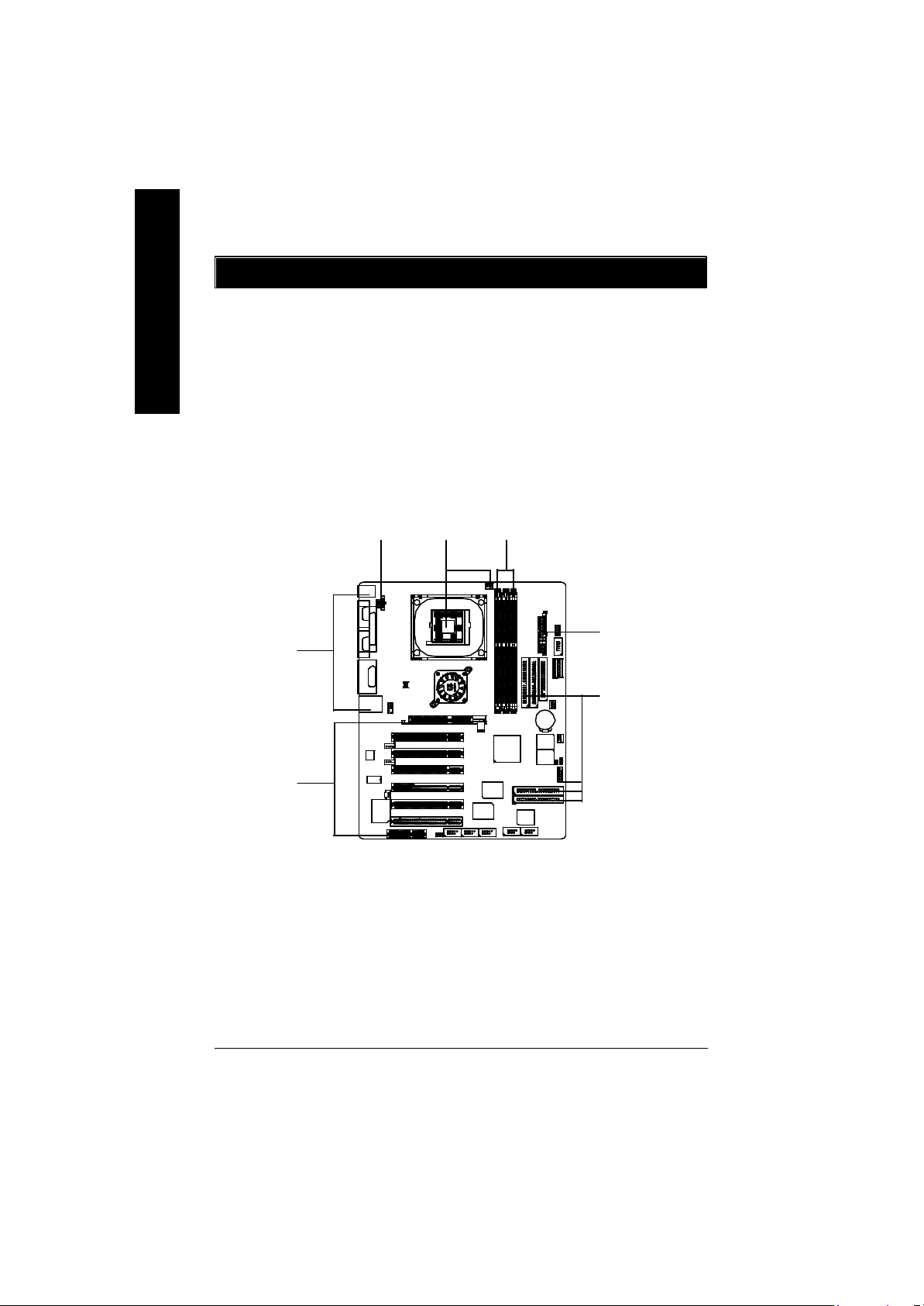
Step 4-2 :Connectors & Jumper Setting Introduction
A B C D
X
English
E
W
V
U
T
S
PFOQR
A) CPU_FAN M) CLR_CMOS
B) BATTERY N) F_P ANEL
C) ATX O) IDE3/IDE4 (**)
D) IR/CIR P) F_USB1/F_USB2
E) SC Q) 1394-1/1394-2/1394-3 (**)
F) MS (**) R) WOL(**)
G) SD (**) S) SPDIF
H) FDD T) AUX_IN
I) IDE1/IDE2 U) CD_IN
J) PWR_FAN V) F_AUDIO_I
K) SYS_FAN W) NB_FAN
L) CI X) AUX_12V
G
H
I
J
K
L
M
N
* For GA-8IEX Only. ** For GA-8IEXP Only.
- 15 - Hardware Installation Process
Page 16

X ) AUX_12V( +12V Power Connector)
English
GND
GND
Ø This connector (ATX +12V) is
used only for CPU Core Voltage.
1
+12V
+12V
234
C) ATX (ATX Power Con nector)
20
5V SB (Stand by +5V)
+12V
Power Good
GND
VCC
GND
VCC
GND
3.3V
3.3V
1
A) CPU_FAN (CPU Fan Connector)
+12V/Control
GND
Sense
1
K) SYS_FAN (System Fan Connector)
1
GND
+12V/Control
Sense
Ø AC power cord should only be connected to
your power supply unit after ATX power
cable and other related dev ices are firmly
VCC
connected to the mainboard.
VCC
-5V
GND
GND
GND
PS-ON(Soft On/Off)
GND
-12V
3.3V
Ø Please note, a proper installation of the CPU
cooler is essential to prevent the CPU from
running under abnormal condition or
damaged by overheating.The CPU fan
connector supports Max. current up to 600mA .
Ø These connector allow you to link with the
cooling fan on the system case to lower the
system temperature.
J) PWR_FAN (Power Fan Connector)
Sense
1
+12V/Control
GND
- 16 -GA-8IEX Series Motherboard
Page 17

W) NB_FAN
Ø If you installed wrong direction, the Chip Fan
will not wo rk. Sometimes will damage the Chip
GND
1
VCC
Fan. (Usually black cable is GND)
English
I,H ) Floppy/ IDE1 / IDE2 Connector
(Primary/Secondary]
1
1
IDE2
1
IDE1
FDD
O) IDE3/IDE4 Connector
(RAID/ATA133,Green Connector)(**)
IDE4
IDE3
1
Ø Important Notice:
Please connect first harddisk to IDE1
and connect CD_ROM to IDE2.
The red stripe of the ribbon cable must be the
same side with the Pin1.
Important Notice:
1. The rad stripe of the ribbn cable must be the
same side with the Pin1.
2. If you wish to use IDE3 and IDE4, please use
it in unity with BIOS (either RAID or ATA133).
Then, install the correct driver to have proper
operation. For details, please refer to
the RAID manual.
If you want the detail information for “RAID“
setup , please download 8IEX Series manual
(Complete Version) from Gigabyte web.
http://www.gigabyte.com.tw.
- 17 - Hardware Installation Process
Page 18

R) WOL(Wake on LAN)(**)
English
1
+5V SB
Ø This connector allows the remove servers to
manage the system that installed this
mainboard via your network adapter which
also supports WOL.
GND
Signal
S)SPDIF
1
VCC
SPDIF Out
GND
SPDIF
U) CD_IN (CD Audio Line In Connector)
CD_R
CD_L
GND
1
T) AUX_IN ( AUX In Connector)
AUX-R
AUX-L
GND
Ø The SPDIF output is capable of providing
digital audio to external speakers or com
pressed AC3 data to an external Dolby
Digital Decoder. U se this feature only when
your stereo system has digital input
function.
Ø Connect CD-ROM or DVD-ROM audio out
to the connector.
Ø Connect other device(such as PCI TV Tunner
audio out )to the connector.
1
* For GA-8IEX Only. ** For GA-8IEXP Only.
- 18 -GA-8IEX Series Motherboard
Page 19

P)F_ USB1 / F_USB2
(Front USB Connector, Y ellow Connector)
USB Dy+
USB Over
GND
Current
USB Dy-
Power
USB Dy+
USB Over
GND
Current
Power
USB Dy-
Ø Be careful with the polarity of the front
panel USB connector. Check the pin
assignment while you connect the front
panel USB cable. Please contact your
nearest dealer for optional front panel
USB cable.
English
1
Power
USB Dx-
USB Dx+
USB2
V) F_AUDIO_I (F_AUDIO Connector)
GND
1
Power
USB1
GND
USB Dx-
USB Dx+
Ø If you want to use Front Audio connector, you
must remove 5-6, 9-10 Jumper.
In order to utilize the front audio header, your
MIC
REF
Front Audio (R)
Reserved
Front Audio (L)
1
GND
POWER
Rear Audio (R)
Rear Audio (L)
chassis must have front audio connector. Also
please make sure the pin assigment on the
cable is the same as the pin assigment on
the MB header. To find out if the chassis you
are buying support front audio connector,
please contact your dealer.
Q) 1394-1/1394-2/1394-3(IEEE1394 Connector,Grey Connector) (**)
Ø Please Note: Serial interface
standard set by Institute of
GND
TPB2-
GND
TPB2+
VCC
VCC
GND
Electrical and Electronics
Engineers , which has fea
tures like high speed, high
bandwidth and hot plug.
GND
VCCVCC
GND
TPA0-
TPB0-
1
GND
TPA0+
TPB0+
1394-1
TPA1-
1
TPA1+
1394-2
TPB1-
GND GND
TPB1+
GND
VCC
VCC
TPA2-
1
TPA2+
1394-3
- 19 - Hardware Installation Process
Page 20

D) IR/CIR (IR/CIR )
English
E) SC(Smart Card Interface,Black Connector)
G)SD(MMC) (Secure Digital Memory Car d Interface,Red exide Connector) (**)
F)MS (Mem ory Stick Interface,White Connector) (**)
SCAPSNT
NC
GND
VCC
CIRRX
NC
SCAC8
SCAL ED
SCARST-
GND
SC
5
1
IRTX
GND
IRRX
NC
VCC
1
SCACL K
SCAIO
SCAC4
SCAPWCTLVCC
Ø Make sure the pin 1 on the IR device is
aling with pin one the connector . To
enable the IR/CIR function on the board,
you are required to purchase an option IR/
CIR module. For detail information please
contact your autherized Giga-Byte
distributor.
To use IR function only, please connect IR
module to Pin1 to Pin5.
Ø The device could be expanded for reading Flash
Memory, such as SD(Security Digital),
MS (Memory Stick) and Smart Card Reader
Connector. The Smart IC Card could
increase security in authenticating online
transactions; the card reader device ( inquire
local distributor) made by Third Party could
be purchased by users.
SD
1 GND
** For GA-8IEXP Only.
SDLED
SDPWCTL-
SDCLK
SD5
SD4
SD3
SD2
VCC3
SD1
MS
MSLED
MSPW CTLMSCLK
MS5
MS4
MS3
MS2
VCC3
MS1
1
- 20 -GA-8IEX Series Motherboard
GND
Page 21

L ) CI
Ø This 2 pin connector allows y our system to
enable or disable the system alarm if the sys
GND
1
Signal
tem case begin remove.
English
M) CLR_CMOS (Clear CMOS)
1-2 close: Clear CMOS
1
2-3 close: Normal
1
B ) BATTERY (Battery)
+
Ø You may clear the CMOS data to its default
values by thisjumper.
Default doesn’t include the “Shunter” to prevent
from improp er use this jumper. To clear CMOS,
temporarily short 1-2 pin.
CAUTION
v Danger of explosion if battery is incorrectly
replaced.
v Replace only with the same or equivalent
type recommended by the manufacturer.
v Dispose of used batteries according to the
manufacturer’s instructions.
- 21 - Hardware Installation Process
Page 22

N) F_P ANEL (2x7 pins connector)
English
13
RS TRST+
SPK+
1
SPK-
HD-
HD (IDE Hard Disk Active LED) Pin 1: LED anode(+)
SPK (S peaker Connector) Pin 1: VCC(+)
RST (Reset Switch) Open: Normal Operation
PD+/PD_G-/PD_ Y-(Power LED) Pin 1: LED anode(+)
PW (Soft Power Connector) Open: Normal Operation
PW+
PW-
PD+
PD_GPD_Y-
1
HD+
1
2 14
Pin 2: LED cathode(-)
Pin 2- Pin 3: NC
Pin 4: Data(-)
Close: Reset Hardware System
Pin 2: LED cathode(-)
Pin 3: LED cathode(-)
Close: Power On/Off
Ø Please connect the power LED, PC speaker, reset switch and power switch etc of your chassis
front panel to the F_PANEL connector according to the pin assignment above.
- 22 -GA-8IEX Series Motherboard
Page 23

Chapter 3 BIOS Setup
BIOS Setup is an overview of the BIOS Setup Program. The program that allows users to modify
the basic system configuration. This type of information is stored in battery-backed CMOS RAM so
that it retains the Setup information when the power is turned off.
ENTERING SETUP
Powering O N the computer and pressing <Del> immediately will allow you to enter Setup. If you
require more advanced BIOS settings, please go to “Adv anced BIOS” setting menu.To enter Advanced BIOS setting menu, press “Ctrl+F1” key on the BIOS screen.
GETTING HELP
M ain Menu
The on-line description of the highlighted setup function is displayed at the bottom of the screen.
Status Page Setup Menu / Option Page Setup Menu
Press F1 to pop up a small help window that describes the appropriate keys to use and the possible
selections for the highlighted item. To exit the H elp Window press <E sc>.
The Main Menu
Once you enter Award BIOS CMOS Setup Utility, the Main M enu will appear on the screen. The
Main Menu allows you to select from eight setup functions and two exit choices. Use arrow keys to
select among the items and press <Enter> to accept or enter the sub-menu.
Dual BIOS / Q-Flash Utility
After power on the computer, pressing <Del> immediately during POST (Power On Self Test) it
will allow you to enter Award BIOS CMOS SETUP, then press <F8> to enter DualBIOS/Q-Flash
utility. If you want to detail information for “DualBIOS/Q-Flash Utility “, please download
this manual from Gigabyte web http://www.gigabyte.com.tw.
English
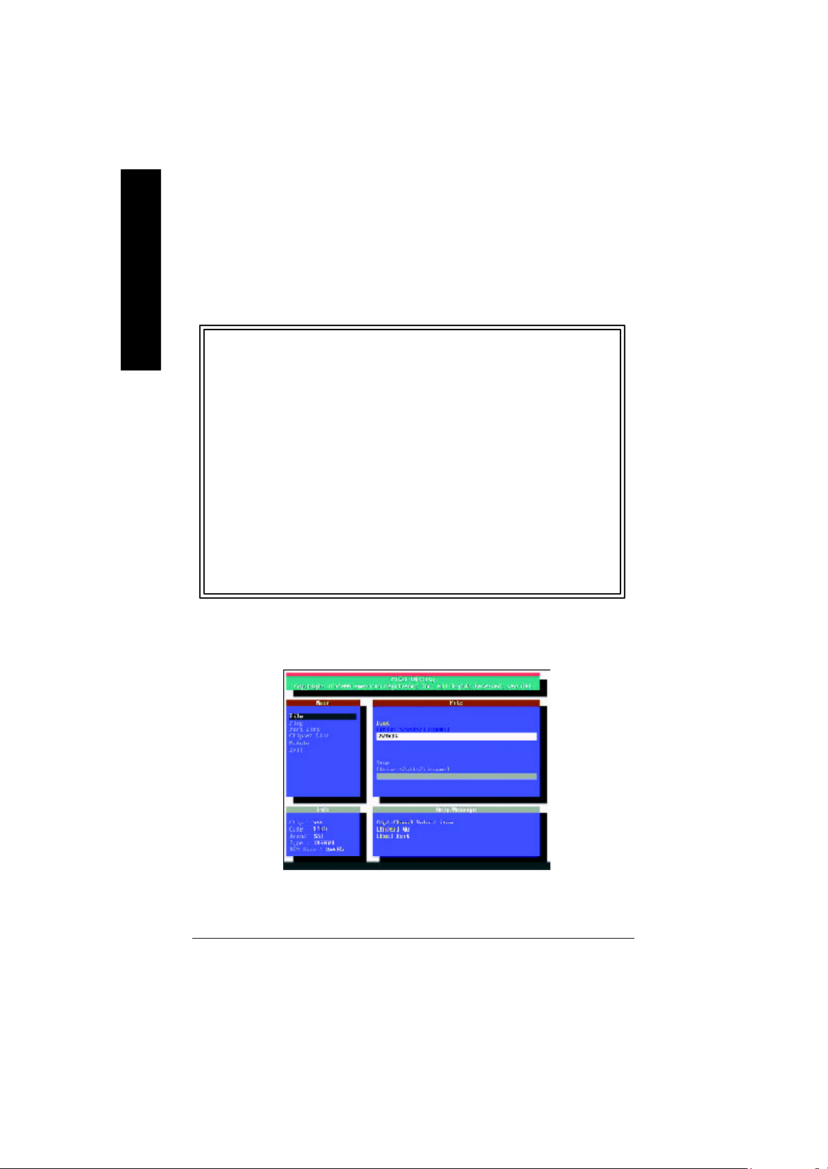
Select Language
You can press <F3> to select multi language. There are 7 languages available, including
English, Japanese, French, Spanish, Germany, Simplified Chinese, Traditional Chinese.
CMOS Set up Utility-Copyright (C) 198 4-2002 Award Software
}Standa rd CMOS Features Select Language
}Advanced BIOS Fe atures Load Fail-Safe Defaults
}Integrated Peripherals Load Optimized Defaults
}Power Manag ement Setup Set Supervi sor Password
}PnP/PCI Con figurations Set User Password
}PC Health Status Save & Exit Setup
}Freque ncy/Voltage Control Exit With out Saving
Top Performance
- 23 - BIOS Setup
u
Page 24

l Stand ard CMOS Features
l Advanc ed BIOS Features
English
l Advance d Chipset Features
l Integrated Peri pherals
l Pow er Management Setup
l PnP/PCI Confi gurations
l PC H ealth Status
l Fr equency/Voltage Control
l Top Performance Defaul ts
l Sel ect Language
l Load Fail-Safe Defaults
This setup page includes all the items in standard compatible BIOS.
This setup page includes all the items of Award special enhanced features.
This setup page includes all the items of chipset special features.
We would not suggest you change the chipset default setting unless you really
need it.
This setup page includes all onboard peripherals.
We would not suggest you change the default setting unless you really need it.
For power End-User use only.
This setup page includes all the items of Green function features.
We would not suggest you change the default setting unless you really need it.
For power End-User use only.
This setup page includes all the configurations of PCI & PnP ISA resources.
We would not suggest you change the default setting unless you really need it.
For power End-User use only.
This setup page is the System auto detect Temperature, voltage, fan, speed.
This setup page is control CPU’s clock and frequency ratio.
For power End-User use only.
Top Performance Defaults indicates the value of the system parameters which the system
would be in best performance configuration.
This setup page is select multi language.
Fail-Safe Defaults indicates the value of the system parameters which the system w ould
be in safe configuration.
- 24 -GA-8IEX Series Motherboard
Page 25

l Load Op timized Defaul ts
Optimized Defaults indicates the value of the system parameters which the system would
be in best performance configuration.
l Se t S upervisor p assword
Change, set, or disable password. It allows you to limit access to the sy stem and Setup,
or just to Setup.
l Se t User password
Change, set, or disable password. It allows you to limit access to the system.
l Save & Exit Setup
Save CMOS value settings to CMOS and exit setup.
l Exit Wi thout Saving
Abandon all CMOS value changes and exit setup.
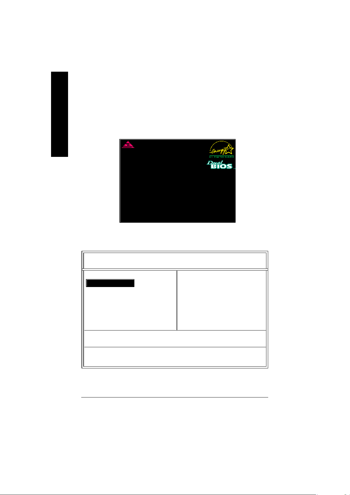
Load Optim ized Default
CMOS Set up Utility-Copyright (C) 198 4-2002 Award Software
}Standa rd CMOS Features Select Language
}Advanced BIOS Fe atures Load Fail-Safe Defaults
}Integrated Peripherals Load Optimized Defaults
}Power Manag ement Setup Set Supervi sor Password
}PnP/PCI Con figurations Set User Password
}PC Health Status Save & Exit Setup
}Freque ncy/Voltage Control Exit With out Saving
Top Performance
Load Optimized Defaults? (Y/N)?Y
English
F Load Optimized Defaults
Selecting this field loads the factory defaults for BIOS and Chipset Features which the
system automatically detects.
To Load Optimized, move cursor, by pressing the arrow keys on the keyboard ,to highlight
the optimized default and press enter key then press "Y" if you decide to load this option.
- 25 - BIOS Setup
Page 26

Save & Exit Setup
CMOS Set up Utility-Copyright (C) 198 4-2002 Award Software
English
F To save exit the BIOS setting screen press F10, and press "Y" if
}Standa rd CMOS Features Select Language
}Advanced BIOS Fe atures Load Fail-Safe Defaults
}Integrated Peripherals Load Optimized Defaults
}Power Manag ement Setup Set Supervi sor Password
}PnP/PCI Con figurations Set User Password
}PC Health Status Save & Exit Setup
}Freque ncy/Voltage Control Exit With out Saving
Top Performance
SAVE to CMOS and EXIT (Y/N)?Y
you want to save setting. By typing "N" or "ESC" will take you
back to setup screen.
If you want the detail informatio n for BIOS setup, please download
8IEXP (Complete Version) manual from Gigabyte web.
http://www.gigabyte.com.tw.
- 26 -GA-8IEX Series Motherboard
Page 27

Revi sion History
Chapter 4 Driver Installation
Picture below are shown in Windows XP (IUCD driver version 2.0)
Insert the driver CD-title that came with your motherboard into your C D-ROM driver, the driver
CD-title will auto start and show the installation guide. If not, please double click the CD-ROM
device icon in "My computer", and execute the setup.exe.
A. Installing Intel 845-E Chipset Driver
Please install this driver as the first priority .
this item installs the chipset driv er utility that
enableds Plug-n-Plag INF support for Intel
chipset component.
B. Installing Sound Driver
Click this item to install sound driv er.
C. Installing LAN Driver
Click this item to install LAN driv er.
If you want the detail information for Driver installation, please download 8IEXP (Complete Version) manual from Gigabyte web.
http://www.gigabyte.com.tw.
Before the end of May 2002, Intel® didn’t announce ICH4 USB2.0 driver.
We’ll put the driver on GIGABYTE’s website asap. (http://www.gigabyte.com.tw).
Please go to the website to get detail information.
English
Appendix A: Intel 845-E Chipset Driver Installation
Follow the setup that show ing on the scween to install the Utility.
Inorder to install the driver successfully, please refer to the following installation procedures.
j
l
k
m
**
** For GA-8IEXP Only.
n
o
- 27 - Driv er Installation
**
**
**
Page 28

Appendix B: Creative CT5880 Sound Driver
Press "Audio" icon.
English
Appendix C: Intel 82562 Network Driver
If you would like to manually install LAN driver, please refer to “Driver
Information” or download 8IEXP (Complete V ersion) manual from
Gigabyte web. http://www.gigabyte.com.tw.
1.Click "Creative CT5880 Sound Driver"
item.
Press "Network" icon.
Click "Driver Information".
- 28 -GA-8IEX Series Motherboard
Page 29

Chapter 5 BIOS Flash Procedure
BIOS update procedure:
Method 1:
If your OS is Win9X, we recommend that you used Gigabyte @BIOSTM Program to flash BIOS.
English
Press "Tools" icon.
1.Click "Gigabyte Utilities".
(1)
Click "P".
Methods and steps:
I. Update BIOS through Internet
a. Click "Internet Update" icon
b. Click "Update New BIOS" icon
c. Select @BIOSTM sever ("Gigabyte @BIOSTM sever 1 in Taiwan" and "Gigabyte
@BIOSTM sever 2 in Taiwan" are available for now, the others w ill be completedsoon)
d. Select the ex act model name on your motherboard
e. System will automatically download and update the BIOS.
Click here.
(3)
2.Click "@BIOS Writer Utility
v.1.08q".
(2)
- 29 - BIOS Flash Procedure
Page 30

II. Update BIOS NOT through Internet:
English
III. Save BIOS
IV. Check out supported motherboard and Flash ROM:
Note:
a. Do not click "Internet Update" icon
b. Click "Update New BIOS"
c. Please select "All Files" in dialog box while opening the old file.
d. Please search for BIOS unzip file, downloading from internet or any other methods (such
as: 8IEXP.F1).
e. Complete update process following the instruction.
In the very beginning, there is "Save Current B IOS" icon shown in dialog box. It means to save
the current BIOS version.
In the very beginning, there is "About this program" icon shown in dialog box. It can help you
check out which kind of motherboard and which brand of Flash ROM are supported.
a. In method I, if it shows two or more motherboard's model names to be selected, please
make sure your motherboard's model name again. Selecting wrong model name will
cause the system unbooted.
b. In method II, be sure that motherboard's model name in BIOS unzip file are the same as
your motherboard's. Otherwise, your sy stem won't boot.
c. In method I, if the BIOS file you need cannot be found in @BIOSTM server, please go onto
Gigabyte' s web site for downloading and updating it according to method II.
d. Please note that any interruption during updating will cause sy stem unbooted
- 30 -GA-8IEX Series Motherboard
Page 31

Method 2:
We use GA-7VTX motherboard and Flash841 BIOS flash utility as example.
Please flash the BIOS according to the following procedures if you are now under the DOS mode.
Flash BIOS Procedure:
STEP 1:
(1) Please make sure your system has installed the extraction utility such as winzip or pkunzip.
Firstly you have to install the extraction utility such as winzip or pkunzip for unzip the files. Both
of these utilities are available on many shareware download pages like
http://www.shareware.cnet.com
STEP 2: Make a DOS boot diskette. (See example: Windows 98 O.S.)
Beware: Windows ME/2000 are not allowed to make a DOS boot diskette.
(1) With an available floppy disk in the floppy drive. Please leave the diskette "UN-write protected"
type. Double click the "My Computer" icon from Desktop, then click " 3.5 diskette (A)" and right
click to select "Format (M)"
English
- 31 - BIOS Flash Procedure
Page 32

(2) Select the "Quick (erase)" for Format Type, and pick both "Display summary when finished" and
English
(3) After the floppy has been formatted completely, please press "Close".
"Copy system files", after that press "Start". That w ill format the floppy and transfer the needed
system files to it.
Beware: This procedure will erase all the prior data on that floppy, so please proceed accordingly.
- 32 -GA-8IEX Series Motherboard
Page 33

STEP 3: Download BIOS and BIOS utility program.
(1) Please go to Gigabyte website http://www.gigabyte.com.tw/index.html, and click "Support".
(2) From Support zone, click the "Motherboards BIOS & Drivers".
English
- 33 - BIOS Flash Procedure
Page 34

(3) We use GA-7VTX motherboard as example. Please select GA-7VTX by Model or Chipset
English
(4) Select an appropriate BIOS version (For example: F4), and click to download the file. It will pop
optional menu to obtain BIOS flash files.
up a file download screen, then select the "O pen this file from its current location" and press
"OK".
- 34 -GA-8IEX Series Motherboard
Page 35

(5) At this time the screen shows the following picture, please click "Extract" button to unzip the
files.
(6) Please extract the download files into the clean bootable floppy disk A mentioned in STEP 2,
and press "Extract".
English
- 35 - BIOS Flash Procedure
Page 36
STEP 4: Make sure the system will boot from the floppy disk.
(1) Insert the floppy disk (contains bootable program and unzip file) into the floppy drive A. Then,
English
(2) Once you enter the BIOS setup utility, the main menu will appear on the screen. Use the arrows
restart the system. The system will boot from the floppy disk. Please press <DEL> key to enter
BIOS setup main menu when system is boot up.
American Release:09/16/99
Megatrends AMI BIOS (C) 19 99 American Megatr end
7VTX F1
Check Syste m Health OK
AMD-Athlon(tm)Proce ssor-900MHz
Checking NVRAM...
262144KB
Wai t...
Press F1 to ente r Dual BIOS Utility. Press ESC to quit
Press any key to contiune
( C ) American Megatrends Inc.,
63-000 1-001199-00101111-071595-VIA_K7-GA7VTX1-F
to highlight the item "BIOS FEATURES SETUP".
AMIBIOS SIMPLE SETUP UTILITY - VERSION 1.24b
(C) 1999 American Megatrends, Inc. All Rights Reserv ed
STANDARD CMOS SETUP INTEGRATED PERIPHERALS
BIOS FEATURES SETUP HARDWARE MONITOR & MISC SETUP
CHIPSET FEATURES SETUP SUPERVISOR PASSWORD
POWER MANAGEMENT SETUP USER PASSWORD
PNP / PCI CONFIGURATION IDE HDD AUTO DETECTION
LOAD BIOS DEFAULTS SAVE & EXIT SETUP
LOAD SETUP DEFAULTS EXIT WITHOUT SAVING
ESC: Quit hifg : Select Item (Shift)F2 : Change Color F5: Old Values
F6: Load BIOS Defaults F7: Load Setup Defaults F10:Sav e & Exit
Time, Date , Hard Disk Type…
- 36 -GA-8IEX Series Motherboard
Page 37

(3) Press "Enter" to enter "BIOS FEATURES SETUP" menu. Use the arrows to highlight the item
"1st Boot Device", and then use the "Page Up" or "Page Down" keys to select "Floppy".
AMIBIOS SETUP - BIOS FEATURES SETUP
( C ) 2001 American Megatrends, Inc. All Rights Reserv ed
1st Boot Dev ice : Floppy
2nd Boot Dev ice : IDE-0
3rd Boot Dev ice : CDROM
S.M.A.R.T. for Hard Disks : Disabled
BootUp Num-Lock : On ESC: Quit hifg: Select Item
Floppy Drive Seek : Disabled F1 : Help PU/PD/+/- : Modify
Password Check : Setup F5 : Old Values (Shift)F2: Color
F6 : Load BIOS Defaults
F7 : Load Setup Defaults
(4) Press "ESC" to go back to previous screen. Use the arrows to highlight the item "SAVE & EXIT
SETUP" then press "Enter". System wi ll ask "SAVE to CMOS and EXIT (Y/N)?" Press "Y" and
"Enter" keys to confirm. Now the system will reboot automatically, the new BIOS setting will be
taken effect next boot-up.
AMIBIOS SIMPLE SETUP UTILITY - VERSION 1.24b
(C) 2001 American Megatrends, Inc. All Rights Reserv ed
STANDARD CMOS SETUP INTEGRATED PERIPHERALS
BIOS FEATURES SETUP HARDWARE MONITOR & MISC SETUP
CHIPSET FEATURES SETUP SUPERVISOR PASSWORD
POWER MANAGEMENT SETUP USER PASSWORD
PNP / PCI CONFIGURATION IDE HDD AUTO DETECTION
LOAD BIOS DEFAULTS SAVE & EXIT SETUP
LOAD SETUP DEFAULTS EXIT WITHOUT SAVING
ESC: Quit hifg : Select Item (Shift)F2 : Change Color F5: Old Values
F6: Load BIOS Defaults F7: Load Setup Defaults F10:Sav e & Exit
Save to CMOS and EXIT (Y/N)? Y
English
Save Data to CMOS & Ex it SETUP
- 37 - BIOS Flash Procedure
Page 38
STEP 5: BIOS flashing.
(1) After the system boot from floppy disk, type "A:\> dir/w" and press "Enter" to check the entire
English
(2) Now screen appears the following Flash Utility main menu. Press "Enter", the highlighted item
files in floppy A. Then type the "BIOS flash utility" and "BIOS file" after A:\>. In this case you
have to type "A:\> Flash841 7VTX.F4" and then press "Enter".
Starting Windows 98…
Microsoft(R) Windows98
© Copyright Microsoft Corp 1981-1999
A:\> dir/w
Volume in drive A has no label
Volume Serial Number is 16EB-353D
Directory of A:\
COMMAND.COM 7VTX.F4 FLASH84 1.EXE
3 file(s) 838,954 bytes
0 dir(s) 324,608 bytes free
A:\> Flash841 7VTX.F4
will locate on the model name of the right-upper screen. Right after that, press "Enter" to start
BIOS Flash Utility.
- 38 -GA-8IEX Series Motherboard
Page 39

(3) It will pop up a screen and asks "Are you sure to flash the BIOS?" Press [Enter] to continue the
procedure, or press [ESC] to quit.
Beware: Please do not turn off the system while you are upgrading BIOS. It will render your
BIOS corrupted and system totally inoperative.
Are you sure to flash the BIOS?
[Enter] to continue Or [Esc] to cancel?
(4) The BIOS flash completed. Please press [ESC] to exit Flash Utility.
English
EXIT?
[Enter] to continue Or [Esc] to cancel?
- 39 - BIOS Flash Procedure
Page 40

STEP 6: Load BIOS defaults.
Normally the system redetects all devices after BIOS has been upgraded. Therefore, we highly
recommend reloading the BIOS defaults after BIOS has been upgraded. This important step resets
English
everything after the flash.
(1) Take out the floppy diskette from floppy drive, and then restart the system. The boot up screen
` will indicate your motherboard model and current BIOS version.
(2) Don't forget to press <DEL> key to enter BIOS setup again when system is boot up. Use the
American Release:09/16/99
Megatrends AMI BIOS (C) 19 99 American Megatr end
7VTX F4
Check Syste m Health OK
AMD-Athlon(tm)Proce ssor-900MHz
Checking NVRAM...
262144KB
Wai t...
Press F1 to ente r Dual BIOS Utility. Press ESC to quit
Press any key to contiune
( C ) American Megatrends Inc.,
63-000 1-001199-00101111-071595-VIA_K7-GA7VTX1-F
arrows to highlight the item "LOAD SETUP DEFAULTS" then press "Enter". System will ask
"Load Setup Defaults (Y/N)?" Press "Y" and "Enter" keys to confirm.
AMIBIOS SIMPLE SETUP UTILITY - VERSION 1.24b
(C) 2001 American Megatrends, Inc. All Rights Reserv ed
STANDARD CMOS SETUP INTEGRATED PERIPHERALS
BIOS FEATURES SETUP HARDWARE MONITOR & MISC SETUP
CHIPSET FEATURES SETUP SUPERVISOR PASSWORD
POWER MANAGEMENT SETUP USER PASSWORD
PNP / PCI CONFIGURATION IDE HDD AUTO DETECTION
LOAD BIOS DEFAULTS SAVE & EXIT SETUP
LOAD SETUP DEFAULTS EXIT WITHOUT SAVING
ESC: Quit hifg : Select Item (Shift)F2 : Change Color F5: Old Values
F6: Load BIOS Defaults F7: Load Setup Defaults F10:Sav e & Exit
Load Setup Defaults? (Y/N )?N
Load Setup Defaults
- 40 -GA-8IEX Series Motherboard
Page 41

(3) Use the arrows to highlight the item "SAVE & EXIT SETUP" and press "Enter". System will ask
"SAVE to CMOS and EXIT (Y/N)?" Press "Y" and "Enter" keys to confirm. Now the system will
reboot automatically, the new BIOS setting will be taken effect next boot-up.
AMIBIOS SIMPLE SETUP UTILITY - VERSION 1.24b
(C) 2001 American Megatrends, Inc. All Rights Reserv ed
STANDARD CMOS SETUP INTEGRATED PERIPHERALS
BIOS FEATURES SETUP HARDWARE MONITOR & MISC SETUP
CHIPSET FEATURES SETUP SUPERVISOR PASSWORD
POWER MANAGEMENT SETUP USER PASSWORD
PNP / PCI CONFIGURATION IDE HDD AUTO DETECTION
LOAD BIOS DEFAULTS SAVE & EXIT SETUP
LOAD SETUP DEFAULTS EXIT WITHOUT SAVING
ESC: Quit hifg : Select Item (Shift)F2 : Change Color F5: Old Values
F6: Load BIOS Defaults F7: Load Setup Defaults F10:Sav e & Exit
Save to CMOS and EXIT (Y/N)? Y
Save Data to CMOS & Ex it SETUP
(4) Congratulate you have accomplished the BIOS flash procedure.
English
- 41 - BIOS Flash Procedure
 Loading...