

Gigabyte GA-8IE2004-L, GA-8IE2004 User Manual [ru]
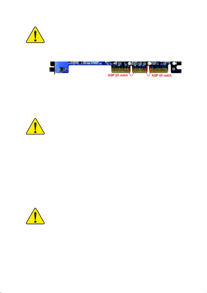
When you installing AGP card, please make sure the following
notice is fully understood and practiced. If your AGP card has "AGP
4X notch"(show below), please make sure your AGP card is AGP 4X
(1.5V).
Caution: AGP 2X card is not supported by Intel® 845(GE/PE) / 845(E/
G) / 850(E) / E7205 / 865(G/PE/P) / 875P. You might experience system
unable to boot up normally. Please insert an AGP 4X/8X card.
Example 1: Diamond Vipper V770 golden finger is compatible with 2X/4X
mode AGP slot. It can be switched between AGP 2X(3.3V) or 4X (1.5V) mode
by adjusting the jumper. The factory default for this card is 2X (3.3V). If you
install this card in GA-8IE2004 Series (or any AGP 4X/8X only) motherboards
without switching the jumper to 4X mode (1.5V), it will burn the motherboard.
Example 2: Some ATi Rage 128 Pro graphics cards made by "Power Color",
the graphics card manufacturer & some SiS 305 cards, their golden finger is
compatible with 2X/4X mode AGP slot, but they support 2X (3.3V) only. If you
install this card in GA-8IE2004 Series (or any AGP 4X/8X only) motherboards,
it will burn the motherboard.
Note : Although Gigabyte's AG32S(G) graphics card is based on ATi Rage
128 Pro chip, the design of AG32S(G) is compliance with AGP 4X (1.5V)
specification. Therefore, AG32S(G) will work fine with Intel® 845(GE/PE) / 845
(E/G) / 850(E) / E7205 / 865(G/PE/P) / 875P based motherboards.
The author assumes no responsibility for any errors or
omissions that may appear in this document nor does
the author make a commitment to update the informa-
tion contained herein.
Third-party brands and names are the property of their
respective owners.
Please do not remove any labels on motherboard, this
may void the warranty of this motherboard.
Due to rapid change in technology, some of the
specifications might be out of date before publication
of this booklet.

Ausschlager Weg 41, 1F, 20537 Hamburg, Germany
( description of the apparatus, system, installation to which it refers)
(reference to the specification under which conformity is declared)
in accordance with 89/336 EEC-EMC Directive
EN 55011 Limits and methods of measurement
EN 55013
EN 55014 Limits and methods of measurement
EN 55015 Limits and methods of measurement
EN 55020
77
7 EN 55022 Limits and methods of measurement
77
DIN VDE 0855
part 10
part 12
77
7 CE marking
77
EN 60065
EN 60335
of radio disturbance characteristics of
industrial, scientific and medical (ISM
high frequency equipment
Limits and methods of measurement
of radio disturbance characteristics of
broadcast receivers and associated
equipment
of radio disturbance characteristics of
household electrical appliances,
portable tools and similar electrical
apparatus
of radio disturbance characteristics of
fluorescent lamps and luminaries
Immunity from radio interference of
broadcast receivers and associated
equipment
of radio disturbance characteristics of
information technology equipment
Cabled distribution systems; Equipment
for receiving and/or distribution from
sound and television signals
The manufacturer also declares the conformity of above mentioned product
with the actual required safety standards in accordance with LVD 73/23 EEC
Safety requirements for mains operated
electronic and related apparatus for
household and similar general use
Safety of household and similar
electrical appliances
(Stamp)
Declaration of Conformity
We, Manufacturer/Importer
(full address)
G.B.T. Technology Trading GMbH
declare that the product
Mother Board
GA-8IE2004 / GA-8IE2004-L
is in conformity with
..
EN 61000-3-2*
77
7 EN 60555-2
77
EN 61000-3-3* Disturbances in supply systems cause
77
7 EN 60555-3
77
77
7 EN 50081-1
77
77
7 EN 50082-1
77
EN 55081-2
EN 55082-2
ENV 55104
EN50091-2
(EC conformity marking)
EN 60950
EN 50091-1
Manufacturer/Importer
Date : Aug. 1, 2003
Disturbances in supply systems cause
by household appliances and similar
electrical equipment “Harmonics”
by household appliances and similar
electrical equipment “Voltage fluctuations”
Generic emission standard Part 1:
Residual commercial and light industry
Generic immunity standard Part 1:
Residual commercial and light industry
Generic emission standard Part 2:
Industrial environment
Generic emission standard Part 2:
Industrial environment
lmmunity requirements for household
appliances tools and similar apparatus
EMC requirements for uninterruptible
power systems (UPS)
Safety for information technology equipment
including electrical bussiness equipment
General and Safety requirements for
uninterruptible power systems (UPS)
Signature:
Name:
Timmy Huang
Timmy Huang

DECLARATION OF CONFORMITY
Per FCC Part 2 Section 2.1077(a)
Responsible Party Name:
Address:
Phone/Fax No:
hereby declares that the product
Product Name:
Model Number:
Conforms to the following specifications:
FCC Part 15, Subpart B, Section 15.107(a) and Section 15.109(a),
Class B Digital Device
Supplementary Information:
This device complies with part 15 of the FCC Rules. Operation is
subject to the following two conditions: (1) This device may not
cause harmful and (2) this device must accept any inference received,
including that may cause undesired operation.
Representative Person’s Name:
Signature:
G.B.T. INC. (U.S.A.)
17358 Railroad Street
City of Industry, CA 91748
(818) 854-9338/ (818) 854-9339
Motherboard
GA-8IE2004 / GA-8IE2004-L
ERIC LU
Eric Lu
Date:
Aug. 1, 2003

GA-8IE2004 Series
P4 Titan Series Motherboard
USER'S MANUAL
Pentium® 4 Processor Motherboard
Rev. 1001
12ME-8IE2004-1001

Table of Content
English
Item Checklist ......................................................................................... 4
WARNING! ...............................................................................................4
Chapter 1 Introduction ............................................................................5
Chapter 2 Hardware Installation Process ............................................. 11
Features Summary ...................................................................................... 5
GA-8IE2004 Series Motherboard Layout .................................................... 7
Block Diagram ............................................................................................. 8
Step 1: Install the Central Processing Unit (CPU)..................................... 12
Step 1-1: CPU Installation .............................................................................................. 12
Step 1-2: CPU Heat Sink Installation ............................................................................ 13
Step 2: Install Memory Modules ................................................................ 14
Step 3: Install expansion cards ................................................................. 16
Step 4: Connect ribbon cables, cabinet wires and ................................... 17
power supply .................................................................................. 17
Step 4-1: I/O Back Panel Introduction ........................................................................... 17
Step 4-2: Connectors Introduction ................................................................................. 19
Chapter 3 BIOS Setup ......................................................................... 31
The Main Menu (For example: BIOS Ver. : E2) ........................................ 32
Standard CMOS Features......................................................................... 34
Advanced BIOS Features .......................................................................... 37
Integrated Peripherals .............................................................................. 39
Power Management Setup ....................................................................... 43
GA-8IE2004 Series Motherboard
- 2 -

PnP/PCI Configurations ............................................................................. 46
PC Health Status........................................................................................ 47
Frequency/Voltage Control ........................................................................ 49
Top Performance ...................................................................................... 51
Load Fail-Safe Defaults ............................................................................. 52
Load Optimized Defaults ........................................................................... 53
Set Supervisor/User Password .................................................................. 54
Save & Exit Setup ....................................................................................... 55
Exit Without Saving ................................................................................... 56
Chapter 4 Technical Reference ........................................................... 59
@BIOS™ Introduction................................................................................. 59
™
EasyTune
Flash BIOS Method Introduction............................................................... 61
2- / 4- / 6-Channel Audio Function Introuction .......................................... 65
Jack-Sensing Introuction........................................................................... 71
4 Introduction ......................................................................... 60
English
Chapter 5 Appendix............................................................................. 75
- 3 -
Table of Content
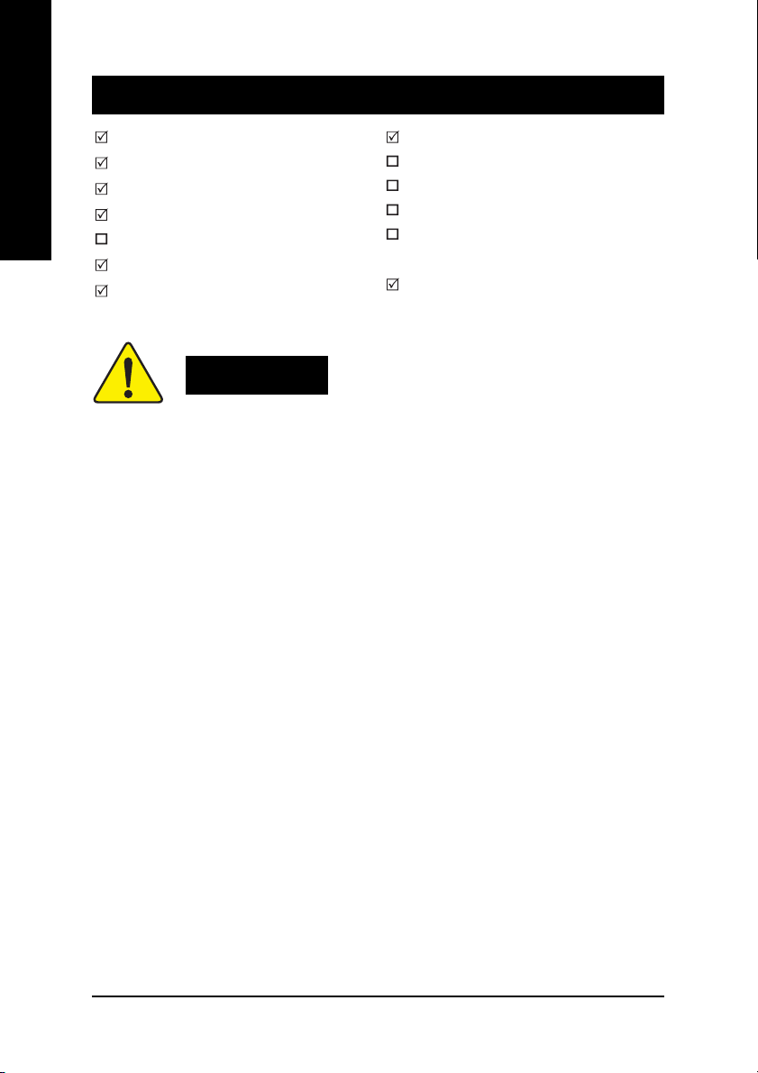
Item Checklist
English
Computer motherboards and expansion cards contain very delicate Integrated Circuit (IC) chips. To
protect them against damage from static electricity, you should follow some precautions whenever you
work on your computer.
The GA-8IE2004 Series motherboard
CD for motherboard driver & utility
GA-8IE2004 Series user's manual
Quick PC Installation Guide
RAID Manual
I/O Shield *
IDE cable x 2 / Floppy cable x 1
2 Port USB Cable x 1
4 Port USB Cable x 1
SPDIF KIT x 1 (SPD-KIT)
IEEE 1394 Cable x 1
Audio Combo Kit x 1
(SURROUND-Kit + SPDIF Out Kit)
Motherboard Settings Label
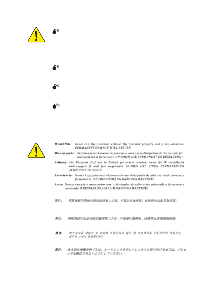
WARNING!
1. Unplug your computer when working on the inside.
2. Use a grounded wrist strap before handling computer components. If you do not have one, touch
both of your hands to a safely grounded object or to a metal object, such as the power supply
case.
3. Hold components by the edges and try not touch the IC chips, leads or connectors, or other
components.
4. Place components on a grounded antistatic pad or on the bag that came with the components
whenever the components are separated from the system.
5. Ensure that the ATX power supply is switched off before you plug in or remove the ATX power
connector on the motherboard.
Installing the motherboard to the chassis...
If the motherboard has mounting holes, but they don't line up with the holes on the base and there are
no slots to attach the spacers, do not become alarmed you can still attach the spacers to the mounting
holes. Just cut the bottom portion of the spacers (the spacer may be a little hard to cut off, so be careful of
your hands). In this way you can still attach the motherboard to the base without worrying about short
circuits. Sometimes you may need to use the plastic springs to isolate the screw from the motherboard
PCB surface, because the circuit wire may be near by the hole. Be careful, don't let the screw contact
any printed circuit write or parts on the PCB that are near the fixing hole, otherwise it may damage the
board or cause board malfunctioning.
* For GA-8IE2004-L only.
GA-8IE2004 Series Motherboard
- 4 -

Chapter 1 Introduction
Features Summary
Form Factor y 20cm x 29.4cm ATX size form factor, 4 layers PCB
®
CPU y Socket 478 for Intel
y Support Intel® Pentium® 4 (Northwood, 0.13 m) processor
y Support Intel® Pentium® 4 Processor with HT Technology
y Intel® Pentium® 4 533/400MHz FSB
y 2nd cache depends on CPU
Chipset y Chipset Intel® 845E HOST/AGP/Controller
y ICH2 I/O Controller Hub
Memory y 3 184-pin DDR DIMM sockets
y Supports PC2100 DDR or PC1600 DDR DIMM
y Supports up to 2GB DRAM (Max)
y Supports only 2.5V DDR DIMM
I/O Control y IT8712
Slots y 1 AGP slot 4X (1.5V) device support
y 5 PCI slots support 33MHz & PCI 2.2 compliant
On-Board IDE y 2 IDE bus master (DMA33/ATA66/ATA100) IDE ports for up to 4
ATAPI devices
y Supports PIO mode3, 4 (UDMA 33/ATA66/ATA100) IDE & ATAPI
CD-ROM
On-Board Peripherals y 1 Floppy port supports 2 FDD with 360K, 720K,1.2M, 1.44M
and 2.88M bytes
y 1 Parallel port supports Normal/EPP/ECP mode
y 2 Serial ports (COMA & COMB)
y 4 x USB 1.1 (2 Rear, 2 Front by cable)
y 1 Front Audio connector
Hardware Monitor y CPU/System fan revolution detect
y CPU temperature detect
y CPU warning temperature
y System voltage detect
y CPU/System fan fail warning
Micro FC-PGA2 Pentium® 4 processor
(Note)
English
- 5 -
to be continued......
Introduction

On-Board Sound y Realtek ALC655 CODEC
English
On-Board LAN * y Built-in RTL8100C *
PS/2 Connector y PS/2 Keyboard interface and PS/2 Mouse interface
BIOS y Licensed AWARD BIOS
Additional Features y PS/2 Keyboard password power on
Overclocking y Over Clock (CPU/DDR/AGP/PCI) by BIOS
y Supports Jack-Sensing function
y Line Out / 2 front speaker
y Line In / 2 rear speaker(by s/w switch)
y Mic In / center & subwoofer(by s/w switch)
y SPDIF In / Out
y CD In / AUX In / Game port
y 1 RJ45 port *
y Supports Q-Flash
y PS/2 Mouse power on
y External Modem wake up
y STR(Suspend-To-RAM)
y AC Recovery
y USB KB/Mouse wake up from S3
y Poly fuse for keyboard over-current protection
y Supports @BIOS
y Supports EasyTune 4
y Over voltage (CPU/DDR/AGP) by BIOS
HT functionality requirement content :
Enabling the functionality of Hyper-Threading Technology for your computer system requires all
of the following platform components:
- CPU: An Intel
- Chipset: An Intel
- BIOS: A BIOS that supports HT Technology and has it enabled
- OS: An operation system that has optimizations for HT Technology
Please set the CPU host frequency in accordance with your processor's specifications.
We don't recommend you to set the system bus frequency over the CPU's specification because
these specific bus frequencies are not the standard specifications for CPU, chipset and most of the
peripherals. Whether your system can run under these specific bus frequencies properly will
depend on your hardware configurations, including CPU, Chipsets, SDRAM, Cards…etc.
®
Pentium 4 Processor with HT Technology
®
Chipset that supports HT Technology
* For GA-8IE2004-L only.
GA-8IE2004 Series Motherboard
- 6 -
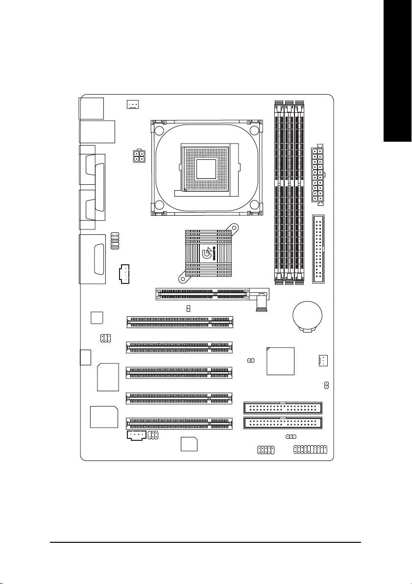
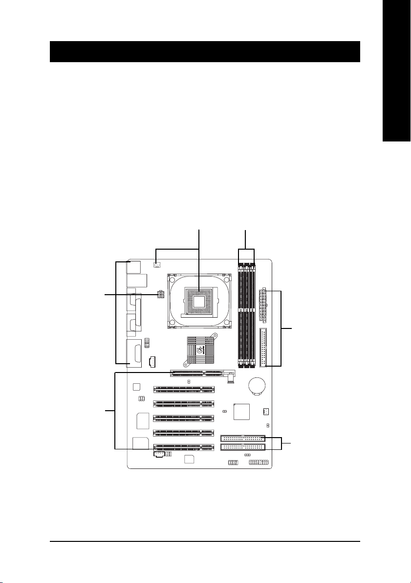
GA-8IE2004 Series Motherboard Layout
English
KB_MS
LINE_OUTMIC_IN
CODEC
(-L)*
USB
LAN*
COMA
LPTGAME
COMB
LINE_IN
SUR_CEN
RTL*
8100C
ITE8712
F_AUDIO
CD_IN
CPU_FAN
ATX_12V
Intel 845E
AGP
2X_DET
Hyper Threading
SPDIF_IO
AUX_IN
SOCKET478
P4 Titan
BIOS
PCI1
PCI2
PCI3
PCI4
PCI5
CLR_PWD
F_USB
GA-8IE2004
DDR1
ICH2
PWR_LED
DDR2
BATTERY
ATX
FDD
DDR3
SYS _FAN
CI
IDE2
IDE1
F_PANEL
* For GA-8IE2004-L only.
- 7 -
Hardware Installation Process
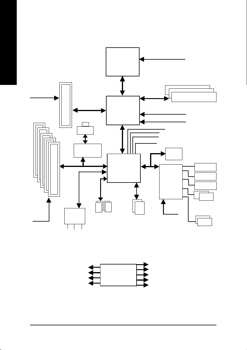
Block Diagram
English
PCICLK
(33MHz)
AGPCLK
(66MHz)
5 PCI
AGP 4X
CODEC
RTL8100C*
AC97
MIC
LINE-IN
RJ45*
AC97 Link
LINE-OUT
4 USB
Ports
Pentium 4
CPU
400/533 MHz
Intel
845E
Intel
ICH 2
CPUCLK+/- (100/133 MHz)
System Bus
100/133MHz
48 MHz
LPC BUS
ATA33/66/100
IDE Channels
HCLK+/- (100/133MHz)
MCHCLK(66MHz)
66 MHz
33 MHz
14.318 MHz
BIOS
ITE
8712
48 MHz
DDR
Game Port
Floppy
LPT Port
PS/2
KB/Mouse
COM
Ports
PCICLK (33MHz)
USBCLK (48MHz)
14.318 MHz
33 MHz
* For GA-8IE2004-L only.
GA-8IE2004 Series Motherboard
CLKGEN
- 8 -
MCH66 (66MHz)
CPUCLK+/- (100/133MHz)
AGPCLK (66MHz)
MCHCLK+/- (100/133MHz)
ICH3V66 (66MHz)

English
- 9 -
Introduction

English
GA-8IE2004 Series Motherboard
- 10 -
Chapter 2 Hardware Installation Process
To set up your computer, you must complete the following steps:
Step 1- Install the Central Processing Unit (CPU)
Step 2- Install memory modules
Step 3- Install expansion cards
Step 4- Connect ribbon cables, cabinet wires, and power supply
Step 5- Setup BIOS software
Step 6- Install supporting software tools
English
Step 4
Step 3
Step 1
Step 2
Step 4
Step 4
- 11 -
Hardware Installation Process
Step 1: Install the Central Processing Unit (CPU)
English
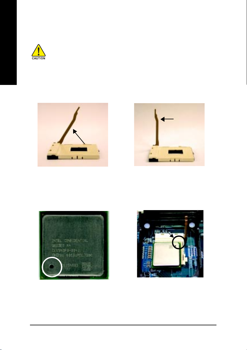
Step 1-1: CPU Installation
Before installing the processor, adhere to the following warning:
1. Please make sure the CPU type is supported by the motherboard.
2. If you do not match the CPU socket Pin 1 and CPU cut edge well, it will
cause improper installation. Please change the insert orientation.
Angling the
rod to 65
1. Angling the rod to 65-degree maybe feel a
kind of tight , and then continue pull the rod to
90-degree when a noise "cough" made.
0
Pin1 indicator
3. CPU Top View
Socket
Actuation
Lever
2. Pull the rod to the 90-degree directly .
Pin1 indicator
4. Locate Pin 1 in the socket and look
for a (golden) cut edge on the CPU
upper corner. Then insert the CPU
into the socket.
GA-8IE2004 Series Motherboard
- 12 -
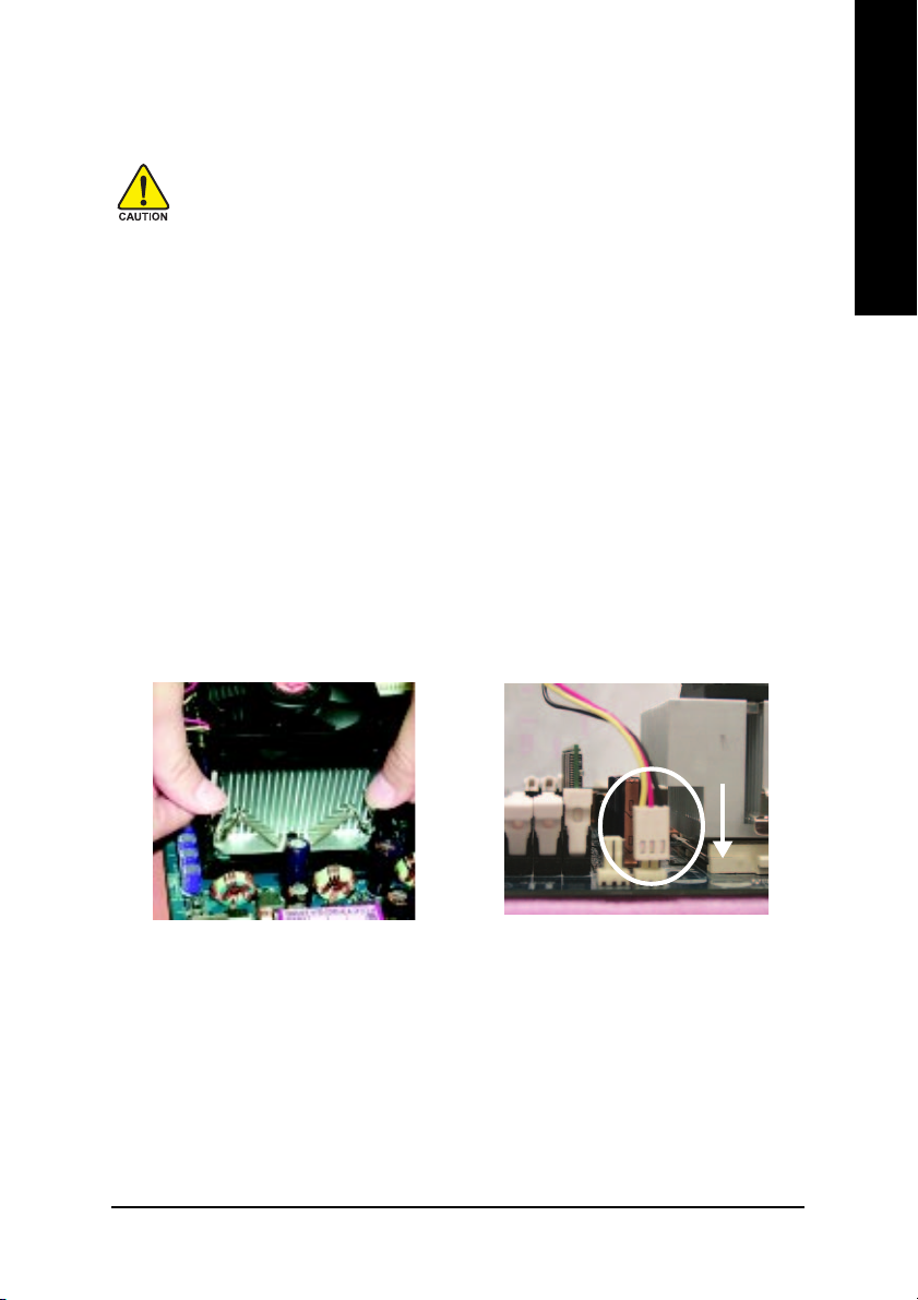
Step 1-2: CPU Heat Sink Installation
Before installing the CPU cooling fan, adhere to the following warning:
1. Please use Intel approved cooling fan.
2. We recommend you to apply the thermal tape to provide better heat
conduction between your CPU and cooling fan.
(The CPU cooling fan might stick to the CPU due to the hardening of
the thermal paste. During this condition if you try to remove the cool-
ing fan, you might pull the processor out of the CPU socket alone with
the cooling fan, and might damage the processor. To avoid this from
happening, we suggest you to either use thermal tape instead of
thermal paste, or remove the cooling fan with extreme caution.)
3.Make sure the CPU fan power cable is plugged in to the CPU fan
connector, this completes the installation.
Please refer to CPU cooling fan user's manual for more detail
installation procedure.
English
1. Fasten the cooling fan supporting-
base onto the CPU socket on the
motherboard.
- 13 -
2. Make sure the CPU fan is plugged
to the CPU fan connector, than
install complete.
Hardware Installation Process
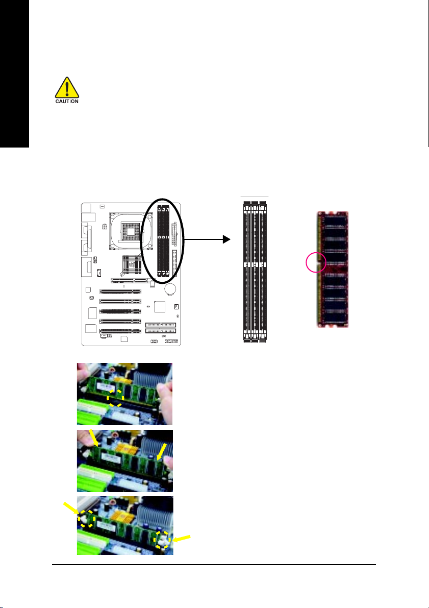
Step 2: Install Memory Modules
English
The motherboard has 3 dual inline memory module (DIMM) sockets. The BIOS will automatically
detects memory type and size. To install the memory module, just push it vertically into the DIMM
socket. The DIMM module can only fit in one direction due to the notch. Memory size can vary
between sockets.
Before installing the memory modules, adhere to the following warning:
1. When DIMM LED is ON, do not install / remove DIMM from socket.
2. Please note that the DIMM module can only fit in one direction due to
the one notch. Wrong orientation will cause improper installation.
Please change the insert orientation.
Notch
DDR
GA-8IE2004 Series Motherboard
1. The DIMM socket has a notch, so the DIMM memory
module can only fit in one direction.
2. Insert the DIMM memory module vertically into the DIMM
socket. Then push it down.
3. Close the plastic clip at both edges of the DIMM sockets to
lock the DIMM module.
Reverse the installation steps when you wish to remove
the DIMM module.
- 14 -
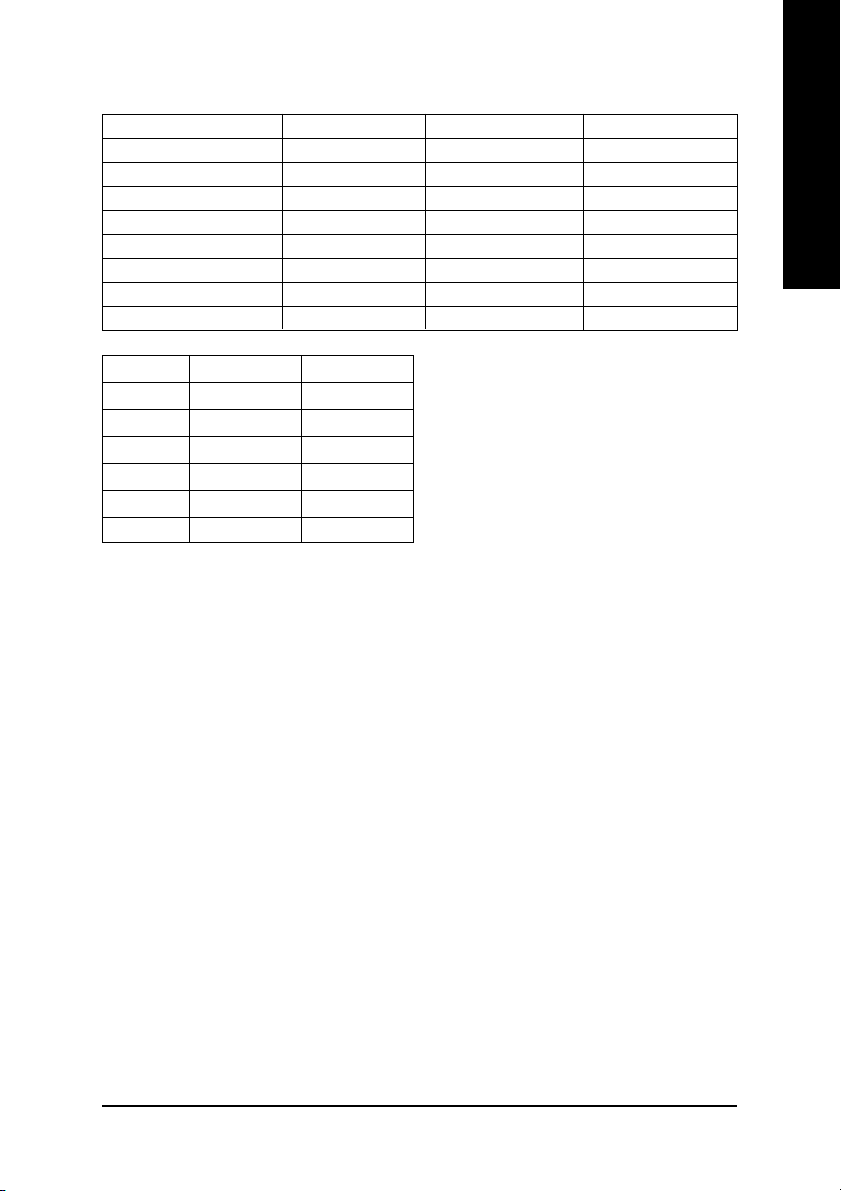
Total Memory Sizes With Unbuffered DDR DIMM
Devices used on DIMM 1 DIMM x 64 / x 72 2 DIMMs x 64 / x 72 3 DIMMs x 64 / x 72
64 Mbit (2Mx8x4 banks) 128 MBytes 256 MBytes 256 MBytes
64 Mbit (1Mx16x4 banks) 32 MBytes 64 MBytes 96 MBytes
128 Mbit(4Mx8x4 banks) 256 MBytes 512 MBytes 512 MBytes
128 Mbit(2Mx16x4 banks) 64 MBytes 128 MBytes 192 MBytes
256 Mbit(8Mx8x4 banks) 512 MBytes 1 GBytes 1 GBytes
256 Mbit(4Mx16x4 banks) 128 MBytes 256 MBytes 384 MBytes
512 Mbit(16Mx8x4 banks) 1 GBytes 2 GBytes 2 GBytes
512 Mbit(8Mx16x4 banks) 256 MBytes 512 MBytes 768 MBytes
DDR1 DDR2 DDR3
SS S
DS S
DD X
DX D
SD X
SX D
D: Double Sided DIMM S:Single Sided DIMM
X: Not Use
English
DDR Introduction
Established on the existing SDRAM infrastructure, DDR (Double Data Rate) memory is a high
performance and cost-effective solution that allows easy adoption for memory vendors, OEMs, and
system integrators.
DDR memory is a great evolutionary solution for the PC industry that builds on the existing
SDRAM architecture, yet make the awesome advances in solving the system performance bottleneck
by doubling the memory bandwidth. Nowadays, with the highest bandwidth of 3.2GB/s of DDR400
memory and complete line of DDR400/333/266/200 memory solutions, DDR memory is the best
choice for building high performance and low latency DRAM subsystem that are suitable for servers,
workstations, and full range of desktop PCs.
- 15 -
Hardware Installation Process
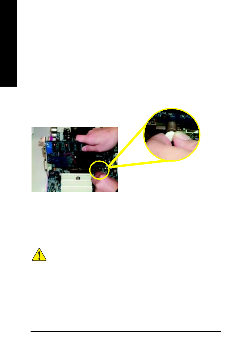
Step 3: Install expansion cards
1. Read the related expansion card's instruction document before install the expansion card into the
English
2. Remove your computer's chassis cover, screws and slot bracket from the computer.
3. Press the expansion card firmly into expansion slot in motherboard.
4. Be sure the metal contacts on the card are indeed seated in the slot.
5. Replace the screw to secure the slot bracket of the expansion card.
6. Replace your computer's chassis cover.
7. Power on the computer, if necessary, setup BIOS utility of expansion card from BIOS.
8. Install related driver from the operating system.
computer.
AGP Card
Please carefully pull out the small white-drawable
bar at the end of the AGP slot when you try to
install / uninstall the AGP card. Please align the
AGP card to the onboard AGP slot and press
firmly down on the slot. Make sure your AGP
card is locked by the small white-drawable bar.
When an AGP 2X (3.3V) card is installed the 2X_DET will light up, indicating a non-supported
graphics card is inserted. Informing users that system might not boot up normally due to
AGP 2X (3.3V) is not supported by the chipset.
GA-8IE2004 Series Motherboard
- 16 -
Step 4: Connect ribbon cables, cabinet wires and
power supply
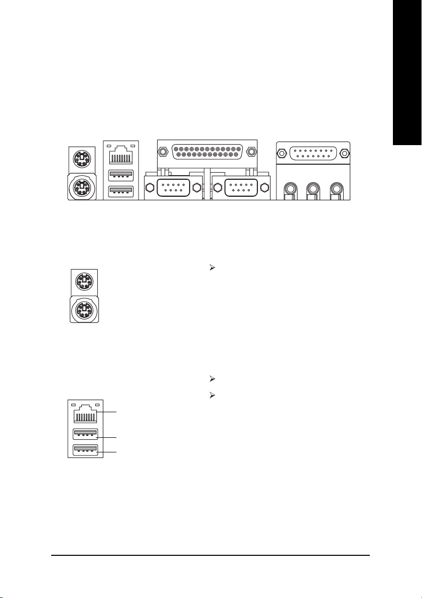
Step 4-1: I/O Back Panel Introduction
English
X
XX
X PS/2 Keyboard and PS/2 Mouse Connector
XX
Y
PS/2 Mouse Connector
(6 pin Female)
PS/2 Keyboard Connector
(6 pin Female)
Y LAN* / USB Connector
LAN*
USB 0
USB 1
Z
This connector supports standard PS/2
keyboard and PS/2 mouse.
LAN is fast Ethernet with 10/100Mbps speed.*
Before you connect your device(s) into USB
connector(s), please make sure your device(s)
such as USB keyboard,mouse, scanner, zip,
speaker...etc. Have a standard USB interface.
Also make sure your OS supports USB
controller. If your OS does not support USB
controller, please contact OS vendor for
possible patch or driver upgrade. For more
information please contact your OS or device(s)
vendors.
[
\
* For GA-8IE2004-L only.
- 17 -
Hardware Installation Process
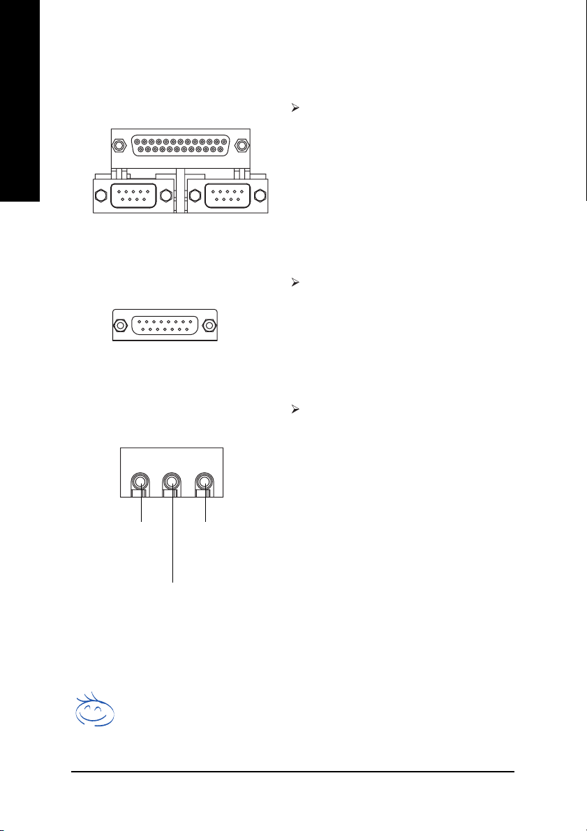
Z Parallel Port and Serial Ports (COMA / COMB)
English
[ Game / MIDI Ports
\ Audio Connectors
Parallel Port
(25 pin Female)
COMA COMB
Serial Port (9 pin Male)
Joystick/ MIDI (15 pin Female)
Line Out
(Front Speaker)
(Rear Speaker)
MIC In
(Center and
Subwoofer)
Line In
This connector supports 2 standard COM ports
and 1 Parallel port. Device like printer can be
connected to Parallel port; mouse and modem
etc. can be connected to Serial ports.
This connector supports joystick, MIDI
keyboard and other relate audio devices.
After install onboard audio driver, you may connect speaker to Line Out jack, microphone to MIC
In jack. Device like CD-ROM,walkman etc. can
be connected to Line-In jack.
Please note:
You are able to use 2-/4-/6-channel audio feature
by S/W selection.
If you want to enable 6-channel function, you
have 2 choose for hardware connection.
Method1:
Connect "Front Speaker" to "Line Out"
Connect "Rear Speaker" to "Line In"
Connect "Center and Subwoofer" to "MIC Out ".
Method2:
You can refer to page 25, and contact your
nearest dealer for optional SUR_CEN cable.
If you want the detail information for 2-/4-/6-channel audio setup
installation, please refer to page 65.
GA-8IE2004 Series Motherboard
- 18 -
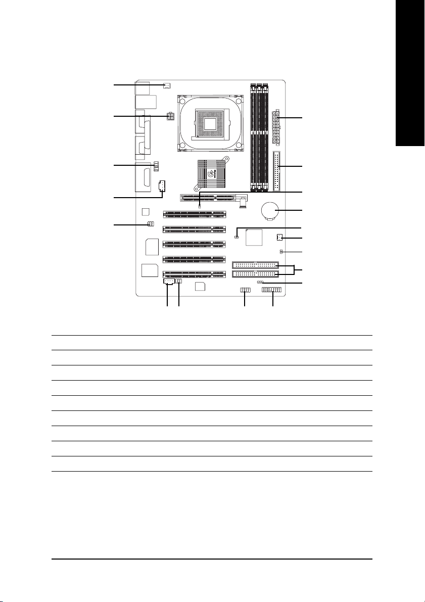
Step 4-2: Connectors Introduction
3
English
10
12
11
1) ATX_12V
2) ATX
3) CPU_FAN
4) SYS_FAN
5) FDD
6) IDE1 / IDE2
7) F_PANEL
8) PWR_LED
9) 2X_DET
1
13
14
715
2
5
9
18
17
4
16
6
8
10) F_AUDIO
11) SUR_CEN
12) CD_IN
13) AUX_IN
14) SPDIF_IO
15) F_USB
16) C I
17) CLR_PWD
18) BATTERY
- 19 -
Hardware Installation Process
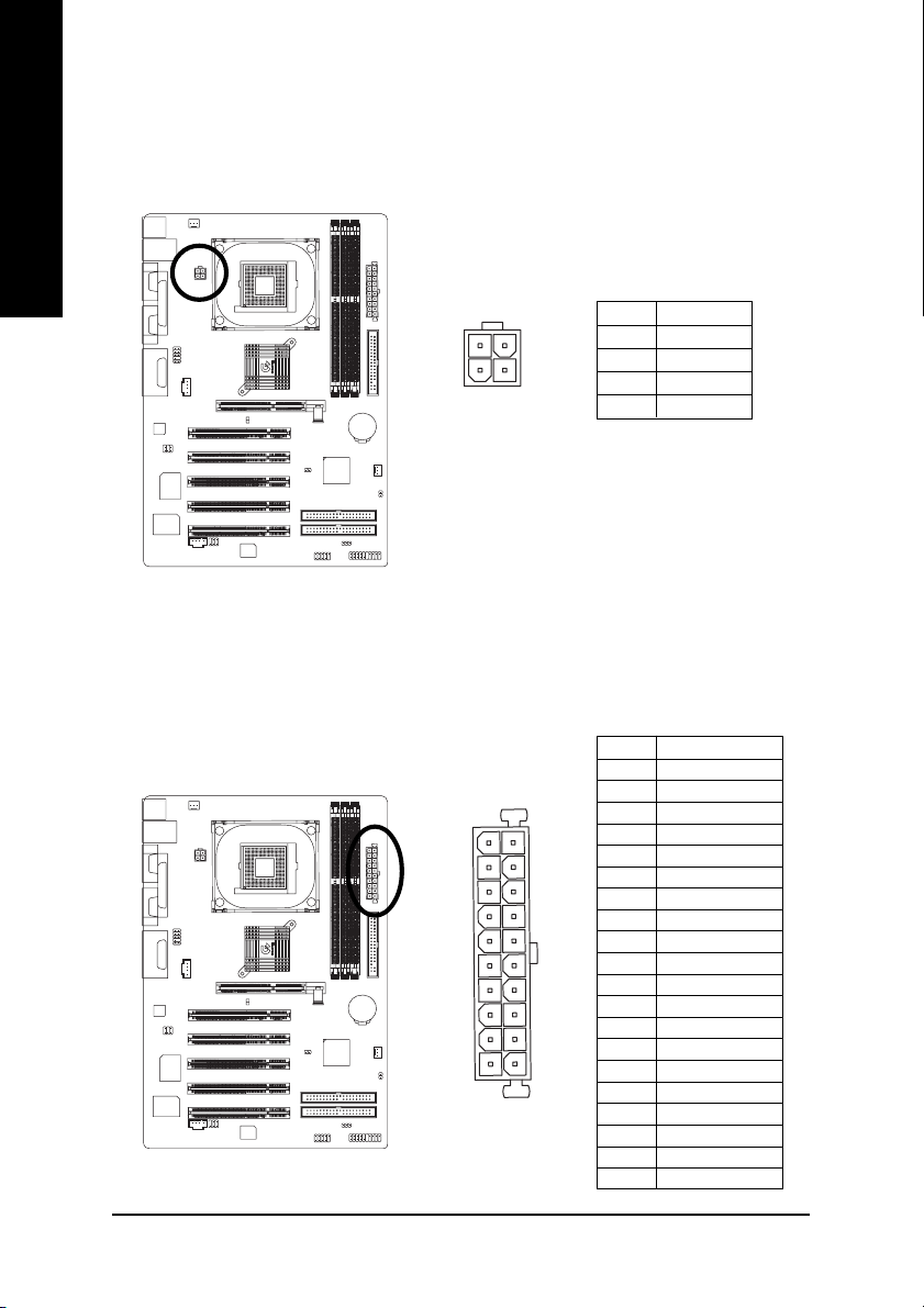
1) ATX_12V (+12V Power Connector)
English
2) ATX (ATX Power)
This connector (ATX_12V) supplies the CPU operation voltage (Vcore).
If this "ATX_12V connector" is not connected, system cannot boot.
Pin No. Definition
3
1
4
2
1 GND
2 GND
3 +12V
4 +12V
AC power cord should only be connected to your power supply unit after ATX power cable and
other related devices are firmly connected to the mainboard.
10
1
20
11
Pin No. Definition
1 3.3V
2 3.3V
3 GND
4 VCC
5 GND
6 VCC
7 GND
8 Power Good
9 5V SB (stand by +5V)
10 +12V
11 3.3V
12 -12V
13 GND
14 PS_ON(soft on/off)
15 GND
16 GND
17 GND
18 -5V
19 VCC
20 VCC
GA-8IE2004 Series Motherboard
- 20 -
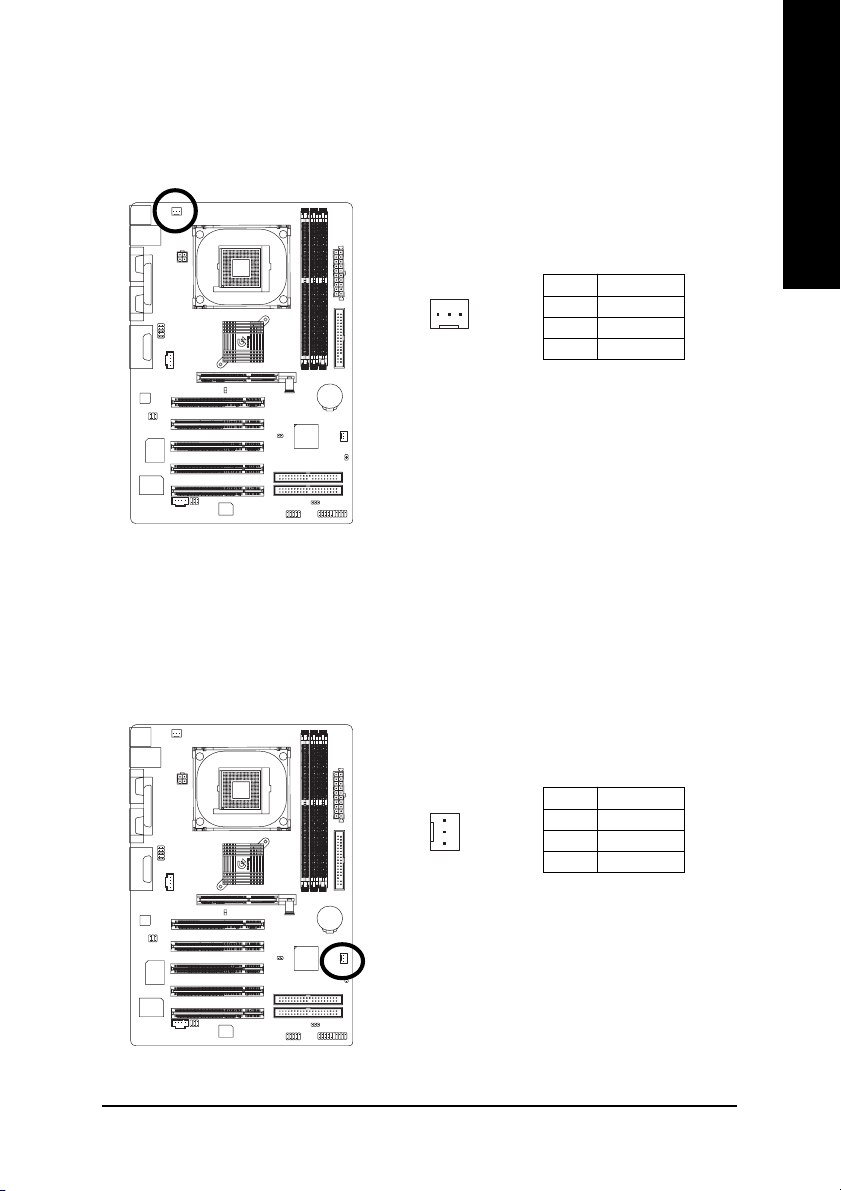
3) CPU_FAN (CPU Fan Connector)
Please note, a proper installation of the CPU cooler is essential to prevent the CPU from running
under abnormal condition or damaged by overheating. The CPU fan connector supports Max.
current up to 600 mA.
Pin No. Definition
1
1 GND
2 +12V
3 Sense
4) SYS_FAN (System Fan Connector)
This connector allows you to link with the cooling fan on the system case to lower the system
temperature.
English
- 21 -
1
Pin No. Definition
1 GND
2 +12V
3 Sense
Hardware Installation Process
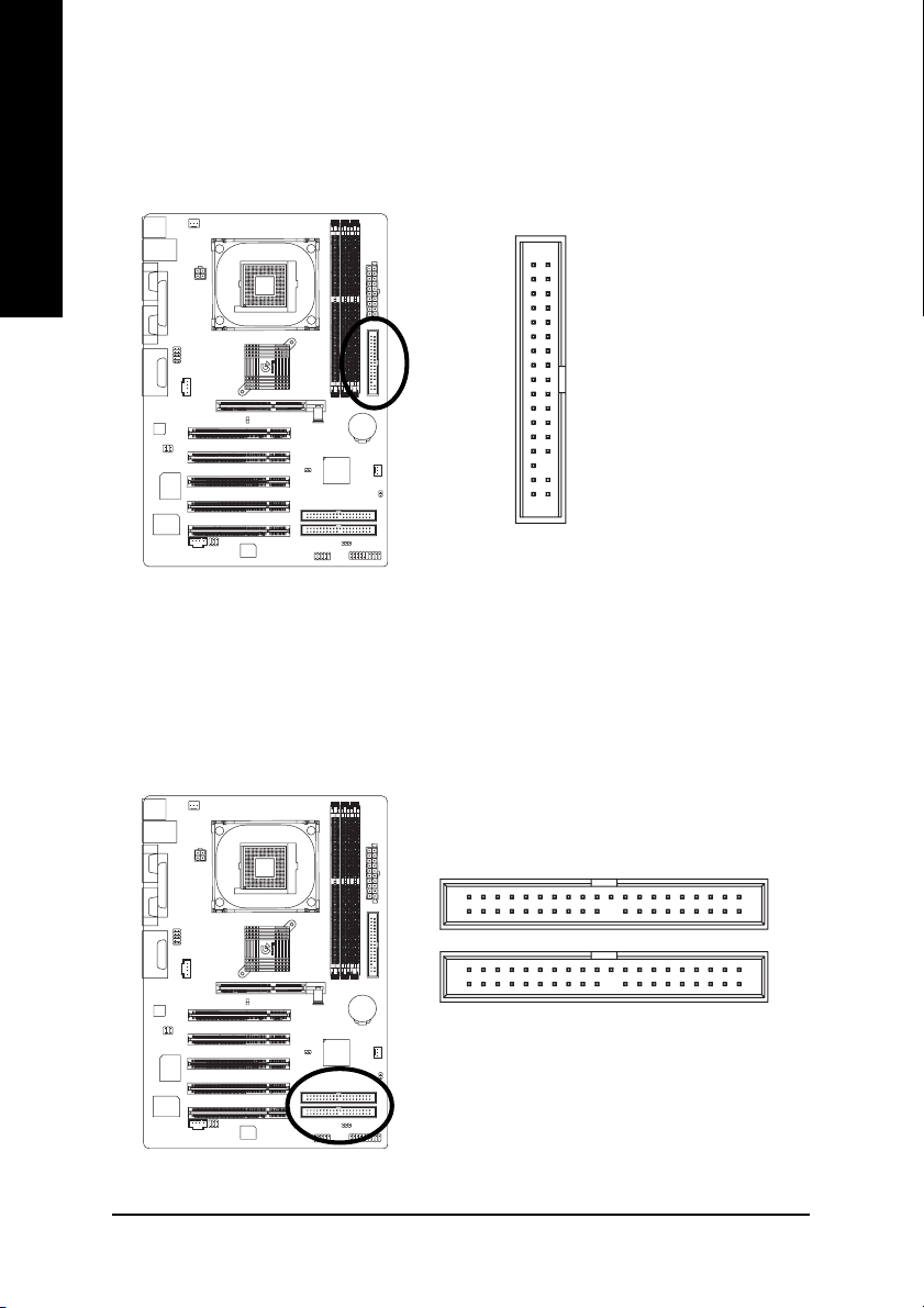
5) FDD (Floppy Connector)
English
Please connect the floppy drive ribbon cables to FDD. It supports 360K, 1.2M, 720K, 1.44M and
2.88M bytes floppy disk types.
The red stripe of the ribbon cable must be the same side with the Pin1.
34
2
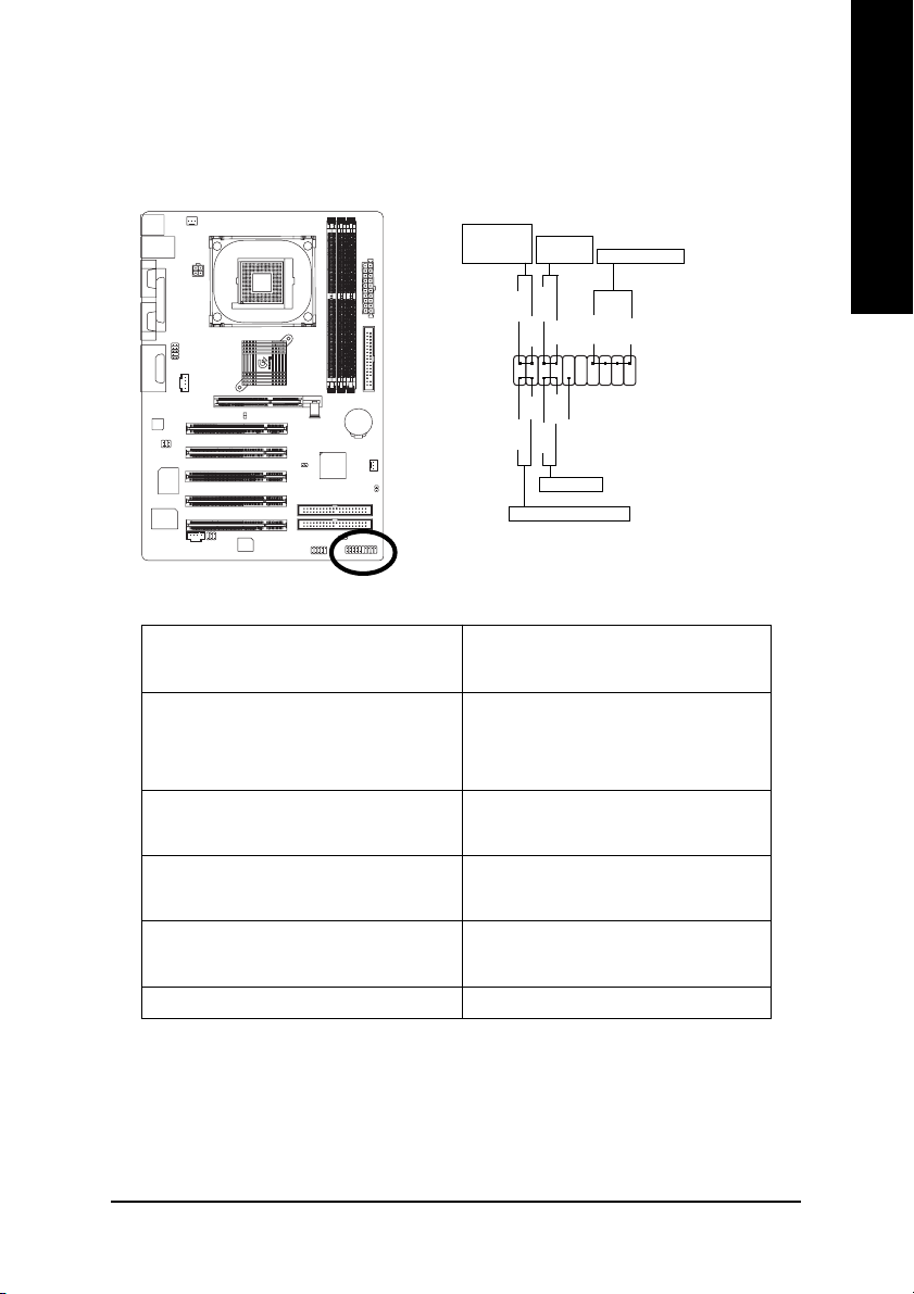
6) IDE1 / IDE2 (IDE1 / IDE2 Connector)
Important Notice:
Please connect first hard disk to IDE1 and connect CD-ROM to IDE2.
The red stripe of the ribbon cable must be the same side with the Pin1.
33
1
139
GA-8IE2004 Series Motherboard
IDE2
IDE1
240
- 22 -
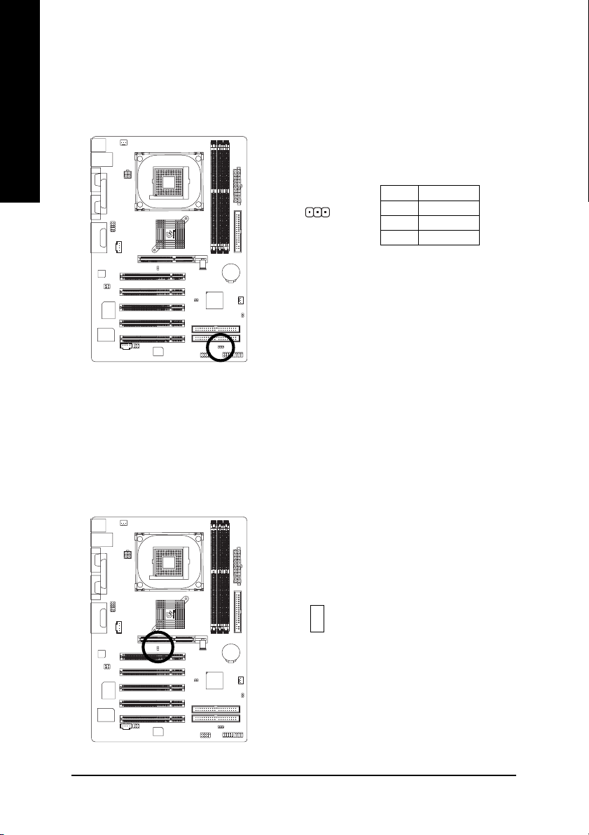
7) F_PANEL (2 x 10 pins Connector)
Please connect the power LED, PC speaker, reset switch and power switch etc of your chassisfront
panel to the F_PANEL connector according to the pin assignment above.
Message LED/
Power/
Sleep LED
HD (IDE Hard Disk Active LED) Pin 1: LED anode(+)
(Blue) Pin 2: LED cathode(-)
SPK (Speaker Connector) Pin 1: VCC(+)
(Amber) Pin 2- Pin 3: NC
RST (Reset Switch) Open: Normal Operation
(Green) Close: Reset Hardware System
PW (Soft Power Connector) Open: Normal Operation
(Red) Close: Power On/Off
MPD (Message LED/ Power/ Sleep LED) Pin 1: LED anode(+)
(Yellow) Pin 2: LED cathode(-)
NC (Purple) N C
Soft Power
Connector
PW+
MPD+
PW-
MPD-
11
2
1
1
1
HD-
RST+
HD+
RST-
Reset Switch
IDE Hard Disk Active LED
Pin 4: Data(-)
Speaker Connector
SPK+
1
NC
SPK-
20
19
English
- 23 -
Hardware Installation Process
8) PWR_LED
English
9) 2X_DET
PWR_LED is connect with the system power indicator to indicate whether the system is on/off.
It will blink when the system enters suspend mode. If you use dual color LED, power LED will turn
to another color.
Pin No. Definition
1
When an AGP 2X (3.3V) card is installed the AGP_LED will light up, indicating a non-supported
graphics card is inserted. Informing users that system might not boot up normally due to AGP 2X
(3.3V) is not supported by the chipset.
1 MPD+
2 MPD-
3 MPD-
GA-8IE2004 Series Motherboard
+
_
- 24 -
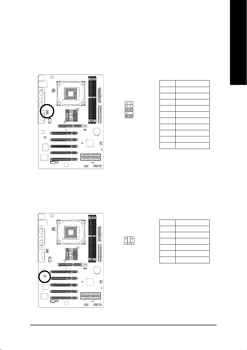
10) F_AUDIO (Front Audio Connector)
If you want to use Front Audio connector, you must remove 5-6, 9-10 Jumper.
In order to utilize the front audio header, your chassis must have front audio connector. Also please
make sure the pin assigment on the cable is the same as the pin assigment on the MB header. To
find out if the chassis you are buying support front audio connector, please contact your dealer.
Please note, you can have the of using front audio connector or of using rear audio connector to
play sound.
Pin No. Definition
1 MIC
2 GND
2
1
9
10
3 REF
4 Power
5 Front Audio (R)
6 Rear Audio (R)
7 Reserved
8 No Pin
9 Front Audio (L)
10 Rear Audio (L)
11) SUR_CEN (Surround Center Connector)
Please contact your nearest dealer for optional SUR_CEN cable.
English
2
1
- 25 -
Pin No. Definition
1 SUR OUTL
6
5
2 SUR OUTR
3 GND
4 No Pin
5 CENTER_OUT
6 BASS_OUT
Hardware Installation Process
 Loading...