

Gigabyte GA-8I945G PRO, GA-8I945G User Manual
GA-8I945G Pro/
GA-8I945G
Intel® Pentium® D / Pentium® 4 LGA775 Processor Motherboard
User's Manual
Rev. 1005
12ME-8I945GP-1005
* The WEEE marking on the product indicates this product must not be disposed of with user's other household waste
and must be handed over to a designated collection point for the recycling of waste electrical and electronic equipment!!
* The WEEE marking applies only in European Union's member states.
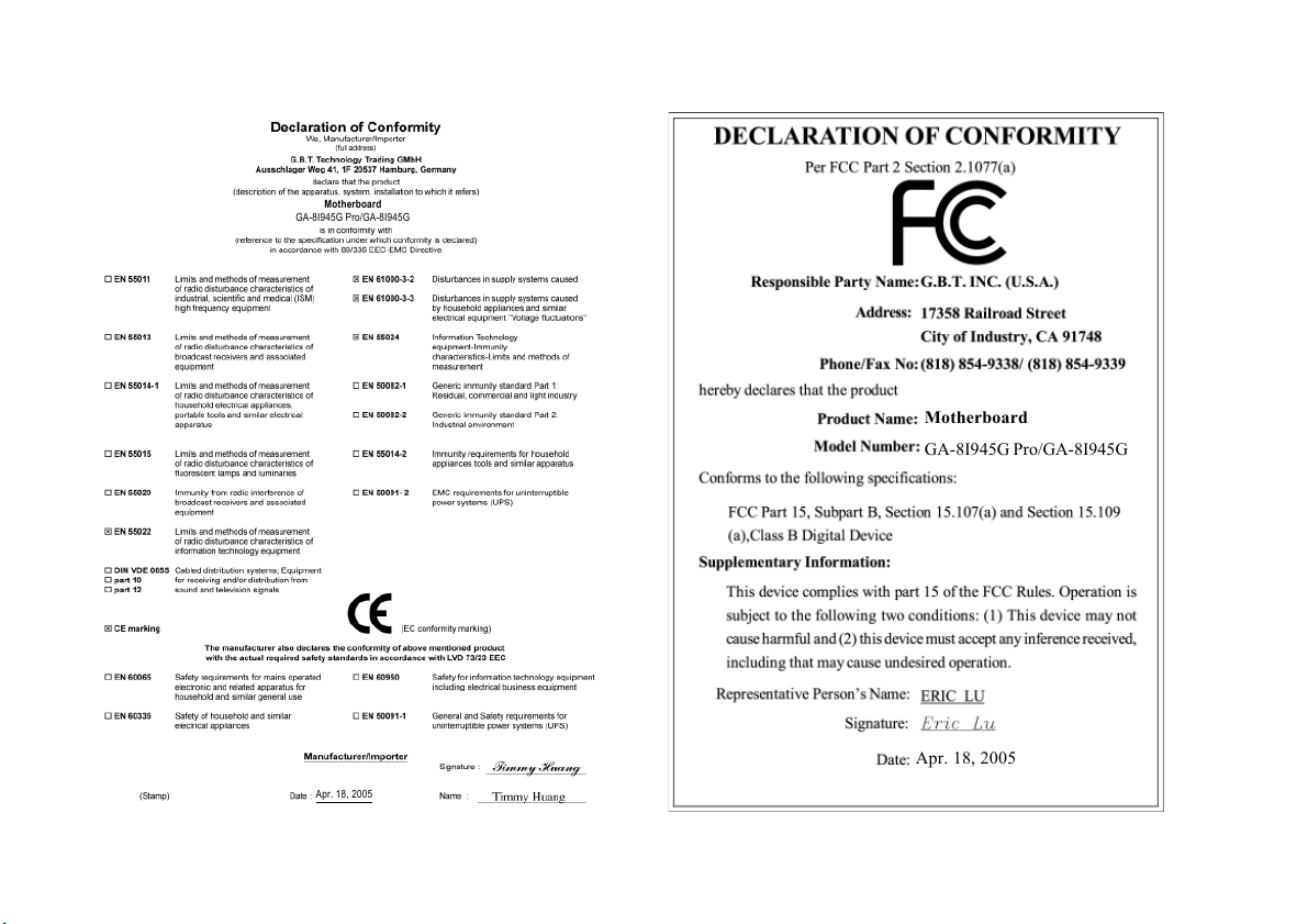
Motherboard
GA-8I945G Pro/GA-8I945G
Apr. 18, 2005
Motherboard
GA-8I945G Pro/GA-8I945G
Apr. 18, 2005
Copyright
© 2005 GIGA-BYTE TECHNOLOGY CO., LTD. All rights reserved.
The trademarks mentioned in the manual are legally registered to their respective companies.
Notice
The written content provided with this product is the property of Gigabyte.
No part of this manual may be reproduced, copied, translated, or transmitted in any form or by any
means without Gigabyte's prior written permission. Specifications and features are subject to
change without prior notice.
Product Manual Classification
In order to assist in the use of this product, Gigabyte has categorized the user manual in the
following:
For quick installation, please refer to the "Hardware Installation Guide" included with the
product.
For detailed product information and specifications, please carefully read the
"Product User Manual".
For detailed information related to Gigabyte's unique features, please go to "Technology
Guide" section on Gigabyte's website to read or download the information you need.
For more product details, please click onto Gigabyte's website at www.gigabyte.com.tw
Item Checklist
IDE Cable x 2 & FDD Cable x 1
Serial ATAII Cable x 2
Serial ATA Power Cable x 2
2 Ports USB 2.0 + 2 Ports 1394 Cable x 1
I/O Shield
* The items listed above are for reference only, and are subject to change without notice.
Optional Accessories
8-Channel Audio Combo kit (Part Number: 12CR1-1SPAUD-21/R)
Table of Contents
GA-8I945G Pro Motherboard Layout ............................................................................. 6
GA-8I945G Motherboard Layout.................................................................................... 7
Block Diagram ................................................................................................................ 8
Chapter 1 Hardware Installation ..................................................................................... 9
1-1 Considerations Prior to Installation .................................................................... 9
1-2 Feature Summary .......................................................................................... 10
1-3 Installation of the CPU and Heatsink .............................................................. 12
1-3-1 Installation of the CPU ......................................................................................... 12
1-3-2 Installation of the Heatsink .................................................................................. 13
1-4 Installing/Removing Cool-Plus (Northbridge Cooling Fan)
1-5 Installation of Memory .................................................................................... 14
1-6 Installation of Expansion Cards ...................................................................... 16
1-7 I/O Back Panel Introduction ........................................................................... 17
1-8 Connectors Introduction .................................................................................. 18
Chapter 2 BIOS Setup ................................................................................................ 29
The Main Menu (For example: BIOS Ver. : GA-8I945G Pro F2d) ............................ 30
2-1 Standard CMOS Features ............................................................................. 32
2-2 Advanced BIOS Features .............................................................................. 34
2-3 Integrated Peripherals ..................................................................................... 36
2-4 Power Management Setup ............................................................................. 39
2-5 PnP/PCI Configurations ................................................................................. 41
2-6 PC Health Status ........................................................................................... 42
2-7 MB Intelligent Tweaker(M.I.T.) ....................................................................... 44
2-8 Select Language
2-9 Load Fail-Safe Defaults ................................................................................... 47
2-10 Load Optimized Defaults ................................................................................. 48
2-11 Set Supervisor/User Password ..................................................................... 48
2-12 Save & Exit Setup ......................................................................................... 49
2-13 Exit Without Saving ....................................................................................... 49
....................................................................................... 47
......................... 14
Only for GA-8I945G Pro.
- 4 -
Chapter 3 Install Drivers ............................................................................................. 51
3-1 Install Chipset Drivers .................................................................................... 51
3-2 Software Applications ..................................................................................... 52
3-3 Driver CD Information .................................................................................... 52
3-4 Hardware Information ..................................................................................... 53
3-5 Contact Us ..................................................................................................... 53
Chapter 4 Appendix ................................................................................................... 55
4-1 Unique Software Utilities ................................................................................ 55
4-1-1 EasyTune 5 Introduction ..................................................................................... 56
4-1-2 Xpress Recovery2 Introduction ......................................................................... 57
4-1-3 Flash BIOS Method Introduction ........................................................................ 59
4-1-4 Serial ATA BIOS Setting Utility Introduction
4-1-5 2- / 4- / 6- / 8- Channel Audio Function Introduction ...................................... 77
4-2 Troubleshooting ............................................................................................... 81
................................................. 70
Only for GA-8I945G Pro.
- 5 -
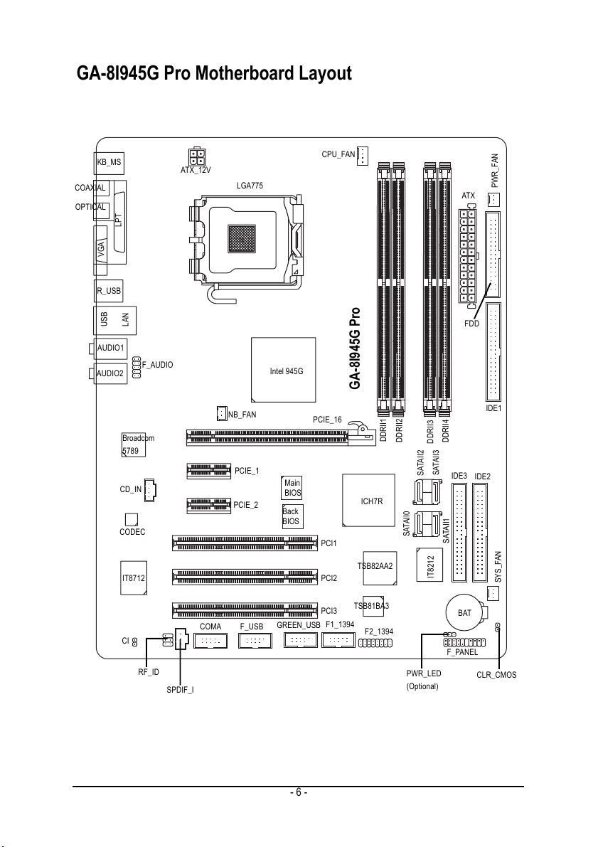
GA-8I945G Pro Motherboard Layout
COAXIAL
OPTICAL
KB_MS
VGA
R_USB
USB
AUDIO1
AUDIO2
LPT
LAN
Broadcom
5789
CD_IN
CODEC
IT8712
F_AUDIO
ATX_12V
LGA775
NB_FAN
PCIE_1
PCIE_2
Intel 945G
Main
BIOS
Back
BIOS
CPU_FAN
PCIE_16
PCI1
PCI2
GA-8I945G Pro
DDRII1
DDRII2
SATAII2
ICH7R
SATAII0
TSB82AA2
DDRII3
SATAII3
IT8212
DDRII4
IDE3
SATAII1
ATX
PWR_FAN
FDD
IDE1
IDE2
SYS_FAN
TSB81BA3
PCI3
GREEN_USB
F_USB
COMA
CI
RF_ID
SPDIF_I
F1_1394
F2_1394
PWR_LED
(Optional)
BAT
F_PANEL
CLR_CMOS
- 6 -
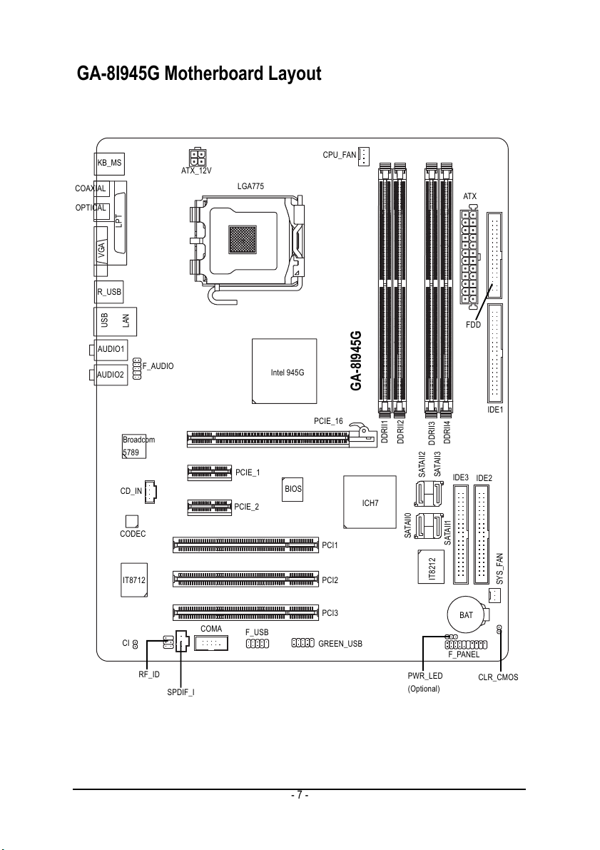
GA-8I945G Motherboard Layout
COAXIAL
OPTICAL
KB_MS
VGA
R_USB
USB
AUDIO1
AUDIO2
LPT
LAN
Broadcom
5789
CD_IN
CODEC
F_AUDIO
ATX_12V
LGA775
PCIE_1
PCIE_2
Intel 945G
BIOS
CPU_FAN
PCIE_16
PCI1
GA-8I945G
DDRII1
DDRII2
ICH7
SATAII0
SATAII2
DDRII3
SATAII3
DDRII4
IDE3
SATAII1
ATX
FDD
IDE1
IDE2
IT8712
CI
RF_ID
SPDIF_I
COMA
F_USB
- 7 -
PCI2
PCI3
GREEN_USB
PWR_LED
(Optional)
IT8212
SYS_FAN
BAT
F_PANEL
CLR_CMOS
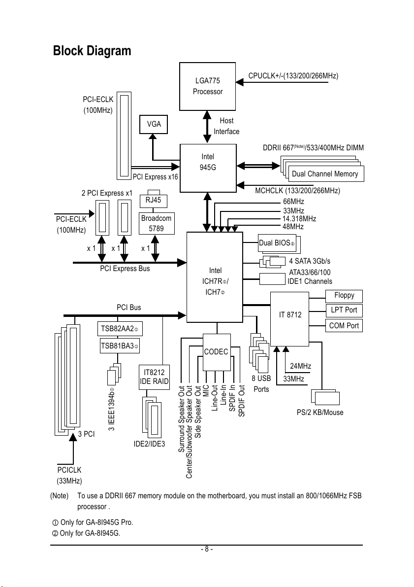
Block Diagram
PCI-ECLK
(100MHz)
3 PCI
PCI-ECLK
(100MHz)
2 PCI Express x1
x 1
x 1
PCI Express Bus
PCI Bus
TSB82AA2
TSB81BA3
3 IEEE1394b
VGA
PCI Express x16
RJ45
Broadcom
5789
x 1
IT8212
IDE RAID
IDE2/IDE3
LGA775
Processor
Host
Interface
Intel
945G
Intel
/
ICH7R
ICH7
CODEC
MIC
Line-In
Line-Out
SPDIF In
Side Speaker Out
Surround Speaker Out
CPUCLK+/-(133/200/266MHz)
DDRII 667
MCHCLK (133/200/266MHz)
Dual BIOS
8 USB
Ports
SPDIF Out
(Note)
/533/400MHz DIMM
Dual Channel Memory
66MHz
33MHz
14.318MHz
48MHz
4 SATA 3Gb/s
ATA33/66/100
IDE1 Channels
IT 8712
24MHz
33MHz
PS/2 KB/Mouse
Floppy
LPT Port
COM Port
PCICLK
(33MHz)
(Note) To use a DDRII 667 memory module on the motherboard, you must install an 800/1066MHz FSB
processor .
Only for GA-8I945G Pro.
Only for GA-8I945G.
Center/Subwoofer Speaker Out
- 8 -
Chapter 1 Hardware Installation
1-1 Considerations Prior to Installation
Preparing Your Computer
The motherboard contains numerous delicate electronic circuits and components which can
become damaged as a result of electrostatic discharge (ESD). Thus, prior to installation, please
follow the instructions below:
1. Please turn off the computer and unplug its power cord.
2. When handling the motherboard, avoid touching any metal leads or connectors.
3. It is best to wear an electrostatic discharge (ESD) cuff when handling electronic components
(CPU, RAM).
4. Prior to installing the electronic components, please have these items on top of an antistatic pad or
within a electrostatic shielding container.
5. Please verify that the power supply is switched off before unplugging the power supply connector
from the motherboard.
Installation Notices
1. Prior to installation, please do not remove the stickers on the motherboard. These stickers are required
for warranty validation.
2. Prior to the installation of the motherboard or any hardware, please first carefully read the information
in the provided manual.
3. Before using the product, please verify that all cables and power connectors are connected.
4. To prevent damage to the motherboard, please do not allow screws to come in contact with the
motherboard circuit or its components.
5. Please make sure there are no leftover screws or metal components placed on the motherboard or
within the computer casing.
6. Please do not place the computer system on an uneven surface.
7. Turning on the computer power during the installation process can lead to damage to system
components as well as physical harm to the user.
8. If you are uncertain about any installation steps or have a problem related to the use of the product,
please consult a certified computer technician.
English
Instances of Non-Warranty
1. Damage due to natural disaster, accident or human cause.
2. Damage as a result of violating the conditions recommended in the user manual.
3. Damage due to improper installation.
4. Damage due to use of uncertified components.
5. Damage due to use exceeding the permitted parameters.
6. Product determined to be an unofficial Gigabyte product.
Hardware Installation- 9 -
English
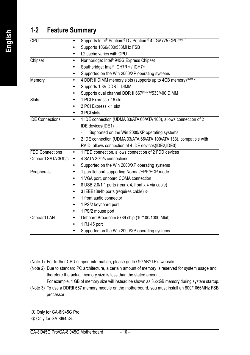
1-2 Feature Summary
CPU Supports Intel® Pentium® D / Pentium® 4 LGA775 CPU
Supports 1066/800/533MHz FSB
L2 cache varies with CPU
Chipset Northbridge: Intel® 945G Express Chipset
Southbridge: Intel® ICH7R / ICH7
Supported on the Win 2000/XP operating systems
Memory 4 DDR II DIMM memory slots (supports up to 4GB memory)
Supports 1.8V DDR II DIMM
Supports dual channel DDR II 667
(Note 3)
/533/400 DIMM
Slots 1 PCI Express x 16 slot
2 PCI Express x 1 slot
3 PCI slots
IDE Connections 1 IDE connection (UDMA 33/ATA 66/ATA 100), allows connection of 2
IDE devices(IDE1)
- Supported on the Win 2000/XP operating systems
2 IDE connection (UDMA 33/ATA 66/ATA 100/ATA 133), compatible with
RAID, allows connection of 4 IDE devices(IDE2,IDE3)
FDD Connections 1 FDD connection, allows connection of 2 FDD devices
Onboard SATA 3Gb/s 4 SATA 3Gb/s connections
Supported on the Win 2000/XP operating systems
Peripherals 1 parallel port supporting Normal/EPP/ECP mode
1 VGA port, onboard COMA connection
8 USB 2.0/1.1 ports (rear x 4, front x 4 via cable)
3 IEEE1394b ports (requires cable)
1 front audio connector
1 PS/2 keyboard port
1 PS/2 mouse port
Onboard LAN Onboard Broadcom 5789 chip (10/100/1000 Mbit)
1 RJ 45 port
Supported on the Win 2000/XP operating systems
(Note 1)
(Note 2)
(Note 1) For further CPU support information, please go to GIGABYTE's website.
(Note 2) Due to standard PC architecture, a certain amount of memory is reserved for system usage and
therefore the actual memory size is less than the stated amount.
For example, 4 GB of memory size will instead be shown as 3.xxGB memory during system startup.
(Note 3) To use a DDRII 667 memory module on the motherboard, you must install an 800/1066MHz FSB
processor .
Only for GA-8I945G Pro.
Only for GA-8I945G.
GA-8I945G Pro/GA-8I945G Motherboard - 10 -
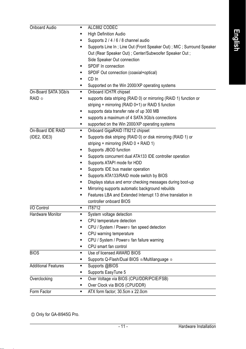
Onboard Audio ALC882 CODEC
High Definition Audio
Supports 2 / 4 / 6 / 8 channel audio
Supports Line In ; Line Out (Front Speaker Out) ; MIC ; Surround Speaker
Out (Rear Speaker Out) ; Center/Subwoofer Speaker Out ;
Side Speaker Out connection
SPDIF In connection
SPDIF Out connection (coaxial+optical)
CD In
Supported on the Win 2000/XP operating systems
On-Board SATA 3Gb/s Onboard ICH7R chipset
RAID
On-Board IDE RAID Onboard GigaRAID IT8212 chipset
(IDE2, IDE3) Supports disk striping (RAID 0) or disk mirroring (RAID 1) or
I/O Control IT8712
Hardware Monitor System voltage detection
BIOS Use of licensed AWARD BIOS
Additional Features Supports @BIOS
Overclocking Over Voltage via BIOS (CPU/DDR/PCIE/FSB)
Form Factor ATX form factor; 30.5cm x 22.0cm
supports data striping (RAID 0) or mirroring (RAID 1) function or
striping + mirroring (RAID 0+1) or RAID 5 function
supports data transfer rate of up 300 MB
supports a maximum of 4 SATA 3Gb/s connections
supported on the Win 2000/XP operating systems
striping + mirroring (RAID 0 + RAID 1)
Supports JBOD function
Supports concurrent dual ATA133 IDE controller operation
Supports ATAPI mode for HDD
Supports IDE bus master operation
Supports ATA133/RAID mode switch by BIOS
Displays status and error checking messages during boot-up
Mirroring supports automatic background rebuilds
Features LBA and Extended Interrupt 13 drive translation in
controller onboard BIOS
CPU temperature detection
CPU / System / Power
CPU warning temperature
CPU / System / Power fan failure warning
CPU smart fan control
Supports Q-Flash/Dual BIOS /Multilanguage
Supports EasyTune 5
Over Clock via BIOS (CPU/DDR)
fan speed detection
English
Only for GA-8I945G Pro.
Hardware Installation- 11 -
English
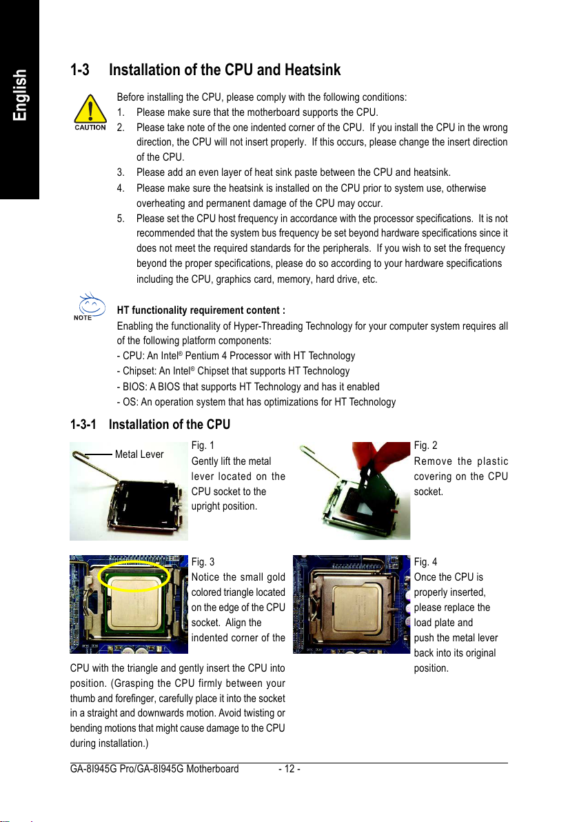
1-3 Installation of the CPU and Heatsink
Before installing the CPU, please comply with the following conditions:
1. Please make sure that the motherboard supports the CPU.
2. Please take note of the one indented corner of the CPU. If you install the CPU in the wrong
direction, the CPU will not insert properly. If this occurs, please change the insert direction
of the CPU.
3. Please add an even layer of heat sink paste between the CPU and heatsink.
4. Please make sure the heatsink is installed on the CPU prior to system use, otherwise
overheating and permanent damage of the CPU may occur.
5. Please set the CPU host frequency in accordance with the processor specifications. It is not
recommended that the system bus frequency be set beyond hardware specifications since it
does not meet the required standards for the peripherals. If you wish to set the frequency
beyond the proper specifications, please do so according to your hardware specifications
including the CPU, graphics card, memory, hard drive, etc.
HT functionality requirement content :
Enabling the functionality of Hyper-Threading Technology for your computer system requires all
of the following platform components:
- CPU: An Intel® Pentium 4 Processor with HT Technology
- Chipset: An Intel® Chipset that supports HT Technology
- BIOS: A BIOS that supports HT Technology and has it enabled
- OS: An operation system that has optimizations for HT Technology
1-3-1 Installation of the CPU
Metal Lever
Fig. 1
Gently lift the metal
lever located on the
CPU socket to the
upright position.
Fig. 2
Remove the plastic
covering on the CPU
socket.
Fig. 3
Notice the small gold
colored triangle located
on the edge of the CPU
socket. Align the
indented corner of the
CPU with the triangle and gently insert the CPU into
position. (Grasping the CPU firmly between your
thumb and forefinger, carefully place it into the socket
in a straight and downwards motion. Avoid twisting or
bending motions that might cause damage to the CPU
during installation.)
GA-8I945G Pro/GA-8I945G Motherboard - 12 -
Fig. 4
Once the CPU is
properly inserted,
please replace the
load plate and
push the metal lever
back into its original
position.
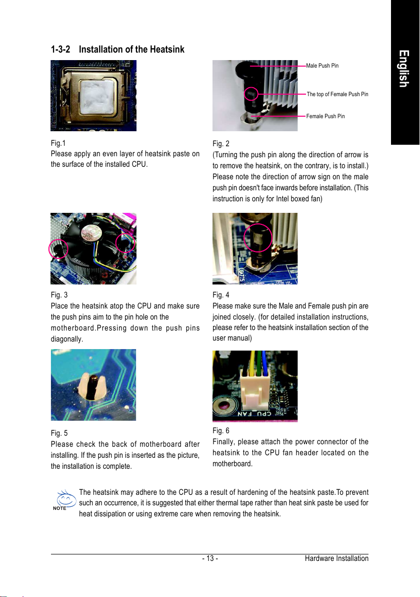
1-3-2 Installation of the Heatsink
English
Male Push Pin
The top of Female Push Pin
Female Push Pin
Fig.1
Please apply an even layer of heatsink paste on
the surface of the installed CPU.
Fig. 3
Place the heatsink atop the CPU and make sure
the push pins aim to the pin hole on the
motherboard.Pressing down the push pins
diagonally.
Fig. 5
Please check the back of motherboard after
installing. If the push pin is inserted as the picture,
the installation is complete.
Fig. 2
(Turning the push pin along the direction of arrow is
to remove the heatsink, on the contrary, is to install.)
Please note the direction of arrow sign on the male
push pin doesn't face inwards before installation. (This
instruction is only for Intel boxed fan)
Fig. 4
Please make sure the Male and Female push pin are
joined closely. (for detailed installation instructions,
please refer to the heatsink installation section of the
user manual)
Fig. 6
Finally, please attach the power connector of the
heatsink to the CPU fan header located on the
motherboard.
The heatsink may adhere to the CPU as a result of hardening of the heatsink paste.To prevent
such an occurrence, it is suggested that either thermal tape rather than heat sink paste be used for
heat dissipation or using extreme care when removing the heatsink.
Hardware Installation- 13 -

1-4 Installing/Removing Cool-Plus (Northbridge Cooling Fan)
English
Fig.1
To attach Cool-Plus to
a heatsink, align the
extensions on both
sides with the grooves
in the heatsink as
shown. Firmly press
down until it snaps into
position.
Fig.3
Before proceeding, first check to make sure that the fan's power cable is
disconnected. Then, while applying pressure to the top of the fan, carefully
use a screwdriver to dislodge the extension on one side.
Exerting too much pressure on the fan during removal might cause
the side extensions to break-off.
Fig.2
Once the fan is properly
affixed onto the
heatsink, plug the
power cable into the
NB_FAN connector.
1-5 Installation of Memory
Before installing the memory modules, please comply with the following conditions:
1. Please make sure that the memory used is supported by the motherboard. It is recommended that
memory of similar capacity, specifications and brand be used.
2. Before installing or removing memory modules, please make sure that the computer power is switched
off to prevent hardware damage.
3. Memory modules have a foolproof insertion design. A memory module can be installed in only one
direction. If you are unable to insert the module, please switch the direction.
The motherboard supports DDR II memory modules, whereby BIOS will automatically detect memory
capacity and specifications. Memory modules are designed so that they can be inserted only in one direction.
The memory capacity used can differ with each slot.
Only for GA-8I945G Pro.
GA-8I945G Pro/GA-8I945G Motherboard - 14 -
Notch
DDR II

Fig.1
The DIMM socket has a notch, so the DIMM memory module
can only fit in one direction. Insert the DIMM memory module
vertically into the DIMM socket. Then push it down.
Fig.2
Close the plastic clip at both edges of the DIMM sockets to
lock the DIMM module.
Reverse the installation steps when you wish to remove the
DIMM module.
Dual Channel Memory Configuration
GA-8I945G Pro/GA-8I945G supports the Dual Channel Technology. After oper-
ating the Dual Channel Technology, the bandwidth of Memory Bus will add double.
GA-8I945G Pro/GA-8I945G includes 4 DIMM sockets, and each Channel has
two DIMM sockets as following:
Channel A : DDR II 1, DDR II 2
Channel B : DDR II 3, DDR II 4
If you want to operate the Dual Channel Technology, please note the following explanations due
to the limitation of Intel chipset specifications.
1. Dual Channel mode will not be enabled if only one DDR II memory module is installed.
2. To enable Dual Channel mode with two or four memory modules (it is recommended to use
memory modules of identical brand, size, chips, and speed), you must install them into DIMM
sockets of the same color.
English
The following is a Dual Channel Memory configuration table: (DS: Double Side, SS: Single Side)
DDR II 1 DDR II 2 DDR II 3 DDR II 4
2 memory modules
4 memory modules
DS/SS X DS/SS X
X DS/SS X DS/SS
DS/SS DS/SS DS/SS DS/SS
Hardware Installation- 15 -
English
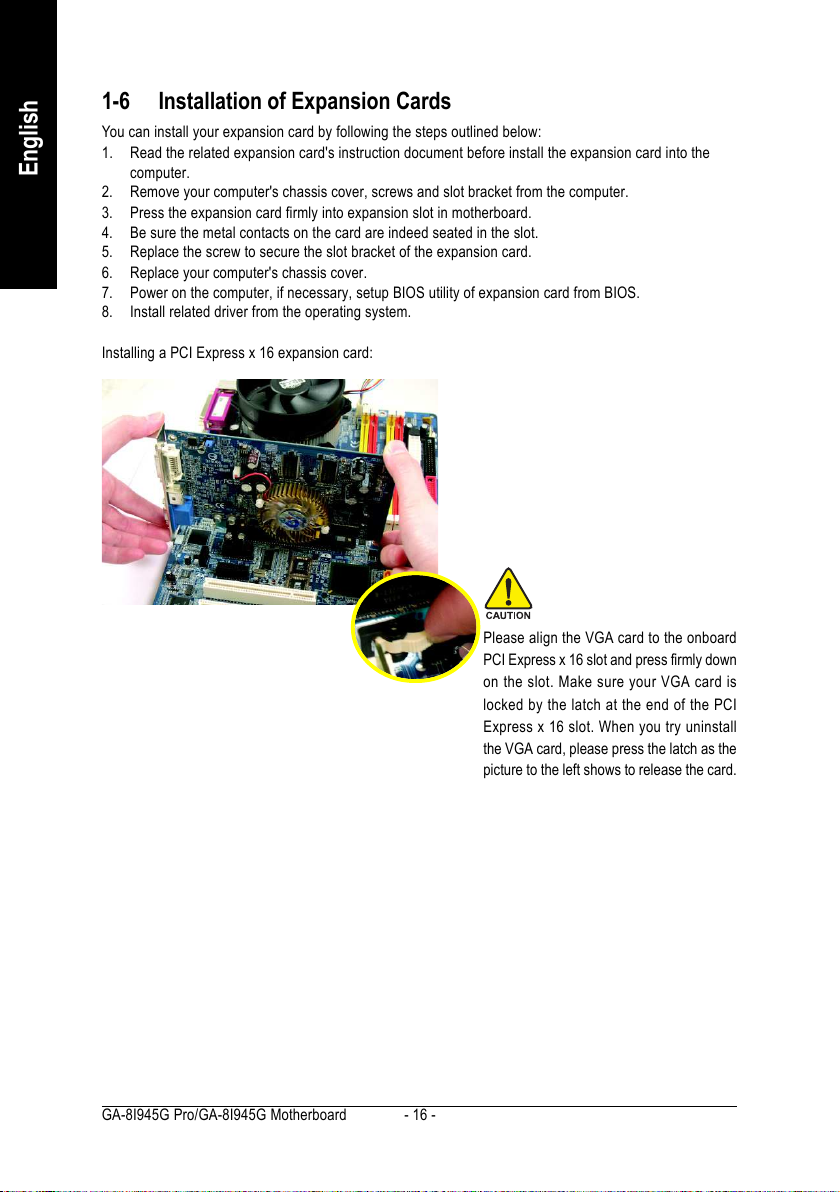
1-6 Installation of Expansion Cards
You can install your expansion card by following the steps outlined below:
1. Read the related expansion card's instruction document before install the expansion card into the
computer.
2. Remove your computer's chassis cover, screws and slot bracket from the computer.
3. Press the expansion card firmly into expansion slot in motherboard.
4. Be sure the metal contacts on the card are indeed seated in the slot.
5. Replace the screw to secure the slot bracket of the expansion card.
6. Replace your computer's chassis cover.
7. Power on the computer, if necessary, setup BIOS utility of expansion card from BIOS.
8. Install related driver from the operating system.
Installing a PCI Express x 16 expansion card:
Please align the VGA card to the onboard
PCI Express x 16 slot and press firmly down
on the slot. Make sure your VGA card is
locked by the latch at the end of the PCI
Express x 16 slot. When you try uninstall
the VGA card, please press the latch as the
picture to the left shows to release the card.
GA-8I945G Pro/GA-8I945G Motherboard - 16 -
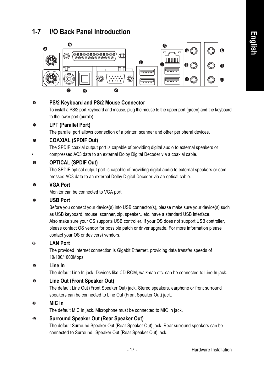
1-7 I/O Back Panel Introduction
PS/2 Keyboard and PS/2 Mouse Connector
To install a PS/2 port keyboard and mouse, plug the mouse to the upper port (green) and the keyboard
to the lower port (purple).
LPT (Parallel Port)
The parallel port allows connection of a printer, scanner and other peripheral devices.
COAXIAL (SPDIF Out)
The SPDIF coaxial output port is capable of providing digital audio to external speakers or
• compressed AC3 data to an external Dolby Digital Decoder via a coaxial cable.
OPTICAL (SPDIF Out)
The SPDIF optical output port is capable of providing digital audio to external speakers or com
pressed AC3 data to an external Dolby Digital Decoder via an optical cable.
VGA Port
Monitor can be connected to VGA port.
USB Port
Before you connect your device(s) into USB connector(s), please make sure your device(s) such
as USB keyboard, mouse, scanner, zip, speaker...etc. have a standard USB interface.
Also make sure your OS supports USB controller. If your OS does not support USB controller,
please contact OS vendor for possible patch or driver upgrade. For more information please
contact your OS or device(s) vendors.
LAN Port
The provided Internet connection is Gigabit Ethernet, providing data transfer speeds of
10/100/1000Mbps.
Line In
The default Line In jack. Devices like CD-ROM, walkman etc. can be connected to Line In jack.
Line Out (Front Speaker Out)
The default Line Out (Front Speaker Out) jack. Stereo speakers, earphone or front surround
speakers can be connected to Line Out (Front Speaker Out) jack.
MIC In
The default MIC In jack. Microphone must be connected to MIC In jack.
Surround Speaker Out (Rear Speaker Out)
The default Surround Speaker Out (Rear Speaker Out) jack. Rear surround speakers can be
connected to Surround Speaker Out (Rear Speaker Out) jack.
English
Hardware Installation- 17 -
English
Center/Subwoofer Speaker Out
The default Center/Subwoofer Speaker Out jack. Center/Subwoofer speakers can be connected to
Center/Subwoofer Speaker Out jack.
Side Speaker Out
The default Side Speaker Out jack. Surround side speakers can be connected to Side Speaker Out
jack.
In addition to the default speakers settings, the ~ audio jacks can be reconfigured to perform
different functions via the audio software. Only microphones still MUST be connected to the de-
fault Mic In jack ( ) . Please refer to the 2-/4-/6-/8- channel audio setup steps for detailed software
configuration information.
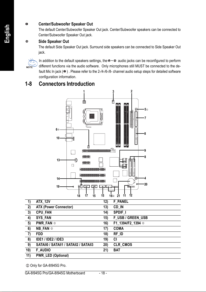
1-8 Connectors Introduction
13
2
5
7
6
10
13
14
19
17
18
15
15
1) ATX_12V
2) ATX (Power Connector)
3) CPU_FAN
4) SYS_FAN
5) PWR_FAN
6) NB_FAN
7) FDD
8) IDE1 / IDE2 / IDE3
9) SATAII0 / SATAII1 / SATAII2 / SATAII3
10) F_AUDIO
11) PWR_LED (Optional)
Only for GA-8I945G Pro.
GA-8I945G Pro/GA-8I945G Motherboard - 18 -
12
11
16
21
12) F_PANEL
13) CD_IN
14) SPDIF_I
15) F_USB / GREEN_USB
16) F1_1394/F2_1394
17) COMA
18) RF_ID
19) CI
20) CLR_CMOS
21) BAT
8
9
8
4
20
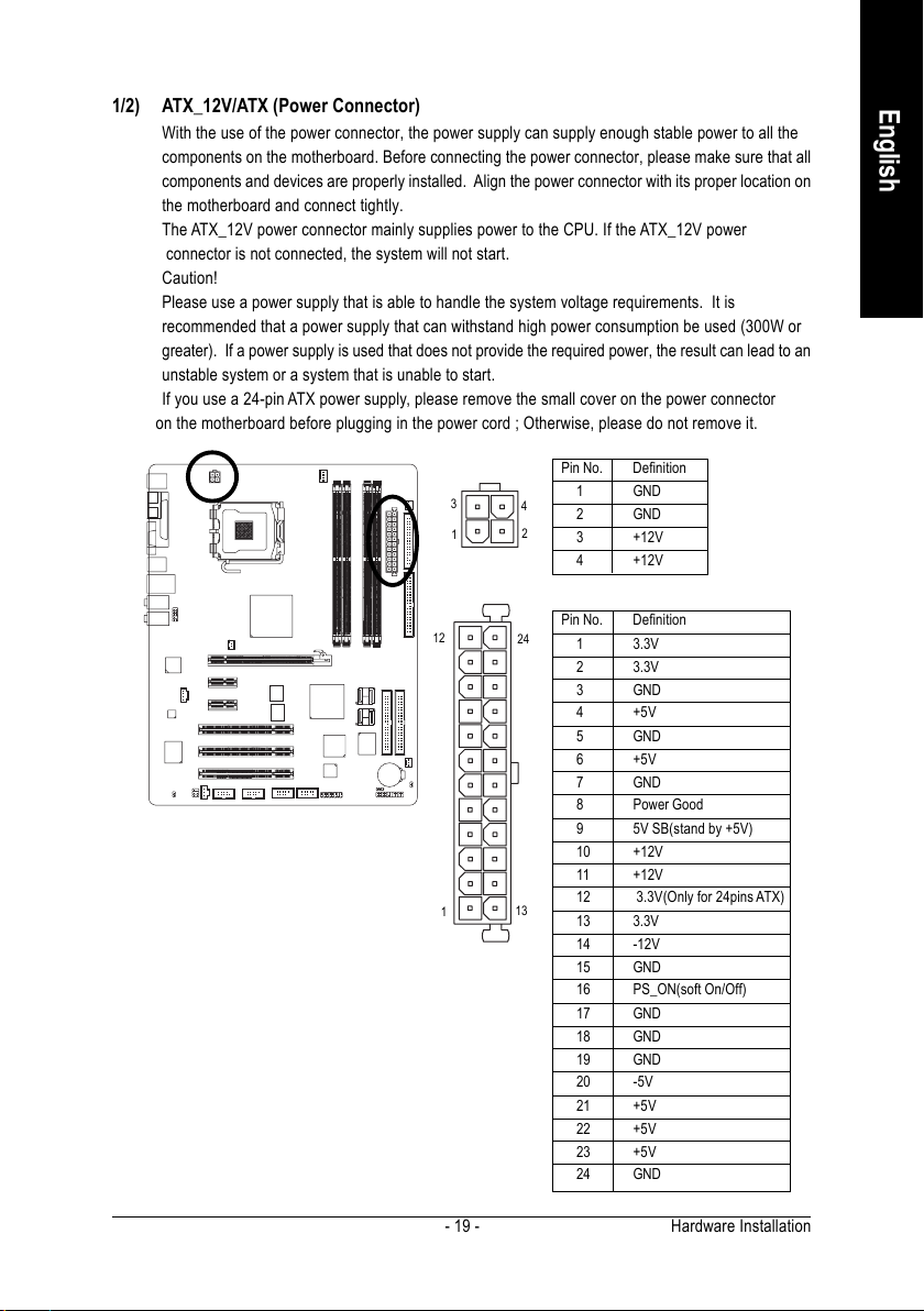
1/2) ATX_12V/ATX (Power Connector)
With the use of the power connector, the power supply can supply enough stable power to all the
components on the motherboard. Before connecting the power connector, please make sure that all
components and devices are properly installed. Align the power connector with its proper location on
the motherboard and connect tightly.
The ATX_12V power connector mainly supplies power to the CPU. If the ATX_12V power
connector is not connected, the system will not start.
Caution!
Please use a power supply that is able to handle the system voltage requirements. It is
recommended that a power supply that can withstand high power consumption be used (300W or
greater). If a power supply is used that does not provide the required power, the result can lead to an
unstable system or a system that is unable to start.
If you use a 24-pin ATX power supply, please remove the small cover on the power connector
on the motherboard before plugging in the power cord ; Otherwise, please do not remove it.
Pin No. Definition
3
1
4
2
1 GND
2 GND
3 +12V
4 +12V
English
12
1
Pin No. Definition
24
1 3.3V
2 3.3V
3 GND
4 +5V
5 GND
6 +5V
7 GND
8 Power Good
9 5V SB(stand by +5V)
10 +12V
11 +12V
12 3.3V(Only for 24pins ATX)
13
13 3.3V
14 -12V
15 GND
16 PS_ON(soft On/Off)
17 GND
18 GND
19 GND
20 -5V
21 +5V
22 +5V
23 +5V
24 GND
Hardware Installation- 19 -
English
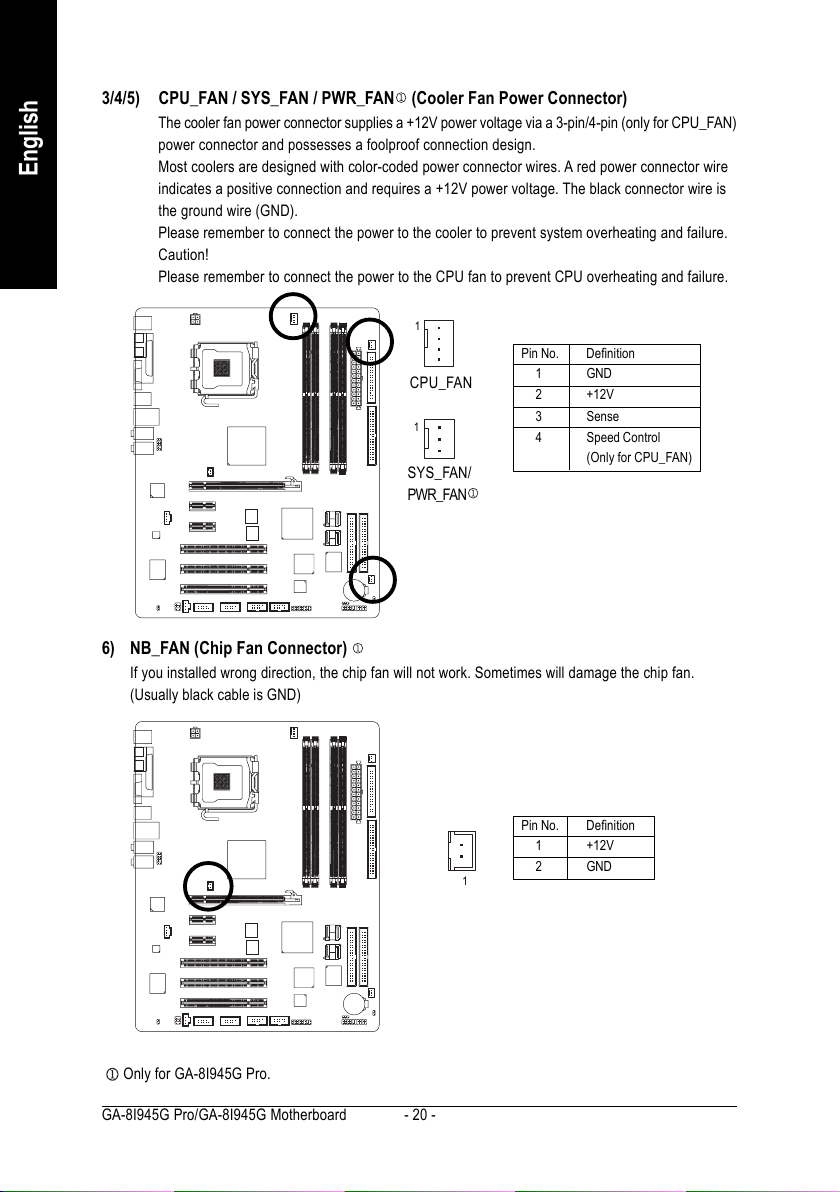
3/4/5) CPU_FAN / SYS_FAN / PWR_FAN (Cooler Fan Power Connector)
The cooler fan power connector supplies a +12V power voltage via a 3-pin/4-pin (only for CPU_FAN)
power connector and possesses a foolproof connection design.
Most coolers are designed with color-coded power connector wires. A red power connector wire
indicates a positive connection and requires a +12V power voltage. The black connector wire is
the ground wire (GND).
Please remember to connect the power to the cooler to prevent system overheating and failure.
Caution!
Please remember to connect the power to the CPU fan to prevent CPU overheating and failure.
1
Pin No. Definition
CPU_FAN
1
SYS_FAN/
1 GND
2 +12V
3 Sense
4 Speed Control
(Only for CPU_FAN)
PWR_FAN
6) NB_FAN (Chip Fan Connector)
If you installed wrong direction, the chip fan will not work. Sometimes will damage the chip fan.
(Usually black cable is GND)
Only for GA-8I945G Pro.
GA-8I945G Pro/GA-8I945G Motherboard - 20 -
1
Pin No. Definition
1 +12V
2 GND
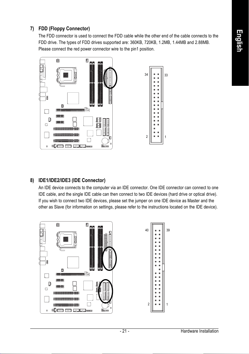
7) FDD (Floppy Connector)
The FDD connector is used to connect the FDD cable while the other end of the cable connects to the
FDD drive. The types of FDD drives supported are: 360KB, 720KB, 1.2MB, 1.44MB and 2.88MB.
Please connect the red power connector wire to the pin1 position.
English
34
2
33
1
8) IDE1/IDE2/IDE3 (IDE Connector)
An IDE device connects to the computer via an IDE connector. One IDE connector can connect to one
IDE cable, and the single IDE cable can then connect to two IDE devices (hard drive or optical drive).
If you wish to connect two IDE devices, please set the jumper on one IDE device as Master and the
other as Slave (for information on settings, please refer to the instructions located on the IDE device).
3940
2
1
Hardware Installation- 21 -
English
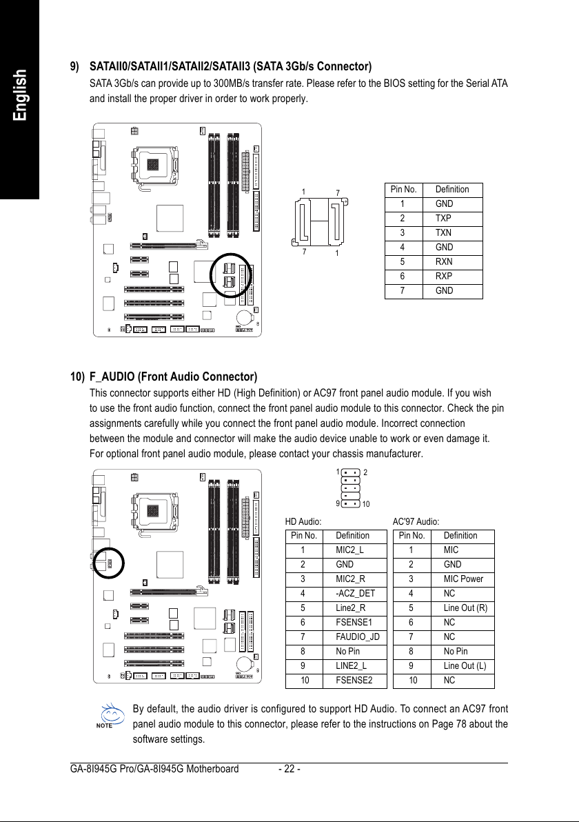
9) SATAII0/SATAII1/SATAII2/SATAII3 (SATA 3Gb/s Connector)
SATA 3Gb/s can provide up to 300MB/s transfer rate. Please refer to the BIOS setting for the Serial ATA
and install the proper driver in order to work properly.
1
7
7
1
Pin No. Definition
1 GND
2 TXP
3 TXN
4 GND
5RXN
6 RXP
7 GND
10) F_AUDIO (Front Audio Connector)
This connector supports either HD (High Definition) or AC97 front panel audio module. If you wish
to use the front audio function, connect the front panel audio module to this connector. Check the pin
assignments carefully while you connect the front panel audio module. Incorrect connection
between the module and connector will make the audio device unable to work or even damage it.
For optional front panel audio module, please contact your chassis manufacturer.
1
2
9
10
HD Audio: AC'97 Audio:
Pin No. Definition
1 MIC2_L
2 GND
3 MIC2_R
4 -ACZ_DET
5 Line2_R
6 FSENSE1
7 FAUDIO_JD
8 No Pin
9 LINE2_L
10 FSENSE2
Pin No. Definition
1 MIC
2 GND
3 MIC Power
4NC
5 Line Out (R)
6NC
7NC
8 No Pin
9 Line Out (L)
10 NC
By default, the audio driver is configured to support HD Audio. To connect an AC97 front
panel audio module to this connector, please refer to the instructions on Page 78 about the
software settings.
GA-8I945G Pro/GA-8I945G Motherboard - 22 -
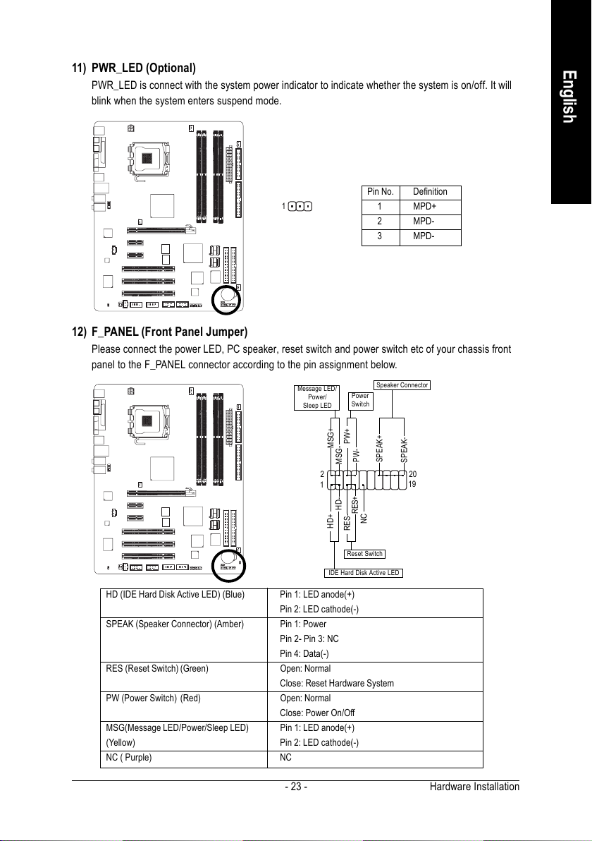
11) PWR_LED (Optional)
PWR_LED is connect with the system power indicator to indicate whether the system is on/off. It will
blink when the system enters suspend mode.
Pin No. Definition
1
1 MPD+
2 MPD-
3 MPD-
12) F_PANEL (Front Panel Jumper)
Please connect the power LED, PC speaker, reset switch and power switch etc of your chassis front
panel to the F_PANEL connector according to the pin assignment below.
MSG-
HD-
Power
Switch
PW+
RES-
PW-
RES+
Speaker Connector
SPEAK+
NC
SPEAK-
20
19
Message LED/
Power/
Sleep LED
2
1
MSG+
HD+
English
Reset Switch
IDE Hard Disk Active LED
HD (IDE Hard Disk Active LED) (Blue) Pin 1: LED anode(+)
Pin 2: LED cathode(-)
SPEAK (Speaker Connector) (Amber) Pin 1: Power
Pin 2- Pin 3: NC
Pin 4: Data(-)
RES (Reset Switch) (Green) Open: Normal
Close: Reset Hardware System
PW (Power Switch) (Red) Open: Normal
Close: Power On/Off
MSG(Message LED/Power/Sleep LED) Pin 1: LED anode(+)
(Yellow) Pin 2: LED cathode(-)
NC ( Purple) NC
Hardware Installation- 23 -
English
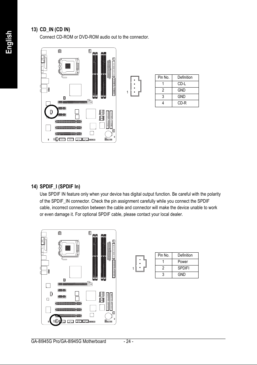
13) CD_IN (CD IN)
Connect CD-ROM or DVD-ROM audio out to the connector.
Pin No. Definition
1 CD-L
1
2 GND
3 GND
4 CD-R
14) SPDIF_I (SPDIF In)
Use SPDIF IN feature only when your device has digital output function. Be careful with the polarity
of the SPDIF_IN connector. Check the pin assignment carefully while you connect the SPDIF
cable, incorrect connection between the cable and connector will make the device unable to work
or even damage it. For optional SPDIF cable, please contact your local dealer.
GA-8I945G Pro/GA-8I945G Motherboard - 24 -
Pin No. Definition
1 Power
1
2 SPDIFI
3 GND
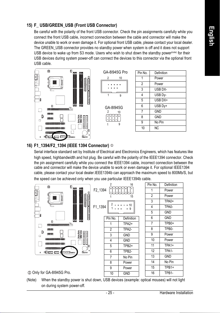
15) F_ USB/GREEN_USB (Front USB Connector)
Be careful with the polarity of the front USB connector. Check the pin assignments carefully while you
connect the front USB cable, incorrect connection between the cable and connector will make the
device unable to work or even damage it. For optional front USB cable, please contact your local dealer.
The GREEN_USB connector provides no standby power when system is off and it does not support
USB device to wake up from S3 mode. Users who wish to shut down the standby power
(note)
for their
USB devices during system power-off can connect the devices to this connector via the optional front
USB cable.
GA-8I945G Pro
2910
1
GA-8I945G
2
10
9
1
Pin No. Definition
1 Power
2 Power
3 USB DX-
4 USB Dy-
5 USB DX+
6 USB Dy+
7 GND
8 GND
9 No Pin
10 NC
16) F1_1394/F2_1394 (IEEE 1394 Connector)
Serial interface standard set by Institute of Electrical and Electronics Engineers, which has features like
high speed, highbandwidth and hot plug. Be careful with the polarity of the IEEE1394 connector. Check
the pin assignment carefully while you connect the IEEE1394 cable, incorrect connection between the
cable and connector will make the device unable to work or even damage it. For optional IEEE1394
cable, please contact your local dealer.IEEE1394b can approach the maximum speed to 800Mb/S, but
the speed can be achieved only when you use particular IEEE1394b cable.
2
F2_1394
1
F1_1394
Only for GA-8I945G Pro.
2
1
Pin No. Definition
1 TPA2+
2 TPA2-
3 GND
4 GND
5 TPB2+
6 TPB2-
7 No Pin
8 Power
9 Power
10 GND
(Note) When the standby power is shut down, USB devices (example: optical mouses) will not light
on during system power-off.
16
15
10
9
Pin No. Definition
1 Power
2 Power
3 TPA0+
4 TPA0-
5 GND
6 GND
7 TPB0+
8 TPB0-
9 Power
10 Power
11 TPA1+
12 TPA1-
13 GND
14 No Pin
15 TPB1+
16 TPB1-
Hardware Installation- 25 -
English
English
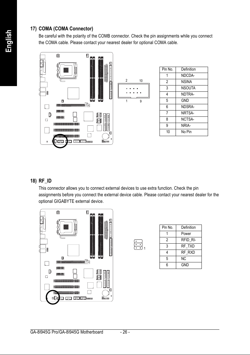
17) COMA (COMA Connector)
Be careful with the polarity of the COMB connector. Check the pin assignments while you connect
the COMA cable. Please contact your nearest dealer for optional COMA cable.
Pin No. Definition
2
10
1
9
1 NDCDA-
2 NSINA
3 NSOUTA
4 NDTRA-
5 GND
6 NDSRA-
7 NRTSA-
8 NCTSA-
9 NRIA-
10 No Pin
18) RF_ID
This connector allows you to connect external devices to use extra function. Check the pin
assignments before you connect the external device cable. Please contact your nearest dealer for the
optional GIGABYTE external device.
GA-8I945G Pro/GA-8I945G Motherboard - 26 -
1
Pin No. Definition
1 Power
2 RFID_RI-
3 RF_TXD
4 RF_RXD
5NC
6 GND
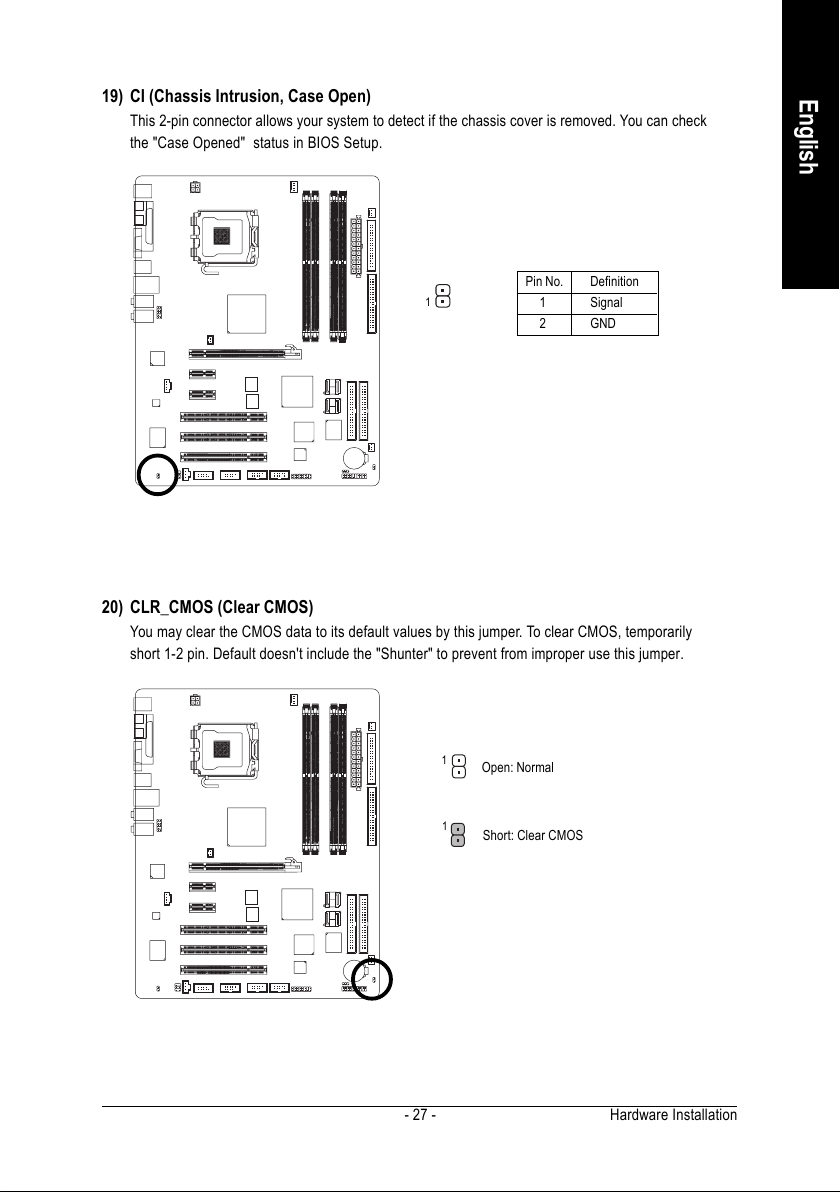
19) CI (Chassis Intrusion, Case Open)
This 2-pin connector allows your system to detect if the chassis cover is removed. You can check
the "Case Opened" status in BIOS Setup.
Pin No. Definition
1
1 Signal
2 GND
20) CLR_CMOS (Clear CMOS)
You may clear the CMOS data to its default values by this jumper. To clear CMOS, temporarily
short 1-2 pin. Default doesn't include the "Shunter" to prevent from improper use this jumper.
English
1
Open: Normal
1
Short: Clear CMOS
Hardware Installation- 27 -
 Loading...