

Page 1

GA-8I915G Pro
Intel® Pentium® 4 LGA775 Processor Motherboard
User's Manual
Rev. 1002
12ME-8I915GP-1002
Page 2

Jun.11, 2004
GA-8I915G Pro
Motherboard
Jun. 11, 2004
Motherboard
GA-8I915G Pro
Page 3

Copyright
© 2004 GIGA-BYTE TECHNOLOGY CO., LTD. All rights reserved.
The trademarks mentioned in the manual are legally registered to their respective companies.
Notice
The written content provided with this product is the property of Gigabyte.
No part of this manual may be reproduced, copied, translated, or transmitted in any form or by any
means without Gigabyte's prior written permission. Specifications and features are subject to
change without prior notice.
Product Manual Classification
In order to assist in the use of this product, Gigabyte has categorized the user manual in the
following:
n For quick installation, please refer to the "Hardware Installation Guide" included with the
product.
n For detailed product information and specifications, please carefully read the
"Product User Manual".
n For detailed information related to Gigabyte's unique features, please go to Gigabyte's
website under "Technology Guide" where information can be downloaded in .pdf format.
Fore more product details, please click onto Gigabyte's website at www.gigabyte.com.tw
Page 4

Table of Contents
GA-8I915G Pro Motherboard Layout ..........................................................................6
Block Diagram ...........................................................................................................7
Chapter 1 Hardware Installation ..................................................................................9
1-1 Considerations Prior to Installation .........................................................................9
1-2 Feature Summary .................................................................................................10
1-3 Installation of the CPU and Heatsink ................................................................... 12
1-3-1 Installation of the CPU .................................................................................... 12
1-3-2 Installation of the He atsink ..............................................................................13
1-4 Installation of Memory...........................................................................................14
1-5 Install expansion cards .........................................................................................16
1-6 I/O Back Panel Introduction ................................................................................. 17
1-7 Connectors Introduction ........................................................................................ 18
Chapter 2 BIOS Setup ............................................................................................ 29
The Main Menu (For example: BIOS Ver. : F3) ............................................................30
2-1 Standard CMOS Features ................................................................................... 32
2-2 Advanced BIOS Features....................................................................................34
2-3 Integrated Peripherals ...........................................................................................36
2-4 Power Management Setup ...................................................................................39
2-5 PnP/PCI Configurations ....................................................................................... 41
2-6 PC Health Status ..................................................................................................42
2-7 MB Intelligent Tweaker(M.I.T.) .............................................................................43
2-8 Load Fail-Safe Defaults ......................................................................................... 45
2-9 Load Optimized Defaults ....................................................................................... 45
2-10 Set Supervisor/User Password .......................................................................... 46
2-11 Save & Exit Setup ...............................................................................................47
2-12 Exit Without Saving .............................................................................................. 47
Chapter 3 Drivers Installation ................................................................................... 49
3-1 Install Chipset Drivers ..........................................................................................49
3-2 Software Applications ............................................................................................ 50
3-3 Driver CD Information ........................................................................................... 50
3-4 Hardware Information ........................................................................................... 51
3-5 Contact Us ............................................................................................................ 51
Chapter 4 Appendix ............................................................................................... 55
- 4 -
Page 5

4-1 Unique Software Utilities ...................................................................................... 55
4-1-1 Xpre ss R ecove ry Introduc tion .......................................................................56
4-1-2 Flash B IOS Method Introduction .................................................................... 59
4-1-4 2 / 4 / 5.1 / 7.1 Ch annel Audi o Func tion Introduction .................................. 70
4-2 Troubleshooting......................................................................................................76
- 5 -
Page 6
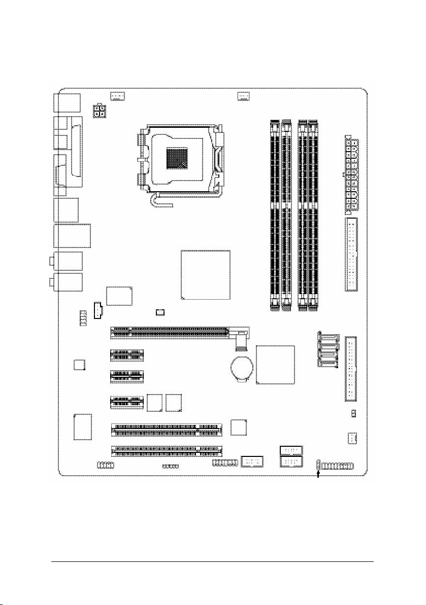
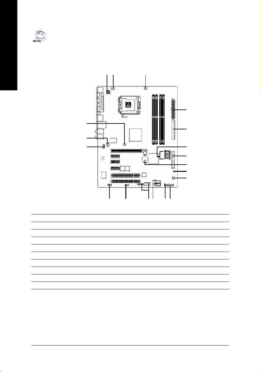
GA-8I915G Pro Motherboard Layout
SPDIF _OUT
SPDIF_IN
KB_MS
VGA
USB
USB
AUD IO1
AUD IO2
CODEC
ATX_12 V
LPT
LAN
AZALIA_FP
CD_IN
Ma rve ll
8 001
CPU _FAN
PCI E_1
PCI E_2
NB_ FAN
LGA 775
Intel 9 15G
PC IE_16
PWR_FAN
DDR1
GA-8I915G Pro
Intel IC H6
BAT
DDR2
DDR3
S_ATA4
S_ATA3
S_ATA2
S_ATA1
DDR4
ATX
IDE
FD D
IT8712
COM A
PCI E_3
BACK
BIOS
MAIN
BIOS
TSB43AB 23
PCI1
PCI2
IR
F2 _1 39 4 F 1_ 139 4
F_U SB2
F_U SB1
CLR_ CM OS
SYS_FAN
F_PAN EL
PWR _LED
- 6 -
Page 7
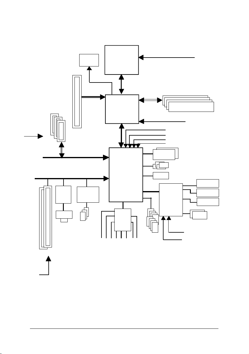
Block Diagram
PCI-E CLK
(100MHz)
PCI-E CLK
(100MHz)
3 PCI E xpressx 1 Ports
PCI Express x 1 Bus
Marvell
8001
RJ45
2 PCI
VGA
PCI Express x16
PCI Bus
TSB43AB23
3 IEEE1394
LGA775
Proce ssor
Intel
915G
GMCH
Intel
ICH6
CODEC
MIC
Line-Out
CPUCLK+ /-(200/1 33MH z)
Host
Interface
GMCHCLK (200/133MHz)
Dual BIOS
8 USB
Ports
Line-In
SPDIF In
SPDIF Out
DDR 400/333MHz DIMM
Dual Channel Mem ory
66MHz
33MHz
14.318MHz
48MHz
4 Serial ATA
ATA33/66/100
IDE Channels
IT 8712
24MHz
33MHz
LPT Port
COM Port
PS/2 KB/Mouse
Floppy
PCICLK
(33MHz)
Surround Speaker Out
Back Surround Speaker Out
Center/Subwoofer Speaker Out
- 7 -
Page 8

- 8 -
Page 9

Chapter 1 Hardware Installation
1-1 Considerations Prior to Installation
Preparing Your Computer
The motherboard contains numerous delicate electronic circuits and components which can
become damaged as a result of electrostatic discharge (ESD). Thus, prior to installation, please
follow the instructions below:
1. Please turn off the computer and unplug its power cord.
2. When handling the motherboard, avoid touching any metal leads or connectors.
3. It is best to wear an electrostatic discharge (ESD) cuff when handling electronic components
(CPU, RAM).
4. Prior to installing the electronic components, please have these items on top of an antistatic pad or
within a electrostatic shielding container.
5. Please verify that you the power supply is switched off before unplugging the power supply connector
from the motherboard.
Installation Notices
1. Prior to installation, please do not remove the stickers on the motherboard. These stickers are required
for warranty validation.
2. Prior to the installation of the motherboard or any hardware, please first carefully read the information
in the provided manual.
3. Before using the product, please verify that all cables and power connectors are connected.
4. To prevent damage to the motherboard, please do not allow screws to come in contact with the
motherboard circuit or its components.
5. Please make sure there are no leftover screws or metal components placed on the motherboard or
within the computer casing.
6. Please do not place the computer system on an uneven surface.
7. Turning on the computer power during the installation process can lead to damage to system
components as well as physical harm to the user.
8. If you are uncertain about any installation steps or have a problem related to the use of the product,
please consult a certified computer technician.
English
Instances of Non-Warranty
1. Damage due to natural disaster, accident or human cause.
2. Damage as a result of violating the conditions recommended in the user manual.
3. Damage due to improper installation.
4. Damage due to use of uncertified components.
5. Damage due to use exceeding the permitted parameters.
6. Product determined to be an unofficial Gigabyte product.
Hardware Installation- 9 -
Page 10

English
1-2 Feature Summary
CP U w Supports the latest Intel® Pe ntium® 4 LGA77 5 CPU
w Supports 800/533MHz FSB
w L2 cache var ies with CPU
Chip set w Northbridge : Intel® 915G Ex press Chips et
w Southbridge: Intel® ICH6
Memory w 4 DDR DIMM memory slots (supports up to 4GB mem ory)
w Supports dual channel DDR400/333 DIMM
w Supports 2.5V DDR DIMM
Slots w 1 PC I Expr ess x 16 slo t
w 3 P CI Exp res s x 1 slots
w 2 PCI slots
IDE Connections w 1 IDE connection (UDMA 33/ATA 66/ATA 100), allows connection of 2
IDE devices
FDD Connections w 1 FDD connection, allows connection of 2 FDD devices
Onboard SATA w 4 Serial ATA connections
Peripherals w 1 parallel port supporting Normal/EPP/ECP mode
w 1 VGA port, onboard COMA connection
w 8 USB 2.0/1.1 ports (rear x 4, front x 4 via cable)
w 3 IEEE1394 ports (requires cable)
w 1 front audio connector
w 1 IR connector
w 1 PS/2 keyboard port
w 1 PS/2 mouse port
Onboard LAN w Onboard Marvell 8001 chip (10/100/1000 Mbit)
w 1 RJ 45 port
Onboard Audio w C-Media 9880 CODEC (UAJ)
w Supports Jack Sensing function
w Supports 2 / 4 / 5.1 / 7. 1 chan nel aud io
w Supports Li ne In ; Line Out ; MIC ; Back S urround Sp eaker Out ;
Center/Su bwoofer Speake r O ut ; Surro und Spe aker Out conn ection
w Supports SPDIF In/Out connection
w CD In
(Note 1)
(Note 1) Due to standard PC architecture, a certain amount of memory is reserved for system usage and
therefore the actual memory size is less than the stated amount.
For example, 4 GB of memory size will instead be shown as 3.xxGB memory during system startup.
GA-8I915G Pro Motherboard - 10 -
Page 11

I/O Control w IT8712
Hardware Monitor w CPU / System / Power fan speed detection
w CPU tempe rature detection
w System voltag e detection
w CPU / Sy stem / Power fan failu re warni ng
w CPU Sm art FAN Control
BIOS w Use of licens ed AWA RD BIOS
w Supports Dual BIOS/Q-Flash
Additional Features w Supports @BIOS
w Supports EasyTune
Overclocking w Over Voltage via BIOS (CPU/DDR/PCI-E)
w Over Cloc k via BIOS (CPU/D DR)
Form Factor w ATX form factor; 30.5cm x 24.4cm
English
Hardware Installation- 11 -
Page 12
1-3 Installation of the CPU and Heatsink
English
Before installing the CPU, plea se comply with the following conditions:
1. Please make sure that the motherboard supports the CPU.
2. Please take note of the one indented corner of the CPU. If you install the CPU in the wrong
direction, the CPU will not insert properly. If this occurs, please change the insert direction
of the CPU.
3. Please add an even layer of heat sink paste between the CPU and heatsink.
4. Please ma ke sure the heatsink is installed on the CPU prior to system use, otherwise
overheating and permanent damage of the CPU may occur.
5. Please set the CPU host frequency in accordance with the processor specifications. It is not
recomm ended that the system bus frequency be set beyond hardware specifications since it
does not meet the required standards for the peripherals. If you wish to set the frequency
beyond the proper specifications, please do so according to your hardware specifications
inclu ding the C PU, gr aphic s card , mem ory, hard drive, etc.
HT fu nctio nality re quir ement c ontent :
Enabling the functionality of Hyper-Threading Technology for your comp uter system requires all
of the following platform com ponents:
- CPU: An Intel® Pentium 4 Processor with HT Tec hnology
- Chipset: An Intel® Chipset that supports HT Technology
- BIOS: A BIOS that supports HT Tech nology and has it enabled
- OS: An operation system that has optimizations for HT Technology
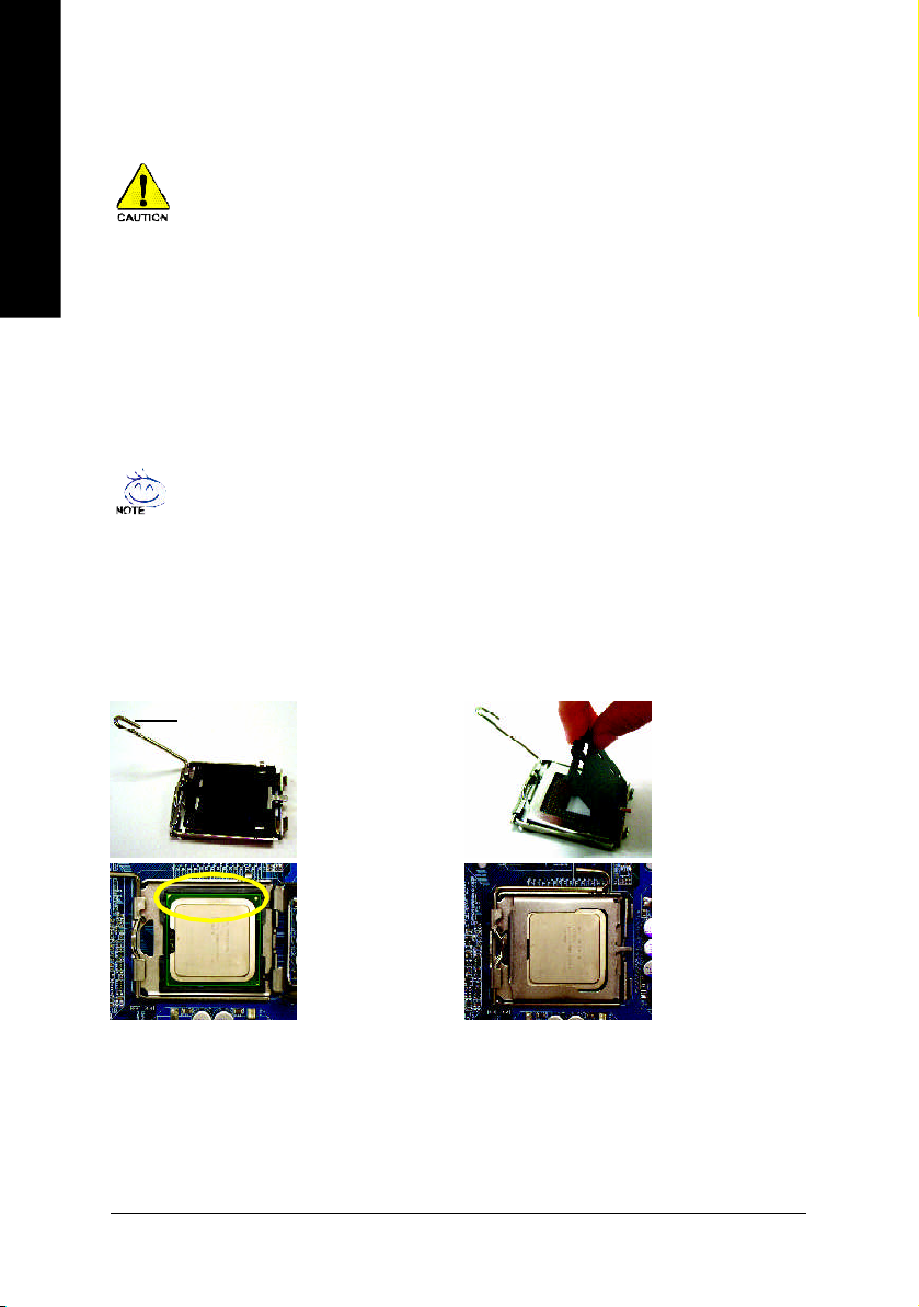
1-3-1 Installation of the CPU
Me tal Lever
Fig . 1
Gently li ft the metal
le ver lo cate d on the
CPU sock et to the
upright pos ition.
Fig . 2
Re m ov e the pl as tic
cov erin g on the CPU
soc ket.
Fig . 3
Notice the sm all gold
co lo r ed tria ng l e lo cated o n the edge o f
th e CP U s oc k e t.
Align the
inde nted c orne r of the CPU with the tria ngle a nd
gently inser t the CP U into pos ition. (Gr asping the
CPU fi rm ly be tween y our thu m b and forefing er,
care fully plac e it into the s ocke t in a straig ht and
do wnwar ds m oti on. Avo id twisti ng or bend in g
motions that might cause d amag e to the CPU during in stallation.)
GA-8I915G Pro Motherboard - 12 -
Fig . 4
Once the CPU i s
prope rly i nserted,
please replace the
plastic cover ing and
push the m etal lever
back i nto its or iginal
positio n.
Page 13
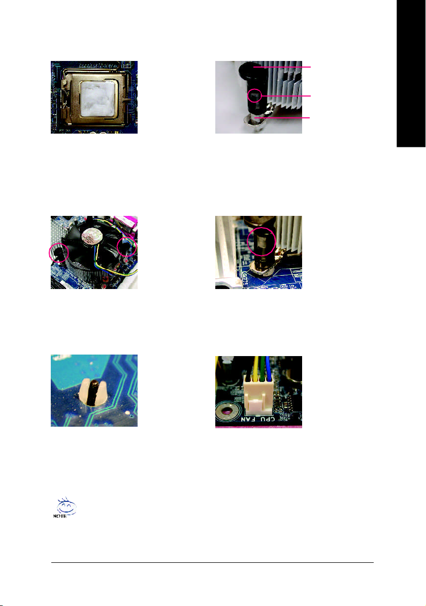
1-3-2 Installation of the Heatsink
English
Ma le Pus h Pin
The top of Female P ush P in
Fema le P ush Pin
Fig.1
Please apply an e ven layer of heatsink paste on
the sur face o f the in stalled CPU.
Fig . 3
Place the hea tsink atop the CPU and m ake sure
the push p ins aim to the p in hole on the
m oth er bo ar d. Pr es si ng do wn the pu sh pin s
diag onall y.
Fig . 5
Pl eas e ch eck the back of m othe rbo ard after
installing. If the push pin is inserted as the picture,
the installation is com plete.
Fig . 2
(Turn ing the pu sh pin alo ng the dir ection of arrow
is to r em ove the heatsi nk, on the c ontrar y, is to
install .)
Please no te the dire ction of arrow sign on the male
push pin doesn't face in wards b efore instal lation.
(This instruc tion i s onl y for Intel boxed fan)
Fig . 4
Please make sure the M ale and F emal e push p in
ar e joi n ed cl ose ly . (fo r de tail ed i nsta llation
instructions, please r efer to the heatsink ins tallation
section of the u ser m anual)
Fig . 6
Fina lly, plea se attach the power con nector of the
hea tsin k to the C PU fan head er loca ted on the
motherboard.
The heatsink m ay adh ere to the CPU as a res ult of hardening of the heatsink paste.To prevent
such an occurrence, it is suggested that either therm al tape rather than heat sink paste be used
for heat dissi pation or using extrem e care when rem oving the h eatsink.
Hardware Installation- 13 -
Page 14
English
1-4 Installation of Memory
Bef ore ins talli ng the memory mod ules , ple ase comply wit h t he fol lowin g cond itions:
1 . Ple ase mak e sure t hat t he memo ry used is suppor ted by the mothe rboa rd. It is recommend ed that
me mory of si mi l a r c a pa ci ty , s pe ci fi ca ti on s an d br an d be u se d.
2 . Be fo re i ns ta ll in g or r em ov in g mem ory modu le s, p le as e m ake su re tha t th e co mp ut er
p ow er i s s wi t c he d o ff t o p re ve nt ha rd wa re da ma ge .
3 . M em or y m odul es h av e a f oo lp roo f inse r ti on d es i g n. A m emo ry mod u le c a n be
in stall ed in o nly on e d irect ion . If yo u ar e un a ble to ins er t th e m odul e, p le ase swi tch t he
di re ct io n.
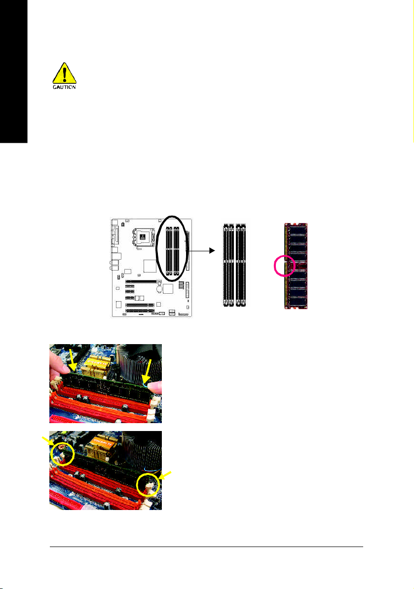
The m otherboard has 4 dual inline mem ory module (DIMM ) sockets. The BIOS will automatically detects
mem ory type and size. To install the mem ory module, just push it vertically into the DIMM socket. The DIMM
module can only fit in one direction due to the notch. Mem ory size can vary between sockets.
Notch
DDR
Fig.1
The DIMM socket has a notch, so the DIMM m emory module can
only fit in one direction. Insert the DIMM memory module vertically
into the DIMM socket. Then push it down.
Fig.2
Close the plastic cli p at both edges o f the DIMM sockets to lock
the DIMM module.
Reverse the installation steps when you wish to remove the DIMM
module.
GA-8I915G Pro Motherboard - 14 -
Page 15

Dual Channel DDR
GA-8I915G Pro su pports the Dual Ch annel Technolo gy. After oper ating the D ual Cha nnel Technolog y,
the ban dwidth o f Mem ory Bus will add double up to 6.4GB/s.
GA-8I91 5G Pro inclu des 4 DIM M socke ts, and each Cha nnel h as two D IMM soc kets a s followin g:
Chann el A : DDR 1, DDR 2
Chann el B : DDR 3, DDR 4
If you wan t to operate the Dua l Chan nel Technology, p lease no te the following explanation s due
to the lim itation of Intel c hipset spe cifications.
1. One/three DDR m em ory modu le is i nstalled: T he Dual Channel Technology can't opera te
when on ly one DD R mem ory module is installed.
2. Two DDR mem ory modules are installed (the same memory size and type): The Dual
Chan nel Techno logy will opera te when two mem ory m odules are inserted individually into
Channe l A and B. If you install two mem ory modules in the same channel, the Dual Channel
Tech nolo gy will n ot oper ate.
3. Four D DR m emo ry modu les are installed : If you in stall four m em ory m odule s at the sa me
time, the Dual Channe l Technolo gy will ope rate onl y when those mod ules have the sa me
me mo ry s ize and type.
We'll strongly re com men d our user to slot two DDR m em ory m odules into the DIMMs with the same
color in o rder for Du al Cha nnel Techno logy to work.
The foll owing table is for Dual C hannel Technolog y com bina tion:
l Dual Channel Technology (DS: Double Side, SS: Single Side)
2 mem ory modules
4 mem ory modules
DDR 1 DDR 2 DDR 3 DDR 4
DS/SS X DS/SS X
X DS/SS X DS/SS
DS/SS DS/SS DS/SS DS/SS
English
Hardware Installation- 15 -
Page 16
English
1-5 Install expansion cards
You can install your expansion card by following the steps outlined below:
1. Read the related expansion card's instruction document before install the expansion card into the
computer.
2. Remove your computer's chassis cover, screws and slot bracket from the computer.
3. Press the expansion card firmly into expansion slot in motherboard.
4. Be sure the metal contacts on the card are indeed seated in the slot.
5. Replace the screw to secure the slot bracket of the expansion card.
6. Replace your computer's chassis cover.
7. Power on the compu ter, if necessary, setup BIOS utility of expansion card from BIOS.
8. Install related driver from the operating system.
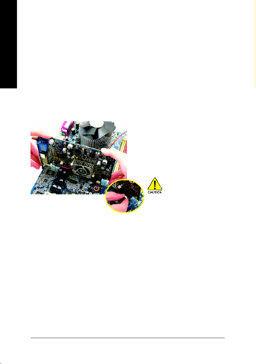
Installi ng a PCI Expr ess x 1 6 expan sion car d:
Pleas e carefull y p ull ou t the sm all whitedrawable bar at the end of the P CI
Expre ss x 1 6 s lot when yo u try to install/
Unins tall the VGA ca rd. Pl ease alig n the
VGA card to the o nboar d PCI Expre ss x
16 slo t and pres s firm ly d own on the sl ot
.M ake s ure your VGA card is locked by
the sm all white-d rawable bar.
GA-8I915G Pro Motherboard - 16 -
Page 17
1-6 I/O Back Panel Introduction
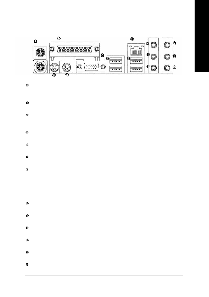
PS/2 Keyboard and PS/2 Mouse Connector
To install a PS/2 port keyboard and mouse, plug the mouse to the upper port (green) and the keyboard to the
lower port (purple).
Parallel Port
The parallel port allows connection of a printer, scanner and other peripheral devices.
SPDIF_O (SPDIF Out)
The SPDIF output is capable of providing digital audio to external speakers or compressed AC3 data to
an external Dolby Digital Decoder.
SPDIF_I (SPDIF In)
Use SPDIF In feature only when your device has d igital output function.
VGA Port
Monitor can be connected to VGA port.
LAN Port
The provided Internet connection is Gigabit Ethernet, providing data transfer speeds of 10/100/1000Mbps.
USB port
Before you connect your device(s) into USB connector(s), please make sure your device(s) such as
USB keyboard, mouse, scanner, zip, speaker...etc. have a standard USB interface. Also make sure
your OS supports USB controller. If your OS does not support USB controller, please contact OS ven
dor for possible patch or driver upgrade. For more information please contact your OS or device(s)
vendors.
Line In
Devices like CD-ROM, walkman etc. can be connected to Line In jack.
Line Out (Front Speaker Out)
Connect the stereo speakers, earphone or front surround channels to this connector.
MIC In
Microphone can be connected to MIC In jack.
Back Surround Speaker Out
Connect the back surround channels to this connector.
Center/Subwoofer Speaker Out
Connect the Center/Subwoofer channels to this connector.
Surround Speaker Out
Connec t the surroun d chann els to this conn ector.
Hardware Installation- 17 -
English
Page 18
English
You can u se a udio so ftware to configu re 2 -/4-/5 .1-/7.1 -channe l audio functioning.
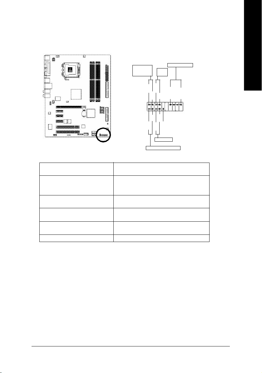
1-7 Connectors Introduction
1
3
6
13
12
5
151617
14
10
2
8
9
7
19
18
4
11
1) ATX_12V
2) ATX (Power Connector)
3) CPU_FAN
4) SYS_FAN
5) PWR_FAN
6) NB_FAN
7) FDD
8) IDE
9) S_ATA1/S_ATA2/S_ATA3/S_ATA4
10) PWR_LED
GA-8I915G Pro Motherboard - 18 -
11) F_PANEL
12) AZALIA_FP
13) CD_IN
14) F_USB1 / F_USB2
15) F1_1394 / F2_1394
16) IR
17) COMA
18) CLR_CMOS
19) BAT
Page 19
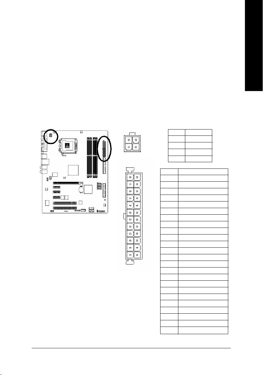
1/2) ATX_12V/ATX (Power Connector)
With the use of the power connector, the power supply can supply enough stable power to all the
components on the motherboard. Before connecting the power connector, please make sure that all
components and devices are properly installed. Align the power connector with its proper location on
the mo therboard and connect tightly.
The ATX_12V power connector mainly supplies power to the CPU. If the ATX_12V power connector
is not connected, the system will not start.
Caution!
Please use a power supply that is able to handle the system voltage requirements. It is
recomm ended that a power supply that can withstand high power consumption be used (300W or
greater). If a power supply is used that does not provide the required power, the result can lead to an
unstable system or a system that is unable to start.
Please remove the sticker on the motherboard before plugging in while the ATX power supplier is 24
pins; Otherwise, please do not remove it.
Pin No. Definition
3
1
1 3
2 4
4
2
1
1 2
1 GND
2 GND
3 +12V
4 +12V
Pin No. Definition
1 3.3V
2 3.3V
3 GND
4 VCC
5 GND
6 VCC
7 GND
8 Power Good
9 5V SB(stand by +5V)
10 +12V
11 +12V
12 3.3V(Only for 24pins ATX)
13 3.3V
14 -12V
15 GND
16 PS_ON(soft On/Off)
17 GND
18 GND
19 GND
20 -5V
21 VCC
22 VCC
23 VCC
24 GND
English
Hardware Installation- 19 -
Page 20
English
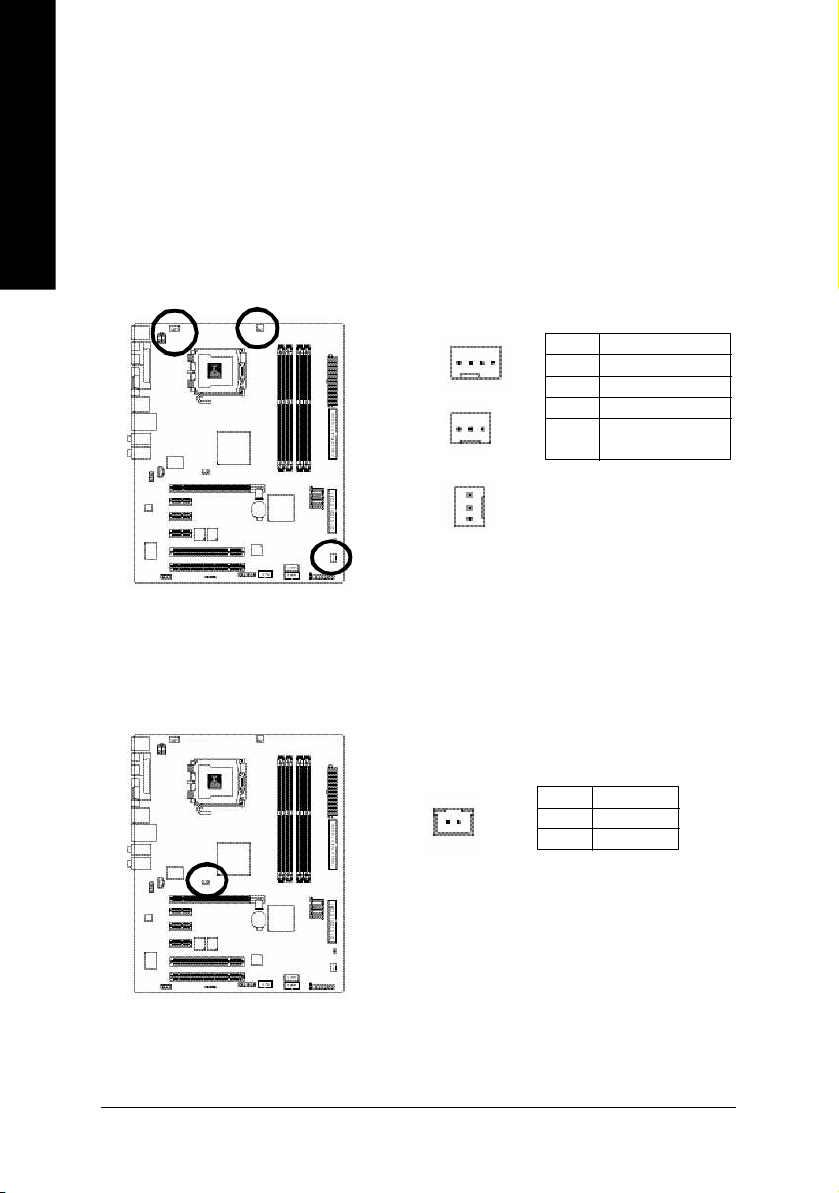
3/4/5) CPU_FAN / SYS_FAN / PWR_FAN (Cooler Fan Power Connector)
The c ooler fan p ower con nector suppl ies a +12V power voltage via a 3- pin/4- pin (onl y for
CPU_F AN) p ower conn ector and p ossess es a ful -proof conne ction de sign.
Mo st coole rs are de signe d with c olor-c oded p ower con nector wires. A red po wer conn ector
wire indica tes a positive conne ction and re quires a +12V power voltage. The blac k connec tor
wire is the grou nd wire (G ND).
Pleas e rem em ber to conne ct the power to the cool er to pre vent sy stem o verhea ting and
failure.
Cautio n! Please rem emb er to conn ect the power to the CPU fan to prevent CP U overh eating
and failure.
1
Pin No. Definition
1 GND
2 +12V
3 Sense
4 Speed Control
(Only for CPU_FAN)
1
CPU_FAN
PWR_FAN
1
SYS_FAN
6) NB_FAN (Chip Fan Connector)
If you installed wrong direction, the chip fan will not work. Som etimes will damage the chip fan.
(Usually black cable is GND)
Pin No. Definition
1
1 +12V
2 GND
GA-8I915G Pro Motherboard - 20 -
Page 21
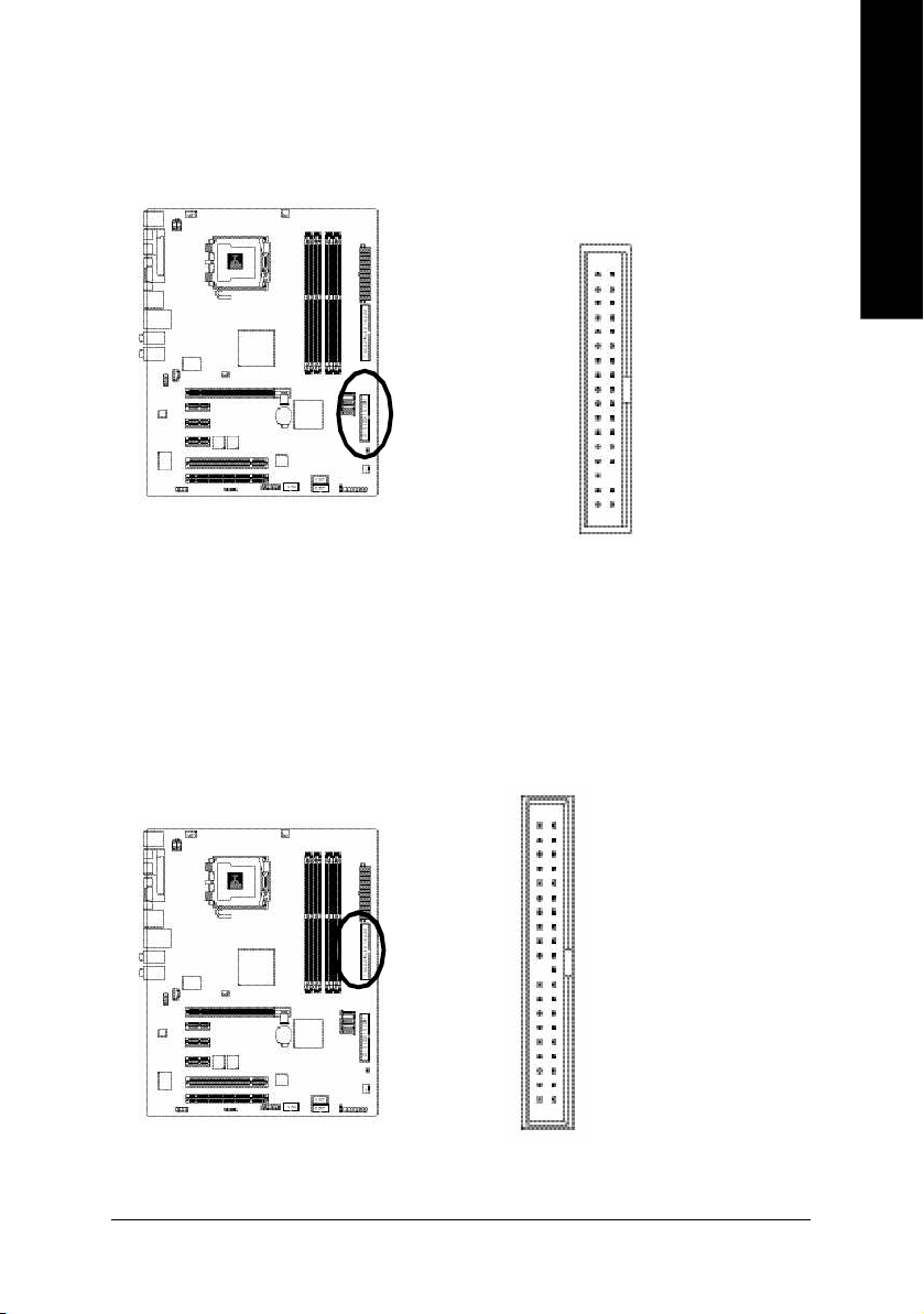
7) FDD (FDD Connector)
The FDD connector is used to connect the FDD cable while the other end of the cable connects to the
FDD drive. The types of FDD drives supported are:360KB, 720KB, 1.2MB, 1.44MB and 2.88MB.
Please connect the red power connector wire to the pin1 position.
3 33 4
12
8) IDE (IDE Connector)
An IDE device connects to the computer via an IDE connector. One IDE connector can connect to one
IDE cable, and the single IDE cable can then connect to two IDE devices (hard drive or optical drive). If
you wish to connect two IDE devices, please set the jumper on one IDE device as Master and the other
as Slave(for information on settings, please refer to the instructions located on the IDE device).
English
4 0 3 9
2 1
Hardware Installation- 21 -
Page 22
English
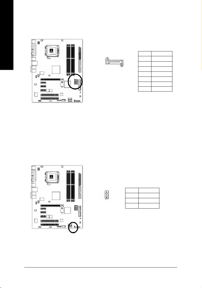
9) S_ATA1/S_ATA2/S_ATA3/S_ATA4(Serial ATA Connector, Controlled by ICH6)
Seria l ATA can provid e 150M B/s transfer rate. Plea se refer to the BIOS se tting for the Se rial ATA
and i nstall the prop er dri ver in order to work p roperl y.
Pin No. Definition
7 1
S_ATA
(C ontrol by IC H6)
1 GND
2 TXP
3 TXN
4 GND
5 RXN
6 RXP
7 GND
10) PWR_LED
PWR_LED is connect with the system power indicator to indicate whether the system is on/off. It will
blink when the system enters suspend mode.
GA-8I915G Pro Motherboard - 22 -
Pin No. Definition
1
1 MPD+
2 MPD-
3 MPD-
Page 23
11) F_PANEL (Front Panel Jumper)
Please connect the power LED, PC peaker, reset switch and power switch etc of your chassis front
panel to the F_PANEL connector according to the pin assignment below.
English
Message LED/
Powe r/
Sleep L ED
Power
Swit ch
PW+
MSG+
PW-
MSG-
2
1
HD-
RES+
HD+
RES-
Reset Swit ch
IDE Hard Disk Act ive L ED
HD (IDE Hard Disk Active LED) Pin 1: LED anode(+)
(Blue) Pin 2: LED cathode(-)
SPEAK ( Speaker Connector) Pin 1: VCC(+)
(Amber) Pin 2- Pin 3: NC
Pin 4: Data(-)
RES (Reset Switch) Open: Normal Operation
(Green) Close: Reset Hardware System
PW (Power Switch) Open: Normal Operation
(Red) Close: Power On/Off
MSG(M essage LED/Power/Sleep LED) Pin 1: LED anode(+)
(Yellow) Pin 2: LED cathode(-)
NC( Purple) NC
Speaker Connec tor
SPEAK+
NC
SPEAK-
2 0
1 9
Hardware Installation- 23 -
Page 24

English
12) AZALIA_FP (Front Audio Panel Connector)
Please make sure the pin assigment on the cable is the same as the pin assigment on the MB header.
To find out if the chassis you are buying support front audio panel connector, please contact your dealer.
Pin No. Definition
1 MIC2_L
91 0
1
2
2 GND
3 MIC2_R
4 -ACZ_DET
5 Line2_R
6 FSENSE1
7 FAUOIO_JD
8 No Pin
9 LINE2_L
10 FSENSE2
13) CD_IN (CD IN, Black)
Connect CD-ROM or DVD-ROM audio out to the connector.
1
GA-8I915G Pro Motherboard - 24 -
Pin No. Definition
1 CD-L
2 GND
3 GND
4 CD-R
Page 25

14) F1_USB / F2_USB (Front USB Connector, Yellow )
Be careful with the polarity of the front USB connector. Check the pin assignment carefully while
you connect the front USB cable, incorrect connection between the cable and connector will make
the device unable to work or even damag e it. For optional front USB cable, please contact your
local d ealer.
The " USB Devi ce Wa ke up From S3" is only su pported by re ar USB p orts.
2
1 0
1
9
Pin No. Definition
1 Power
2 Power
3 USB0 DX-
4 USB1 Dy-
5 USB0 DX+
6 USB1 Dy+
7 GND
8 GND
9 No Pin
10 NC
15) F1_1394/F2_1394 (IEEE 1394 Connector)
Serial interface standard set by Institute of Electrical and Electronics Engineers, which has features like
high speed, high bandwidth and hot plug.
Be careful with the polarity of the IEEE1394 connector. Check the pin assignment carefully while you
connect the IEEE1394 cable, incorrect connection between the cable and connector will make the
device unable to work or even damage it. For optional IEEE1394 cable, please contact your local
dealer. 2
Pin No. Definition
1
F2_1394
1 TPA2+
2 TPA2-
3 GND
4 GND
5 TPB2+
6 TPB2-
7 No Pin
8 Power
9 Power
10 GND
2
1
F1_1394
1 6
Pin No. Definition
1 5
1 0
9
1 Power
2 Power
3 TPA0+
4 TPA05 GND
6 GND
7 TPB0+
8 TPB0-
9 Power
10 Power
11 TPA1+
12 TPA113 GND
14 No Pin
15 TPB1+
16 TPB1-
English
Hardware Installation- 25 -
Page 26

English
16) IR
Be careful with the polarity of the IR connector while you connect the IR. Please contact you
nearest dealer for optional IR device.
Pin No. Definition
1 VCC
1
2 No Pin
3 IR RX
4 GND
5 IR TX
17) COMA (COM A Connector)
Be careful with the polarity of the COMA connector. Check the pin assignme nt while you connect
the COMA cable. Please contact your nearest dealer for optional COMA cable.
GA-8I915G Pro Motherboard - 26 -
2
1 9
Pin No. Definition
1 NDCDA-
1 0
2 NSINA
3 NSOUTA
4 NDTRA-
5 GND
6 NDSRA-
7 NRTSA-
8 NCTSA-
9 NRIA-
10 No Pin
Page 27

18) CLR_CMOS (Clear CMOS)
You may clear the CMOS data to its default values by this jumper. To clear CM OS, temporarily
short 1-2 pin. Default doesn't include the "Shunter" to prevent from improper use this jumper.
Open: Normal
1
Short: Clear CMOS
1
19) BAT(Battery)
English
Danger of explosion if battery is incorrectly replaced.
Replace only with the same or equivalent type
recom mended by the manufacturer.
Dispose of used batteries according to the manufac turer's
instructions.
If you want to erase CMOS...
1.Turn OFF the computer and unplug the power cord.
2.Remo ve the battery, wait for 30 sec ond.
3.Re-install the battery.
4.Plug the power cord and turn ON the com puter.
Hardware Installation- 27 -
Page 28

English
GA-8I915G Pro Motherboard - 28 -
Page 29

Chapter 2 BIOS Setup
BIOS (Basic Input and Output System) includes a CMOS SETUP utility which allows user to configure
required settings or to activate certain system features.
The CMOS SETUP sav es the configuration in the CMOS SRAM of the motherboard.
When the pow er is turned off, the battery on the motherboard supplies the necessary power to the CMOS
SRAM.
When the pow er is turned on, pushing the <Del> button during the BIOS POST (Power-On Self Test) w ill
take you to the CMOS SETUP screen. You can enter the BIOS setup screen by pressing "Ctrl + F1".
When setting up BIOS for the first time, it is recommended that y ou save the current BIOS to a disk in the
event that BIOS needs to be reset to its original settings. If you wish to upgrade to a new BIOS, either
Gigabyte's Q-Flash or @BIOS utility can be used.
Q-Flash allows the user to quickly and easily update or backup BIOS without entering the operating system.
@BIOS is a Window s-based utility that does not require users to boot to DOS before u pgrading BIOS but
directly download and update BIOS from the Internet.
CONTROL KEYS
< >< >< >< > Move to select item
<Enter> Select Item
<Esc> Main Menu - Quit and not save changes into CMOS Status Page Setup Menu
and Option Page Setup Menu - Exit current page and return to Main Menu
<Page Up> Increase the numeric v alue or make changes
<Page Down> Decrease the numeric value or make changes
<F1> General help, only for Status Page Setup Menu and Option Page Setup Menu
<F2> Item Help
<F5> Restore the previous CMOS value from CMOS, only for Option Page Setup Menu
<F6> Load the file-safe default CMOS v alue from BIOS default table
<F7> Load the Optimized Defaults
<F8> Dual BIOS/Q-Flash utility
<F9> Sy stem Information
<F10> Save all the CMOS changes, only for Main Menu
English
Main Menu
The on-line description of the highlighted setup function is displayed at the bottom of the screen.
Status Page Setup Menu / Option P age Setup Menu
Press F1 to pop up a small help window that describes the appropriate keys to use and the possible selections for the highlighted item. To exit the Help Window press <Esc>.
BIOS Setup- 29 -
Page 30

English
The Main Menu (For example: BIOS Ver. : F3)
Once y ou enter Aw ard BIOS CMOS Setup Utility, the Main Menu (as figure below) w i ll appear on the
screen. Use arrow keys to select among the items and press <En ter> to accept or enter the sub-menu.
CMOS Setup Utility-Copy right (C) 1984-2004 Award S oftware
} Standard CMOS Features
} Advanc ed BIOS Features
} Integrated Peripherals
} Power Management Setup
} PnP /PCI Configurations
} PC Health St atus
} MB Intelligent Tweaker(M.I.T.)
ESC: Quit higf: Selec t Item
F8: Dual BIOS/Q- Flash F10: Save & Exit S etup
Time, Date, Hard Disk Ty pe...
If y ou can't find the setting you want, please press "Ctrl+F1" to search the advanced option hidden.
n Standard CM OS Features
This setup page includes all the items in standard compatible BIOS.
n Adva nced BIOS Feat ures
This setup page includes all the items of Award special enhanced features.
n Integrated Periphe rals
This setup page includes all onboard peripherals.
n Power Manag ement S etup
This setup page includes all the items of Green function features.
n PnP/PCI Configuration
This setup page includes all the configurations of PCI & PnP ISA resources.
n PC Health St atus
This setup page is the System auto detect Temperature, voltage, fan, speed.
n MB Intelligent Tweaker(M. I.T.)
This setup page is control CPU clock and frequency ratio.
n Load Fail -Safe Defaults
Fail-Safe Defaults indicates the value of the system parameters which the system would be in safe
configuration.
n Load Optimiz ed Defa ults
Optimized Defaults indicates the value of the sy stem parameters which the system w ould be in best
performance c onfiguration.
Load Fail-Safe Defaults
Load Optimized Defaults
Set Supervisor Password
Set User Password
Save & Exit Setup
Exit Without Saving
GA-8I915G Pro Mothe rboard - 30 -
Page 31

n Set Supervisor Pa ssword
Change, set, or disable password. It allows you to limit access to the sy stem and Setup, or just to Setup.
n Set User Pass word
Change, set, or disable passw ord. It allows you to limit access to the system.
n Save & Exit Setup
Save CMOS value settings to CMOS and exit setup.
n Exit Without Sav ing
Abandon all CMOS value changes and exit setup.
English
BIOS Setup- 31 -
Page 32

English
2-1 Standard CMOS Features
CMOS Setup Utility-Copy right (C) 1984-2004 Award S oftware
Date (mm:dd:y y) Thu, Apr 29 2004
Time (hh:mm:ss) 22:31:24
} IDE C hannel 0 Master [None]
} IDE C hannel 0 Slave [None]
Drive A [1.44M, 3.5"]
Drive B [None]
Floppy 3 Mode S uport [Disabled]
Holt On [All, But Keyboard]
Base Memory 640K
Extended Mem ory 127M
Total Memory 128M
higf: Move Enter: Select +/-/PU/P D: Value F10: Save ESC: Ex it F1: Gene ral Help
F5: Previous Values F6: Fail-Save Default F7: Optimized De faults
Date
The date format is <week>, <month>, <day>, <y ear>.
Week The w eek, from Sun to Sat, determined by the BIOS and is display only
Month The month, Jan. Through Dec.
Day The day, from 1 to 31 (or the maximum allowed in the month)
Year The year, from 1999 through 2098
Time
The times format in <hour> <minute> <second>. The time is calculated base on the 24-hour
military-time clock. For example, 1 p.m. is 13:00:00.
IDE Channel 0 Master, Slav e
IDE HDD Auto-Detection Press "Enter" to select this option for automatic device detection.
IDE Channel 0 Master(Slave) IDE Device Setup. You can use one of three methods:
Auto Allows BIOS to automatically detect IDE devices during POST(default)
None Select this if no IDE devices are used and the system will skip the automatic
detection step and allow for faster system start up.
Manual User can manually input the correct settings
Access Mode Use this to set the access mode for the hard drive. The four options are:
CHS/LBA/Large/Auto(default:Auto)
Hard drive information should be labeled on the outside drive casing. Enter the appropriate option
based on this information.
Cylinder Number of cylinders
Head Number of heads
Precomp Write precomp
Landing Zone Landing zone
Sector Number of sectors
If a hard disk has not been installed, select NONE and press <Enter>.
Standard CMOS Features
Item Help
Menu Level}
Change the day, month,
year
<Week>
Sun. to Sa t.
<Month>
Jan. to Dec.
<Day>
1 to 31 (or maximum
allowe d in the m onth)
<Year>
1999 to 2098
GA-8I915G Pro Mothe rboard - 32 -
Page 33

Drive A / Drive B
The category identifies the ty pes of floppy disk drive A or drive B that has been installed in the computer.
None No floppy drive installed
360K, 5.25" 5.25 inch PC-type standard drive; 360K byte capacity.
1.2M, 5.25" 5.25 inch AT-type high-density drive; 1.2M by te capacity
(3.5 inch w hen 3 Mode is Enabled).
720K, 3.5" 3.5 inch double-sided drive; 720K byte capacity
1.44M, 3.5" 3.5 inch double-sided drive; 1.44M byte capacity.
2.88M, 3.5" 3.5 inch double-sided drive; 2.88M byte capacity.
Floppy 3 Mode Suppo rt (for Japan Area)
Disabled Normal Floppy Drive. (Default v alue)
Drive AA Drive A is 3 mode Floppy Drive.
Drive B Drive B is 3 mode Floppy Drive.
Both Drive A & B are 3 mode Floppy Drives.
Halt on
The category determines whether the computer will stop if an error is detected during power up.
No Errors The system boot will not stop for any error that may be detected and you
will be prompted.
All Errors Whenever the BIOS detects a non-fatal error the sy stem will be stopped.
All, But Key board The system boot will not stop for a keyboard error; it will stop for all other
errors. (Default value)
All, But Disk ette The system boot will not stop for a disk error; it will stop for all other errors.
All, But Disk/Key The system boot will not stop for a keyboard or disk error; it will stop for all
other errors.
Memory
The category is display-only which is determined by POST (Power On Self Test) of the BIOS.
Base Memo ry
The POST of the BIOS w ill determine the amount of base (or conv entional) memory installed
in the system.
The value of the base memory is typically 512K for systems w ith 512K memory installed on
the motherboard, or 640K for sy stems with 640K or more memory installed on the motherboard.
Extended Memo ry
The BIOS determines how much ex tended memory is present during the POST.
This is the amount of memory located abov e 1 MB i n the CPU's memory address map.
Total Memory
This item displays the memory s ize that used.
English
BIOS Setup- 33 -
Page 34

English
2-2 Advanced BIOS Features
CMOS Setup Utility-Copy right (C) 1984-2004 Award S oftware
} Hard Disk Bo ot Prio rity [Press Enter]
First Boot De vice [Floppy]
Second Boot Device [Hard Disk]
Third Boot Device [CDROM]
Password C heck [Set up]
# CPU H y per-Thre ading [Enabled]
Limit CP UID Max. to 3 [Enabled]
On-Chip Frame Buffer Size [8MB]
higf: Move Enter: Select +/-/PU/P D: Value F10: Save ESC: Ex it F1: Gene ral Help
F5: Previous Values F6: Fail-Save Default F7: Optimized De faults
" # " System w ill detect automatically and show up when you install the Intel® Pentium® 4
processor with HT Technology.
Hard Disk Boot Priority
Select boot sequence for onboard(or add-on cards) SCSI, RAID, etc.
Use < > or < > to select a device, then press<+> to move it up, or <-> to mov e it down the list. Press
<ESC> to ex it this menu.
First / Second / Third Boot Dev ice
Floppy Select y our boot device priority by Floppy.
LS120 Select your boot dev ice priority by LS120.
Hard Disk Select your boot dev ice priority by Hard Disk.
CDROM Select your boot device priority by CDROM.
ZIP Select your boot device priority by ZIP.
USB-FDD Select your boot dev ice priority by USB-FDD.
USB-ZIP Select your boot device priority by USB-ZIP.
USB-CDROM Select your boot dev ice priority by USB-CDROM.
USB-HDD Select your boot device priority by USB-HDD.
LAN Select y our boot device priority by LAN.
Disabled Select your boot device priority by Disabled.
Password Ch eck
Setup The system will boot but will not access to Setup page if the correct
password is not entered at the prompt. (Default v alue)
System The system will not boot and will not access to Setup page if the correct
passw ord is no t entered at the prompt.
If you want to cancel the setting of password, please just press ENTER to make [SETUP] e mpty .
Advanc ed BIOS Fe atures
Item Help
Menu Level}
Select Hard Disk Boot
Device P riority
GA-8I915G Pro Mothe rboard - 34 -
Page 35

CPU Hyper-Thre ading
Enabled Enables CPU Hyper Threading Feature. Please note that this feature is only working
for operating system with multi processors mode supported. (Default value)
Disabled Disables CPU Hy per Threading.
Limit CPUID Max. to 3
Enabled Limit CPUID Max imum value to 3 w hen use older OS like NT4. (Default value)
Disabled Disables CPUID Limit for windows XP.
On-Chip Frame Buffer Size
1MB Set On-chip frame buffer size to 1MB.
4MB Set On-chip frame buffer size to 4MB.
8MB Set On-chip frame buffer size to 8MB. (Default v alue)
16MB Set On-chip frame buffer size to 16MB.
32MB Set On-chip frame buffer size to 32MB.
English
BIOS Setup- 35 -
Page 36

English
2-3 Integrated Peripherals
CMOS Setup Utility -Copyright (C) 1984 -2004 Award Soft ware
On-Chip Prim ary PCI IDE [Enabled]
On-Chip SATA Mode [Auto]
x PATA IDE Se t to Ch.1 Master/Slave
SATA Port 0/2 Set to Ch.2 Master/Slave
SATA Port 1/3 Set to Ch.3 Master/Slave
USB Controller [Enabled]
USB 2.0 Controller [Enabled]
USB K ey board Su pport [Disa bled]
USB Mouse Support [Disabled]
Azalia Codec [Auto]
Onboard H/W 1394 [Enab led]
Onboard H/W LAN [Enabled]
Onboa rd LAN Boo t ROM [Disa bled]
Onboar d Serial P ort 1 [3F8/IRQ4]
Onboa rd IrDA Port [2F8/IRQ3]
UART Mode Se lect [Ir DA]
UR2 Duplex Mode [Ha lf]
Onboar d P arallel Port [378/IRQ7]
Parallel P ort Mode [SPP]
higf: Move Enter: Select +/-/P U/P D: Value F10: Save ESC: Exit F1: General Help
F5: P revious Values F6: Fa il-Save Default F7: Optimized Defa ults
Inte grated Periphe rals
Item Help
Menu L evel}
CMOS Setup Utility -Copyright (C) 1984 -2004 Award Soft ware
x ECP Mode Use DMA 3 UART
higf: Move Enter: Select +/-/P U/P D: Value F10: Save ESC: Exit F1: General Help
F5: P revious Values F6: Fa il-Save Default F7: Optimized Defa ults
Inte grated Periphe rals
Item Help
Menu L evel}
On-Chip Primary PCI IDE
Enabled Enable onboard 1st channel IDE port. (Default value)
Disabled Disable onboard 1st channel IDE port.
GA-8I915G Pro Mothe rboard - 36 -
Page 37

On-Chip SATA Mode
Disabled Disable this function.
Auto BIOS will auto detect. (Default v alue)
Combined Set On-Chip SATA mode to Combined, you can use up to 4 HDDs on the
motherboard; 2 for SATA and the other for PATA IDE.
Enhanced Set On-Chip SATA mode to Enhanced, the motherboard allows up to 6
HDDs to use.
Non-Combined Set On-Chip SATA mode to Non-Combined, SATA will be simulated to
PATA mode.
PATA IDE Set to
Ch.1 Master/Slave Set PATA IDE to Ch. 1 Master/Slav e. (Default value)
Ch.0 Master/Slave Set PATA IDE to Ch. 0 Master/Slave.
SATA Port 0/2 Set to
This value will auto make by the setting "On-Chip SATA Mode" and "PATA IDE Set to".
If PATA IDE were set to Ch. 1 Master/Slave, this function will auto set to Ch. 0 Master/Slave.
SATA Port 1/3 Set to
This value will auto make by the setting "On-Chip SATA Mode" and "PATA IDE Set to".
If PATA IDE were set to Ch. 0 Master/Slave, this function will auto set to Ch. 1 Master/Slave.
USB Controller
Enabled Enable USB Controller. (Default v alue)
Disabled Disable USB Controller.
USB 2.0 Controller
Disable this function if y ou are not using onboard USB 2.0 feature.
Enabled Enable USB 2.0 Controller. (Default v alue)
Disabled Disable USB 2.0 Controller.
USB Keyboard Support
Enabled Enable USB Key board Sup port.
Disabled Disable USB Keyboard Su pport. ( Default v alue)
USB Mouse Support
Enabled Enable USB Mouse Supp ort.
Disabled Disable USB Mouse Support. (Default v alue)
Azalia Codec
Auto Auto detect Aza lia audio function. (Default v alue)
Disabled Disable Azalia audio function.
Onboard H/W 1394
Enabled Enable onboard IEEE 1394 function.(Default value)
Disabled Disable this function.
Onboard H/W LAN
Enabled Enable Onboard H/W LAN function. (Default v alue)
Disabled Disable this function.
English
BIOS Setup- 37 -
Page 38

English
Onboard LAN Boot ROM
This function decide whether to inv oke the boot ROM of the onboard LAN chip.
Enabled Enable this function.
Disabled Disable this function. (Default value)
Onboard Serial Port 1
Auto BIOS will automatically setup the port 1 address.
3F8/IRQ4 Enable onboard Serial p ort 1 and address is 3F8. ( Default v alue)
2F8/IRQ3 Enable onboard Serial port 1 and address is 2F8.
3E8/IRQ4 Enable onboard Serial port 1 and address is 3E8.
2E8/IRQ3 Enable onboard Serial po rt 1 and address is 2E8.
Disabled Disable onboard Serial port 1.
Onboard IrDA Port
Auto BIOS will automatically setup the IrDA port address.
3F8/IRQ4 Enable onboard IrDA port and address is 3F8/IRQ4.
2F8/IRQ3 Enable onboard IrDA port and address is 2F8/IRQ3. (Default v alue)
3E8/IRQ4 Enable onboard IrDA port and address is 3E8/IRQ4.
2E8/IRQ3 Enable onboard IrDA port and address is 2E8/IRQ3.
Disabled Disable onboard IrDA port .
UART Mode Select
This item allows y ou to determine w hich Infra Red(IR) function of Onboard I/O chip.
ASKIR Set o nboard I/O chip UART to ASKIR Mode.
IrDA Set onboard I/O chip UART to IrDA Mode. (Default v alue)
UR2 Duplex Mode
This feature allows yo u to sec lect IR mode.
This function will avail able when "UART Mode Select" doesn't set at Normal.
Half IR Function Duplex Half. (Default value)
Full IR Function Duplex F ull.
Onboard Parallel port
Disabled Disable onboard LPT port.
378/IRQ7 Enable onboard LPT port and address is 378/IRQ7. (Default value)
278/IRQ5 Enable onboard LPT port and address is 278/IRQ5.
3BC/IRQ7 Enable onboard LPT port and address is 3BC/IRQ7.
Parallel Port Mode
SPP Using Parallel port as Standard Parallel Port. (Default value)
EPP Using Parallel port as Enhanced Parallel Port.
ECP Using Parallel port as Extended Capabilities Port.
ECP+EPP Using Parallel port as ECP & EPP mode.
ECP Mode Use DMA
3 Set ECP Mode Use DMA to 3. (Default v alue)
1 Set ECP Mode Use DMA to 1.
GA-8I915G Pro Mothe rboard - 38 -
Page 39

2-4 Power Management Setup
CMOS Setup Utility-Copy right (C) 1984-2004 Award S oftware
ACPI Suspend Type [S1(POS)]
Soft- Off by PWR-BTTN [Instant-off]
PME E vent Wake Up [Enabled]
Power On by Ring [Enabled]
Resume by Alarm [Disabled]
x Date (of Month) Alarm Everyday
x Time (hh:m m:ss) Alarm 0 : 0 : 0
Power On By Mouse [Disabled]
Power On By Keyboard [Disabled]
x KB Power ON Password Enter
AC Back Func tion [Soft-Off]
higf: Move Enter: Select +/-/PU/P D: Value F10: Save ESC : Exit F1: General Help
F5: Previous Values F6: Fail-Save Default F7: Optimized De faults
ACPI Suspend Type
S1(POS) Set ACPI suspend type to S1/POS(Power On Suspend). (Default value)
S3(STR) Set ACPI suspend ty pe to S3/STR(Suspend To RAM).
Soft-off by PWR-BT T N
Instant-offf Press power button then Power off instantly. (Default value)
Delay 4 Sec. Press power button 4 sec. to Power off. Enter suspend if button is pressed
less than 4 sec.
PME Event Wake Up
Disabled Disable this function.
Enabled Enable PME Event Wake up. (Default value)
Power On by Ring
Disabled Disable Power on by Ring function.
Enabled Enable Power on by Ring function. (Default value)
Resume by Alarm
You can set "Resume by Alarm" item to enabled and key in Data/time to pow er on system.
Disabled Disable this function. (Default value)
Enabled Enable alarm function to POWER ON sy stem.
If RTC Alarm Lead To Power On is Enabled.
Date (of Month) Alarm : Everyday, 1~31
Time (hh: mm: ss) Alarm : (0~23) : (0~ 59) : (0~59)
Power On By Mouse
Disabled Disable this function. (Default v alue)
Double Click Double click o n PS/2 mouse left button to pow er on the system.
Power Management Setup
Item Help
Menu Level}
English
BIOS Setup- 39 -
Page 40

English
Power On By Keyboard
Password Enter from 1 to 5 characters to set the Key board Pow er On Password.
Disabled Disabled this function. (Default value)
Keyboard 98 If your key boa rd have "POWER Key" button, you can pr ess the k ey to
power on the system.
KB Power ON Password
When "Pow er On by Keyboard" set at Password, you can set the passw ord here.
Enter Input password (from 1 to 5 characters) and press Enter to set the Keyboard
Power On password.
AC Back Funct ion
Soft-Offf When AC-power back to the system, the system will be in "Off" state.
(Default v alue)
Full-On When AC-power back to the system, the system alway s in "On" state.
Memory When AC-power back to the system, the system will return to the Last state
before AC-power off.
GA-8I915G Pro Mothe rboard - 40 -
Page 41

2-5 PnP/PCI Configurations
CMOS Setup Utility-Copy right (C) 1984-2004 Award S oftware
PCI 1 IRQ Assignment [Auto]
PCI 2 IRQ Assignment [Auto]
higf: Move Enter: Select +/-/PU/P D: Value F10: Save ESC : Exit F1: General Help
F5: Previous Values F6: Fail-Save Default F7: Optimized De faults
PCI 1 IRQ Assignment
Auto Auto assign IRQ to PCI 1. (Default value)
3,4,5,7,9,10,11,12,14,15 Set IRQ 3,4,5,7,9,10,11,12,14,15 to PCI 1.
PCI 2 IRQ Assignment
Auto Auto assign IRQ to PCI 2. (Default value)
3,4,5,7,9,10,11,12,14,15 Set IRQ 3,4,5,7,9,10,11,12,14,15 to PCI 2.
PnP/P CI Configur ations
Menu Level}
Item Help
English
BIOS Setup- 41 -
Page 42

English
2-6 PC Health Status
CMOS Setup Utility-Copy right (C) 1984-2004 Award S oftware
Vcore OK
DDR25V OK
+3.3V OK
+12V OK
Current CPU Temperature 33oC
Current CPU F AN Speed 4687 RP M
Current POWER F AN Speed 0 RPM
Curr ent SYST EM FAN Speed 0 RPM
CPU Warning Tem perature [Disabled]
CPU FAN Fail Warning [Disabled]
POWER F AN Fail Warning [Disabled]
SYST EM F AN Fail Warning [Disabled]
CPU Sm art FAN Control [Enabled]
CPU F AN PIN Type [3 PIN]
higf: Move Enter: Select +/-/PU/P D: Value F10: Save ESC : Exit F1: General Help
F5: Previous Values F6: Fail-Save Default F7: Optimized De faults
Current Voltage(V) Vcore / DDR25V / +3.3V / +12V
Detect system's voltage status automatically.
Current CPU Temperature
Detect CPU temperature automatically.
Current CPU/POWER/SYSTEM FAN Speed (RPM)
Detect CPU/POWER/SYSTEM Fan speed status automatically .
CPU Warning Temperature
60oC / 140oF Monitor CPU temperature at 60oC / 140oF.
70oC / 158oF Monitor CPU temperature at 70oC / 158oF.
80oC / 176oF Monitor CPU temperature at 80oC / 176oF.
90oC / 194oF Monitor CPU temperature at 90oC / 194oF.
Disabled Disable this function. (Default value)
CPU/POWER/SYSEM FAN Fail Warning
Disabled Fan warning function disable. (Default v alue)
Enabled Fan w arning function enable.
CPU Smart FAN Control
Disabled Disable this function.
Enabled Enable CPU Smart Fan control function. (Default value)
a. When the CPU temperature is higher than 65 degrees Celsius, CPU fan
will run at full speed.
b. The speed of CPU fan will increase linearly depand on the temperature if
the temperature is more than 41 degree and less than 65 degree.
c. When the CPU temperature is lower than 40 degrees Celsius, CPU fan w ill
be disable.
PC H ealth St atus
Menu Level}
Item Help
GA-8I915G Pro Mothe rboard - 42 -
Page 43

CPU FAN PIN Type
In order to make "CPU Smart FAN Control" function work properly, please set the pin number according
to the CPU FAN that you used.
3 PIN Set CPU FAN PIN Type to 3 pin. (Default value)
4 PIN Set CPU FAN PIN Ty pe to 4 pin.
2-7 MB Intelligent Tweaker(M.I.T.)
CMOS Setup Utility-Copy right (C) 1984-2004 Award S oftware
CPU Clock Ratio [15X]
C.I.A.2 [Disabled]
CPU Host Clock Control [Disabled]
ø CP U Host Frequency (Mhz) 200
Memory Frequency For [Auto]
Memory Frequency (Mhz) 533
DIMM OverVoltage Control [Normal]
PCI-E O verVoltage Control [Normal]
CPU Voltage Control [Normal]
Normal CPU Vcore 1.4000V
higf: Move Enter: Select +/-/PU/P D: Value F10: Save ESC : Exit F1: General Help
F5: Previous Values F6: Fail-Save Default F7: Optimized De faults
Incorrect using these features may cause your system broken. For power end-user use only.
MB Intelligent Tweaker(M.I.T.)
Item Help
Menu Level}
Set CPU Ratio if CP U
Ratio is unclocked
English
CPU Clock Ratio
This setup option will automatically assign by CPU detection.
The option w ill display "Locked" and read only if the CPU ratio is not changeable.
C.I.A.2
C.I.A.2 (CPU Intelligent Acelerator 2) is designed to detect CPU loading during software program
executing, and automatically adjus t CPU computing pow er to maximize system performance.
Disabled Disable this function. (Default value)
Cruise Set C.I.A.2 to Cruise. (Automatically increase CPU frequency(3%,5 %,7%)
by CPU load ing.
Sports Set C.I.A.2 to Sports. (Automatically increase CPU frequency(5%,7 %,9%)
by CPU load ing.
Racing Set C.I.A.2 to Racing. (Automatically increase CPU frequency(7 %,9%,
11%) by CPU loading.
Turbo Set C.I.A.2 to Turbo. (Automatically increase CPU frequency(13,15%,17%)
by CPU load ing.
Full Thrust Set C.I.A.2 to Full Thrust. (Automatically incre ase CPU frequency (15%,
17%,19%) by CPU load ing.
Warning: Stability is highly depend ent on sy s tem components.
BIOS Setup- 43 -
Page 44

English
CPU Host Clock Control
Please note that if your system is overclocked and cannot restart, please wait 20secs.
for automatic system restart or clear the CMOS setup data and perform a safe restart.
Disabled Disable CPU Host Clock Control. (Default value)
Enabled Enable CPU Host Clock Control.
CPU Host Freque ncy (Mhz)
This item w ill be available when "CPU Host Clock Control" is set to Enabled.
100MHz ~ 355MHz Set CPU Host Clock from 100MHz to 355MHz.
If y ou use FSB800 Pentium 4 processor, please set "CPU Host Frequency" to 200MHz.
Incorrect using it may cause your system broken. For power End-User use only!
Memory Frequency For
Wrong frequency may make system can't boot, clear CMOS to overcome wrong frequency issue.
for FSB(Front Side Bus) frequency=533MHz,
2.5 Memor y Frequency = Host clock x 2.5.
3 Memor y Frequency = Host clock x 3.
4 Memor y Frequency = Host clock x 4.
Auto Set Memory frequency by DRAM SPD data. (Default v alue)
for FSB(Front Side Bus) frequency=800MHz,
1.66 Memory Frequen cy = Host clock X 1.66
2.0 Memor y Frequency = Host clock X 2.0.
2.66 Memory Frequen cy = Host clock X 2.66.
Auto Set Memory frequency by DRAM SPD data. (Default v alue)
Memory Frequency (Mhz)
The values depend on "Memory Frequency For" item.
DIMM OverVoltage Control
Please note that by overclocking your system through the increase of the DIMM voltage, damage to the
memory may occur.
Normal Set DIMM OverVoltage Control to Normal. (Default value)
+0.1V Set DIMM OverVoltage Control to +0.1V.
+0.2V Set DIMM OverVoltage Control to +0.2V.
+0.3V Set DIMM OverVoltage Control to +0.3V.
Incorrect using it may cause your system broken. For power End-User use only!
PCI-E OverVoltage Control
Normal Set PCI-E OverVoltage Control to Normal. (Default value)
+0.1V Set PCI-E OverVoltage Control to +0.1V.
+0.2V Set PCI-E OverVoltage Control to +0.2V.
+0.3V Set PCI-E OverVoltage Control to +0.3V.
CPU Voltage Control
Supports adjustable CPU Vcore from 0.8375V to 1.6000V. (Default value: Normal)
Warning: CPU may be damaged or reduce CPU life-cycle when CPU is over-v oltage.
Normal CPU Vcore
Display your CPU Vcore Voltage.
GA-8I915G Pro Mothe rboard - 44 -
Page 45

2-8 Load Fail-Safe Defaults
CMOS Setup Utility-Copy right (C) 1984-2004 Award S oftware
} Standard CMOS Features
} Advanc ed BIOS Features
} Integrated Peripherals
} Power Management Setup
} PnP /PCI Configurations
} PC Health St atus
} MB Intelligent Tweaker(M.I.T.)
ESC: Quit higf: Selec t Item
F8: Q-Flash F10: Save & Exit S etup
Load Fail-Safe Defaults (Y/N)? N
Load Fail-Safe Defaults
Load Fail-Safe Defaults
Load Optimized Defaults
Set Supervisor Password
Set User Password
Save & Exit Setup
Exit Without Saving
Fail-Safe defaults contain the most appropriate values of the sy stem parameters that allow minimum sy stem
performance.
2-9 Load Optimized Defaults
English
CMOS Setup Utility-Copy right (C) 1984-2004 Award S oftware
} Standard CMOS Features
} Advanc ed BIOS Features
} Integrated Peripherals
} Power Management Setup
} PnP /PCI Configurations
} PC Health St atus
} MB Intelligent Tweaker(M.I.T.)
ESC: Quit higf: Selec t Item
F8: Q-Flash F10: Save & Exit S etup
Load Optimized Defaults (Y/N)? N
Load Optimized Defaults
Load Fail-Safe Defaults
Load Optimized Defaults
Set Supervisor Password
Set User Password
Save & Exit Setup
Exit Without Saving
Selecting this field loads the factory defaults for BIOS and Chipset Features w hich the sy stem automatically
detects.
BIOS Setup- 45 -
Page 46

English
2-10 Set Supervisor/User Password
CMOS Setup Utility-Copy right (C) 1984-2004 Award S oftware
} Standard CMOS Features
} Advanc ed BIOS Features
} Integrated Peripherals
} Power Management Setup
} PnP /PCI Configurations
} PC Health St atus
} MB Intelligent Tweaker(M.I.T.)
ESC: Quit higf: Selec t Item
F8: Q-Flash F10: Save & Exit S etup
Enter Pa ssword:
Change/Set/Disable Password
Selecting this field loads the factory defaults for BIOS and Chipset Features w hich the sy stem automatically
detects.
When you select this function, the follow ing message will appear at the center of the screen to assist you in
creating a password.
Type the password, up to eight characters, and press <Enter>. You will be asked to confirm the password.
Type the passw ord again and press <Enter>. You may also press <Esc> to abort the selection and not enter
a password.
To disable password, just press <Enter> when you are prompted to enter password. A message
"PASSWORD DISABLED" will appear to confirm the password being disabled. Once the password is disabled,
the system will boot and you can enter Setup freely.
The BIOS Setup program allows you to specify two separate passwords:
SUPERVISOR PASSWORD and a USER PASSWORD. When disabled, any one may access all BIOS Setup
program function. When enabled, the Supervisor password is required for entering the BIOS Setup program
and having full configuration fields, the User password is required to access only basic items.
If y ou select "System" at "Password Check" in Advance BIOS Features Menu, you w ill be prompted for the
password every time the system is rebooted or any time y ou try to enter Setup Menu.
If you select "Setup" at "Password Check" in Advance BIOS Features Menu, you will be prompted only when
you try to enter Setup.
Load Fail-Safe Defaults
Load Optimized Defaults
Set Supervisor Password
Set User Password
Save & Exit Setup
Exit Without Saving
GA-8I915G Pro Mothe rboard - 46 -
Page 47

2-11 Save & Exit Setup
CMOS Setup Utility-Copy right (C) 1984-2004 Award S oftware
} Standard CMOS Features
} Advanc ed BIOS Features
} Integrated Peripherals
} Power Management Setup
} PnP /PCI Configurations
} PC Health St atus
} MB Intelligent Tweaker(M.I.T.)
ESC: Quit higf: Selec t Item
F8: Q-Flash F10: Save & Exit S etup
Save to CMOS and EXIT (Y/N)? Y
Save & Exit Setup
Load Fail-Safe Defaults
Load Optimized Defaults
Set Supervisor Password
Set User Password
Save & Exit Setup
Exit Without Saving
Type "Y" will quit the Setup Utility and save the user setup value to RTC CMOS.
Type "N" will return to Setup Utility.
2-12 Exit Without Saving
CMOS Setup Utility-Copy right (C) 1984-2004 Award S oftware
} Standard CMOS Features
} Advanc ed BIOS Features
} Integrated Peripherals
} Power Management Setup
} PnP /PCI Configurations
} PC Health St atus
} MB Intelligent Tweaker(M.I.T.)
ESC: Quit higf: Selec t Item
F8: Q-Flash F10: Save & Exit S etup
Quit Without Saving (Y/N)? N
Abandon all Data
Load Fail-Safe Defaults
Load Optimized Defaults
Set Supervisor Password
Set User Password
Save & Exit Setup
Exit Without Saving
English
Type "Y" will quit the Setup Utility without saving to RTC CMOS.
Type "N" will return to Setup Utility.
BIOS Setup- 47 -
Page 48

English
GA-8I915G Pro Mothe rboard - 48 -
Page 49

Chapter 3 Drivers Installation
Pic tures below are s hown in Windows XP.
Ins ert the driver CD-title that came with your motherb oard int o your CD-ROM drive, the
driver CD-title will auto start and show the installation guide. If not, please double click the
CD- ROM device icon in "My computer", and execute the Run.exe.
3-1 Install Chipset Drivers
After insert the driver CD, "Xpress Install" will scan automatically the system and then list all the drivers
that recommended to install. Please pick the item that you want and press "install" followed the item; or
you can press "Xpress Install" to install all items defaulted.
English
Some dev ice driver s will rest art yo ur sy stem a utomati ca lly. After
restarting your system the "Xpress Install" will continue to install other
dr ivers.
System will reboot automatically after install the drivers, afterward you
can install others application.
For USB2.0 driver support under Windows XP operating system, please
use Windows Service Pack. After install Windows Service Pack, it will
show a que stion ma rk "?" in "U niversal Serial Bus controller" under
"Device Manager". Please remove the question mark and restart the
system (System will auto-detect the right USB2.0 driver).
Drivers Installation- 49 -
Page 50

English
3-2 Software Applications
This page displays all the tools that Gigabyte developed and some free software, you can choose anyone
you want and press "install" to install them.
3-3 Driver CD Information
This page lists the contents of software and drivers in this CD-title.
GA-8I915G Pro Motherboard - 50 -
Page 51

3-4 Hardware Information
This page lists all device you have for this motherboard.
3-5 Contact Us
Please see the last page for details.
English
Drivers Installation- 51 -
Page 52

English
GA-8I915G Pro Motherboard - 52 -
Page 53

Chapter 4 Appendix
4-1 Unique Software Utilities
(Not all model support these Unique Software Utilities, please check your MB features.)
U-PLUS D.P.S. (Universal Plus Dual Power System)
The U-Plus Dual Power System (U-Plus DPS) is a revolutionary eight-phase power circuit built
for ultimate system protection. Designed to withstand varying current levels and changes, the
U-Plus D.P.S. provides an immensely durable and stable power circuit to the CPU for solid
system stability. These characteristics make it the ideal companion with the latest LGA775
Intel® Pentium® 4 Processor as well as future Intel® processors. As well, 4 blue LED's are
mounted on the U-Plus D.P.S. for intelligent indication of system loading.
M.I.T. (Motherboard Intelligent Tweaker)
Motherboard Intelligent Tweaker (M.I.T.) allows user to access and change BIOS feature
settings with relative speed and ease. Through GIGABYTE M.I.T. feature the user is no longer
required to switch into different modes within BIOS setup in order to change system settings
such as the CPU sys tem bus, memory timing s or to enable d Gig abyte's unique
C.I.A. 2 and M.I.B. 2 features. M.I.T.'s integration of all platform performance settings into a
single mode now gives any user the ability to control and enhance their computer system to
the desired level.
C.I.A.2 (CPU Intelligent Accelerator 2)
GIGABYTE CPU Intelligent Accelerator 2(C.I.A. 2) is desig ned to automatically adjust CPU
computing power to maximize system performance. When enabled, the program detects the
current CPU loading and automatically accelerates the CPU computing performance to allow
for a faster and smoother execution of programs. When the function is disabled, the CPU is
returned to its initial status.
M.I.B.2 (Memory Intelligent Booster 2)
Built on the original M.I.B., the new Memory Intelligent Booster 2 (M.I.B. 2) is designed especially to maximize memory performance and boost memory bandwidth up to 10%. With added
br ande d m em ory mo du le inf or ma ti on , us ers are ab le t o opt im ize me mory
performance by selecting from a recommended memory module list.
S.O.S. (System Overclock Saver)
System Overclock Saver (S.O.S.) is a unique feature that eliminates system boot-up errors
resulting from syst em over-e nhancement by the user. With GIGABYTE's proprietary
S.O.S. feature, users no longer need to open up the PC chassis and short-circuit the "Clear
CMOS" pins or the battery on the motherboard to reset the system back to factory default
settings. Instead, S.O.S. automatically resets the overclocked system settings back to their
factory defaults to provide a more user-friendly and reliable platform for users.
Download Center
Download Center allows users to quickly download and update their BIOS as well as the latest
drivers for their system. Download Center automatically runs a system check of the user PC
and provides the user with the current system information as well as displaying a detailed list
of all new drivers with the option for download.
C.O.M. (Corporate Online Management)
A web-based system management tool that allows system hardware information such as CPU,
memory, graphics card, etc. to be monitored and controlled via the Internet, C.O.M. allows
corporate MIS engineers to easily maintain corporate computers such as providing the most
up-to-date drivers and BIOS.
English
Appendix- 53 -
Page 54

English
4-1-1 Xpress Recovery Introduction
What is Xpress Recovery ?
Xpress Recovery is a utility used to back up and restore an OS partition.
If the hard drive is not working properly, the user can restore the drive to
its original state.
1. Supports FAT16, FAT32, and NTFS formats
2. Must be connected to the IDE1 Master
3. Allows installation of only one OS
4. Must be used with an IDE hard disk supporting HPA
5. The first partition must be set as the boot partition. When the boot partition is backed up,
please do not alter its size.
6. Xpress Recovery is recommended when using Ghost to return boot manager to NTFS
format.
How to use the Xpress Recovery
1. Boot from CD-ROM (BMP Mode)
Enter the BIOS menu, select "Advanced BIOS Feature" and set to boot from CD-ROM. Insert the
provided driver CD into your CD drive, then save and exit the BIOS menu. Once the computer has
restarted, the phrase "Boot from CD:" will appear at the bottom left-hand corner of the screen. When
"Boot from CD:" appears, press any key to enter Xpress Recovery.
Once you have completed this step, subsequent access to Xpress Recovery can also function by
pressing the F9 key during computer power on.
.
.
Verifying DMI Poo l Data
Boot from CD:
Boot from CD:
Xpress Recovery V1.0 (C) Co py Right 2003. GIGABYTE Technology CO. , Lt d.
1. Execute Backup Utility
2. Execute Restore Utility
3. Remove Backup Image
4. Set Password
5. Exit and Restart
GA-8I915G Pro Motherboard - 54 -
Build 2 011
Page 55

2. Press F9 during powering on the computer. (Text Mode)
Press F9 during powering on the computer .
Award Modular BIOS v 6.00PG, An Energy Star Al ly
Copyr ight ( C) 1984-2 004, Awar d Softwar e, Inc .
Inte l 865PE AGPSet B IOS fo r 8IPE10 00MT F 1
Check System Health OK
.
.
.
Press DEL to enter SE TUP / Q -Flash, F 9 For X press Rec overy
08/1 6/2002 -I845G E-6A69Y G01C-0 0
Xpress Recovery V1.0 (C) Co py Right 2003. GIGABYTE Technology CO. , Lt d.
1. Execute Backup Utility
2. Execute Restore Utility
3. Remove Backup Image
4. Set Password
5. Exit and Restart
English
F9 For Xpress Recovery
1. If you have already entered Xpress Recovery by booting from the CD-ROM, you can enter
Xpress Recovery in the future by pressing the F9 key.
2. System storage capacity as well as drive reading/writing speed will affect backup speed.
3. It is recommended that Xpress Recovery be immediately installed after OS and all required
driver and software installations are complete.
Appendix- 55 -
Page 56

English
1. Execute Backup Utility:
! Press B to Backup your System or Esc to Exit
The backup utility will automatically scan your system and back up data as a backup image in your hard
drive.
Not all systems support access to Xpress Recovery by pressing the F9 key during computer power
on. If this is the case, please use the boot from CD-ROM method to enter Xpress Recovery.
2. Execute Restore Utility:
! This program will recover your system to factory default.
Press R to restore your system back to factory default or press Esc to exit
Restores backup image to original state.
3. Remove Backup Image:
! Remove backup image. Are you sure? (Y/N)
Remove the backup image.
4. Set Password:
! Please input a 4-16 character long password (a-z or 0-9) or press Esc to exit
You can set a password to enter Xpress Recovery to protect your hard disk data. Once this is done,
password input will be required to enter Xpress Recovery during the next as well as subsequent system
restarts. If you wish to remove the need for password entry, please select "Set Password" and under
"New Password/Confirm Password", make sure there is no entry and then press "Enter" to remove
password requirement.
5. Exit and Restart:
Exit and restart your computer.
GA-8I915G Pro Motherboard - 56 -
Page 57

4-1-2 Flash BIOS Method Introduction
A. What is Dual BIOS Technology?
Dual BIOS means t hat there are two s yst em BIOS ( ROM ) on the
motherboard, one is the Main BIOS and the other is Backup BIOS.
Under the normal circumstances, the system works on the Main BIOS. If the Main BIOS is corrupted or
damaged, the Backup BIOS can take over while the system is powered on. This means that your PC will still
be able to run stably as if nothing has happened in your BIOS.
B. How to use Dual BIOS and Q-Flash Utility?
a. After power on the computer, pressing <Del> immediately during POST (Power On Self Test) it will allow
you to enter Award BIOS CMOS SETUP, then press <F8> to enter Flash utility.
CMOS Setup Utility-Copyright (C) 1984-2004 Award So ftware
} Standard CMOS Features
} Advanced BIOS Features
} Integrated Peripherals
} Power Management Setup
} PnP/PCI Configurations
} PC Health Status
} MB Intelligent Tweaker(M.I.T.)
ESC: Quit higf: Select Item
F8: Dual BIOS/Q-Flash F10: Save & Exit Setup
Time, Date, Hard Disk T ype...
b. Dual BIOS / Q-Flash Programming Utility
Load Fail-Safe Defaults
Load Optimized Defaults
Set Sup ervisor Password
Set User Password
Save & Ex it Setup
Exit Without Saving
English
Boot From................................................. Ma in Bios
Dual BIOS Ut ility V1.33
Main R OM Type/Size .......... .......... .......... . SST 49LF004 A 51 2K
Back up ROM Type/ Size.. ......... .......... ...... SST 49L F004A 51 2K
Wide Ra nge Protect ion Disa ble
Boot Fr om Main Bios
Auto Recover y Enable
Halt On Error Disa ble
Keep DMI Data Enable
Copy Main R OM Data t o Backup
Load D efault Setting s
Save Settings to CMOS
Q-Flash Utility
Update Main BIOS from Flop py
Update Backup BIOS from Floppy
Save Main BI OS to Flop py
Save Backu p BIOS to Flop py
PgDn/P gUp: Modify hi: M ove ESC: Reset F1 0: Power Off
Appendix- 57 -
Page 58

English
c. Dual BIOS Item explanation:
Wide Range Protection: Disable(Default), Enable
Status 1:
If any failure (ex. Update ESCD failure, checksum error or reset? occurs in the Main BIOS, just before the
Operating System is loaded and after the power is on, and that the Wide Range Protection is set to "Enable",
the PC will boot from Backup BIOS automatically.
Status 2:
If the ROM BIOS on peripherals cards(ex. SCSI Cards, LAN Cards,..) emits signals torequest restart of the
system after the user make any alteration on it, the boot up BIOS will not be changed to the Backup BIOS.
Boot From : Main BIOS(Default), Backup BIOS
Status 1:
The user can set to boot from main BIOS or Backup BIOS.
Status 2:
If one of the main BIOS or the Backup BIOS fails, this item "Boot From : Main BIOS(Default)" will
become gray and will not be changed by user.
Auto Recovery : Enable(Default), Disable
When one of the Main BIOS or Backup BIOS occurs checksum failure, the working BIOS will automatically
recover the BIOS of checksum failure.
(In the Power Management Setup of the BIOS Setting, if ACPI Suspend Type is set to Suspend to RAM, the
Auto Recovery will be set to Enable automatically.)
(If you want to enter the BIOS setting, please press "Del" key when the boot screen appears.)
Halt On Error : Disable(Default), Enable
If the BIOS occurs a checksum error or the Main BIOS occurs a WIDE RANGE PROTECTION error and Halt
On Error set to Enable, the PC will show messages on the boot screen, and the system will pause and wait
for the user's instruction.
If Auto Recovery :Disable, it will show <or the other key to continue.>
If Auto Recovery :Enable, it will show <or the other key to Auto Recover.>
Keep DMI Data : Enable(Default), Disable
Enable: The DMI data won't be replaced by flashing new BIOS.(recommend)
Disable: The DMI data will be replaced by flashing new BIOS.
Copy Main ROM Data to Backup
(If you boot from Backup ROM, this item will change to Copy Backup ROM Data to Main)
Auto recovery message:
BIOS Recovery: Main to Backup
The means that the Main BIOS works normally and could automatically recover the Backup BIOS.
BIOS Recovery: Backup to Main
The means that the Backup BIOS works normally and could automatically recover the Main BIOS.
(This auto recovery utility is set by system automatically and can’t be changed by user.)
Load Default Settings
Load dual BIOS default value.
Save Settings to CMOS
Save revised setting.
GA-8I915G Pro Motherboard - 58 -
Page 59

Method 1 : Q-FlashTM Utility
Q-FlashTM is a BIOS flash utility embedded in Flash ROM. With this utility,
users only have to stay in the BIOS menu when they want to update
BIOS. Q-Flash?allows users to flash BIOS without any utility in DOS or
Windows. Using Q-FlashTM indicating no more fooling around with any complicated instructions and
operating system since it is in the BIOS menu.
Please note that because updating BIOS has potential risk, please do it with caution!! We are
sorry that Gigabyte Technology Co., Ltd is not responsible for damages of system because of
incorrect manipulation of updating BIOS to avoid any claims from end-users.
Before You Begin:
Before you start updating BIOS with the Q-FlashTM utility, please follow the steps below first.
1. Download the latest BIOS for your motherboard from Gigabyte's website.
2. Extract the BIOS file downloaded and save the BIOS file (the one with model name.Fxx. For example,
8KNXPU.Fba) to a floppy disk.
3. Reboot your PC and press Del to enter BIOS menu.
The BIOS upgrading guides below are separated into two parts.
If your motherboard has dual-BIOS, please refer to Part One.
If your motherboard has single-BIOS, please refer to Part Two.
Part One:
Updating BIOS with Q-FlashTM Utility on Dual BIOS Motherboards.
Some of Gigabyte motherboards are equipped with dual BIOS. In the BIOS menu of the motherboards
supporting Q-Flash and Dual BIOS, the Q-Flash utility and Dual BIOS utility are combined in the same
screen. This section only deals with how to use Q-Flash utility.
In the following sections, we take GA-8KNXP Ultra as the example to guide you how to flash BIOS
from an older version to the latest version. For example, from Fa3 to Fba.
English
The BIOS file is Fa3
before updating
Award Modular BIO S v6.00PG, An Energy Star Ally
Copyright (C) 1984-2003, Award Software, Inc.
Intel i875P AGPs et BIOS f or 8KNXP Ultra F a3
Check System Health OK , VCore = 1.5250
Main Proces sor : Intel Pentium(R) 4 1.6GHz (133x12)
<CPUID : 0F27 Patch ID : 0027>
Memory Testing : 131072K OK
Memory Freq uenc y 266 MHz in Single Channel
Primary Master : FUJI TSU MPE3170AT ED-03-08
Primary Slave : None
Seco ndar y Master : CREATIVEDVD-R M DVD1242E BC101
Seco ndary Slave : None
Press DEL to enter SETUP / Dual BIOS / Q-Flash / F9 For
Xpress Recovery
08/07/2003-i875P-6A79BG03C-00
Appendix- 59 -
Page 60

English
Entering the Q-FlashTM utility:
Step1: To use Q-Flash utility, you must press Del in the boot screen to enter BIOS menu.
CMOS Setup Utility-Copyright (C) 1984-2004 Award So ftware
} Standard CMOS Features
} Advanced BIOS Features
} Integrated Peripherals
} Power Management Setup
} PnP/PCI Configurations
} PC Health Status
} MB Intelligent Tweaker(M.I.T.)
ESC: Quit F3: Change Language
F8: Dual BIOS/Q-Flash F10: Save & Exit Setup
Time, Date, Hard Disk T ype...
Select Language
Load Fail-Safe Defaults
Load Optimized Defaults
Set Sup ervisor Password
Set User Password
Save & Ex it Setup
Exit Without Saving
Step 2: Press F8 button on your keyboard and then Y button to enter the Dual BIOS/Q-Flash utility.
Exploring the Q-FlashTM / Dual BIOS utility screen
The Q-Flash / Dual BIOS utility screen consists of the following key components.
Task menu for
Dual BIOS
utility
Task menu for
TM
Q-Flash
utility
Boot From......................................... Main Bios
Main ROM Type/Size.............................SST 49LF004A 512K
Backup ROM Type/Size.........................SST 49LF004A 512K
Wide Range Protection Disable
Copy Main ROM Data to Backup
Enter : Run hi:Move ESC:Reset F10:Power Off
Dual BIOS Utility
Boot From Main Bios
Auto Recovery Enable
Halt On Error Disable
Load Default Settings
Save Settings to CMOS
Q-Flash Utility
Load Main BIOS from Floppy
Load Backup BIOS from Floppy
Save Main BIOS to Floppy
Save Backup BIOS to Floppy
Dual BIOS utility bar
Q-FlashTM utility title
bar
Action bar
Task menu for Dual BIOS utility:
Contains the names of eight tasks and two item showing information about the BIOS ROM type. Blocking a
task and pressing Enter key on your keyboard to enable execution of the task.
Task menu for Q-Flash utility:
Contains the names of four tasks. Blocking a task and pressing Enter key on your keyboard to enable execution of the task.
Action bar:
Contains the names of four actions needed to operate the Q-Flash/Dual BIOS utility. Pressing the buttons
mentioned on your keyboards to perform these actions.
GA-8I915G Pro Motherboard - 60 -
Page 61

Using the Q-FlashTM utility:
This section tells you how to update BIOS using the Q-Flash utility. As described in the "Before you begin"
section above, you must prepare a floppy disk having the BIOS file for your motherboard and insert it to your
computer. If you have already put the floppy disk into your system and have entered the Q-Flash utility,
please follow the steps below to flash BIOS.
Steps:
1. Press arrow buttons on your keyboard to move the light bar to "Load Main BIOS from Floppy" item in
the Q-Flash menu and press Enter button.
Later, you will see a box pop up showing the BIOS files you previously downloaded to the floppy disk.
If you want to save the current BIOS for backup purpose, you can begin Step 1 with "Save Main
BIOS to Floppy" item.
2. Move to the BIOS file you want to flash and press Enter.
In this example, we only download one BIOS file to the floppy disk so only one BIOS file,
8KNXPU.Fba, is listed.
Please confirm again you have the correct BIOS file for your motherboard.
Boot From......................................... Main Bios
Main ROM Type/Size.............................SST 49LF004A 512K
Backup ROM Type/Size.........................SST 49LF004A 512K
Wide Range Protection Disable
8KNXPU.Fba 512K
Total size : 1.39M Free size : 911.50K
Copy Main ROM Data to Backup
F5 : Refresh DEL : Delete
Enter : Run hi:Move ESC:Reset F10:Power Off
After pressing Enter, you'll then see the progress of reading the BIOS file from the floppy disk.
Boot From......................................... Main Bios
Main ROM Type/Size.............................SST 49LF004A 512K
Backup ROM Type/Size.........................SST 49LF004A 512K
Wide Range Protection Disable
Reading BIOS file from floppy ...
>>>>>>>>>>>>>>.....................
Copy Main ROM Data to Backup
Don't Turn Off Power or Reset System
Enter : Run hi:Move ESC:Reset F10:Power Off
After BIOS file is read, you'll see a confirmation dialog box asking you "Are you sure to update BIOS?"
Dual BIOS Utility
1 file(s) found
Boot From Main Bios
Auto Recovery Enable
Halt On Error Disable
Load Default Settings
Save Settings to CMOS
Q-Flash Utility
Load Main BIOS from Floppy
Load Backup BIOS from Floppy
Save Main BIOS to Floppy
Save Backup BIOS to Floppy
Dual BIOS Utility
Boot From Main Bios
Auto Recovery Enable
Halt On Error Disable
Load Default Settings
Save Settings to CMOS
Q-Flash Utility
Load Main BIOS from Floppy
Load Backup BIOS from Floppy
Save Main BIOS to Floppy
Save Backup BIOS to Floppy
BIOS file in the floppy
disk.
Do not trun off power or
reset your system at this
stage!!
Appendix- 61 -
English
Page 62

3. Press Y button on your keyboard after you are sure to update BIOS.
Then it will begin to update BIOS. The progress of updating BIOS will be displayed.
English
Please do not take out the floppy disk when it begins flashing BIOS.
4. Press any keys to return to the Q-Flash menu when the BIOS updating procedure is completed.
Boot From......................................... Main Bios
Main ROM Type/Size.............................SST 49LF004A 512K
Backup ROM Type/Size.........................SST 49LF004A 512K
Wide Range Protection Disable
Copy Main ROM Data to Backup
Enter : Run hi:Move ESC:Reset F10:Power Off
Dual BIOS Utility
Boot From Main Bios
Auto Recovery Enable
!! Copy BIOS completed - Pass !!
Halt On Error Disable
Please press any key to continue
Load Default Settings
Save Settings to CMOS
Q-Flash Utility
Load Main BIOS from Floppy
Load Backup BIOS from Floppy
Save Main BIOS to Floppy
Save Backup BIOS to Floppy
You can repeat Step 1 to
4 to f las h the b ack up
BIOS, too.
5. Press Esc and then Y button to exit the Q-Flash utility. The computer will restart automatically after
you exit Q-Flash.
Boot From......................................... Main Bios
Main ROM Type/Size.............................SST 49LF004A 512K
Backup ROM Type/Size.........................SST 49LF004A 512K
Wide Range Protection Disable
Copy Main ROM Data to Backup
Enter : Run hi:Move ESC:Reset F10:Power Off
Dual BIOS Utility
Boot From Main Bios
Auto Recovery Enable
Are you sure to RESET ?
Halt On Error Disable
[Enter] to continure or [E sc] to abort...
Load Default Settings
Save Settings to CMOS
Q-Flash Utility
Load Main BIOS from Floppy
Load Backup BIOS from Floppy
Save Main BIOS to Floppy
Save Backup BIOS to Floppy
After system reboots, you may find the BIOS version on your boot screen becomes the one you flashed.
Award Modular BIO S v6.00PG, An Energy Star Ally
Copyright (C) 1984-2003, Award Software, Inc.
The BIOS file
becomes Fab after
updating.
Intel i875P AGPset BIOS fo r 8KNXP Ultra Fba
Check System Health OK , VCore = 1.5250
Main Proces sor : Intel Pentium(R) 4 1.6GHz (133x12)
<CPUID : 0F27 Patch ID : 0027>
Memory Testing : 131072K OK
Memory Freq uenc y 266 MHz in Single Channel
Primary Master : FUJI TSU MPE3170AT ED-03-08
Primary Slave : None
Seco ndar y Master : CREATIVEDVD-R M DVD1242E BC101
Seco ndary Slave : None
Press DEL to enter SETUP / Dual BIOS / Q-Flash / F9 For
Xpress Recovery
09/23/2003-i875P-6A79BG03C-00
GA-8I915G Pro Motherboard - 62 -
Page 63

6. Press Del to enter BIOS menu after system reboots. When you are in BIOS menu, move to
Load Fail-Safe Defaults item and press Enter to load BIOS Fail-Safe Defaults. Normally the system
redetects all devices after BIOS has been upgraded. Therefore, we highly recommend reloading the
BIOS defaults after BIOS has been upgraded.
CMOS Setup Utility-Copyright (C) 1984-2004 Award So ftware
} Standard CMOS Features
} Advanced BIOS Features
} Integrated Peripherals
} Power Management Setup
} PnP/PCI Configurations
} PC Health Status
} MB Intelligent Tweaker(M.I.T.)
ESC: Quit F3: Change Language
F8: Dual BIOS/Q-Flash F10: Save & Exit Setup
Load Fail-Safe Defaults (Y/N)? Y
Time, Date, Hard Disk T ype...
Select Language
Load Fail-Safe Defaults
Load Optimized Defaults
Set Sup ervisor Password
Set User Password
Save & Ex it Setup
Exit Without Saving
Press Y on your keyboard to load defaults.
7. Select Save & Exit Setup item to save the settings to CMOS and exit the BIOS menu.
System will reboot after you exit the BIOS menu. The procedure is completed.
CMOS Setup Utility-Copyright (C) 1984-2004 Award So ftware
} Standard CMOS Features
} Advanced BIOS Features
} Integrated Peripherals
} Power Management Setup
} PnP/PCI Configurations
} PC Health Status
} MB Intelligent Tweaker(M.I.T.)
ESC: Quit F3: Change Language
F8: Dual BIOS/Q-Flash F10: Save & Exit Setup
Save to CMOS and EXIT (Y/N)? Y
Time, Date, Hard Disk T ype...
Select Language
Load Fail-Safe Defaults
Load Optimized Defaults
Set Sup ervisor Password
Set User Password
Save & Ex it Setup
Exit Without Saving
English
Press Y on your keyboard to save and exit.
Part Two:
Updating BIOS with Q-FlashTM Utility on Single-BIOS Motherboards.
This part guides users of single-BIOS motherboards how to update BIOS using the Q-Flash
CMOS Setup Utility-Copyright (C) 1984-2004 Award So ftware
} Standard CMOS Features
} Advanced BIOS Features
} Integrated Peripherals
} Power Management Setup
} PnP/PCI Configurations
} PC Health Status
} MB Intelligent Tweaker(M.I.T.)
ESC: Quit F3: Change Language
F8: Q-Flash F10: Save & Exit Setup
Time, Date, Hard Disk T ype...
T op Performance
Load Fail-Safe Defaults
Load Optimized Defaults
Set Sup ervisor Password
Set User Password
Save & Ex it Setup
Exit Without Saving
TM
utility.
Appendix- 63 -
Page 64

English
Exploring the Q-FlashTM utility screen
The Q-FlashBIOS utility screen consists of the following key components.
Q-FlashTM utility bar
Action bar
Task menu for
Q-FlashTM utility
Flash Type/Size.................................SST 49LF002A 256K
Enter : Run hi:Move ESC:Reset F10:Power Off
Q-Flash Utility V1.30
Keep DMI Data Enable
Update BIOS from Floppy
Save BIOS to Flop py
Task menu for Q-Flash utility:
Contains the names of three tasks. Blocking a task and pressing Enter key on your keyboard to enable
execution of the task.
Action bar:
Contains the names of four actions needed to operate the Q-Flash utility. Pressing the buttons mentioned on
your keyboards to perform these actions.
Using the Q-FlashTM utility:
This section tells you how to update BIOS using the Q-Flash utility. As described in the "Before you begin"
section above, you must prepare a floppy disk having the BIOS file for your motherboard and insert it to your
computer. If you have already put the floppy disk into your system and have entered the Q-Flash utility,
please follow the steps below to flash BIOS.
Steps:
1. Press arrow buttons on your keyboard to move the light bar to "Update BIOS from Floppy" item in the
Q-Flash menu and press Enter button.
Later, you will see a box pop up showing the BIOS files you previously downloaded to the floppy disk.
If you want to save the current BIOS for backup purpose, you can begin Step 1 with "Save BIOS
to Floppy" item.
2. Move to the BIOS file you want to flash and press Enter.
In this example, we only download one BIOS file to the floppy disk so only one BIOS file,
8GE800.F4, is listed.
Please confirm again you have the correct BIOS file for your motherboard.
Flash Type/Size.................................SST 49LF002A 256K
8GE800.F4 256K
Total size : 1.39M Free size : 1.14M
Enter : Run hi:Move ESC:Reset F10:Power Off
F5 : Refresh DEL : Delete
Q-Flash Utility V1.30
1 file(s) found
Keep DMI Data Enable
Update BIOS from Floppy
Save BIOS to Flop py
BIOS file in the floppy
disk.
Flash Type/Size.................................SST 49LF002A 256K
Reading BIOS file from floppy ...
>>>>>>>>>>>>>>.....................
Enter : Run hi:Move ESC:Reset F10:Power Off
Don't Turn Off Power or Reset System
Q-Flash Utility V1.30
Keep DMI Data Enable
Update BIOS from Floppy
Save BIOS to Flop py
Do not trun off power or
reset your system at
this stage!!
After BIOS file is read, you'll see a confirmation dialog box asking you "Are you sure to update BIOS?"
Please do not take out the floppy disk when it begins flashing BIOS.
GA-8I915G Pro Motherboard - 64 -
Page 65

3. Press Y button on your keyboard after you are sure to update BIOS.
Then it will begin to update BIOS. The progress of updating BIOS will be shown at the same time.
Flash Type/Size.................................SST 49LF002A 256K
Enter : Run hi:Move ESC:Reset F10:Power Off
Don't Turn Off Power or Reset System
Q-Flash Utility V1.30
Keep DMI Data Enable
Updating BIOS Now
Update BIOS from Floppy
>>>>>>>>>>>>>>>>>>>.........................
Save BIOS to Flop py
Do not trun off power or
reset your system
at this stage!!
4. Press any keys to return to the Q-Flash menu when the BIOS updating procedure is completed.
English
Flash Type/Size.................................SST 49LF002A 256K
Enter : Run hi:Move ESC:Reset F10:Power Off
Q-Flash Utility V1.30
Keep DMI Data Enable
!! Copy BIOS completed - Pass !!
Update BIOS from Floppy
Save BIOS to Flop py
Please press any key to continue
5. Press Esc and then Y button to exit the Q-Flash utility. The computer will restart automatically after
you exit Q-Flash.
Flash Type/Size.................................SST 49LF002A 256K
Enter : Run hi:Move ESC:Reset F10:Power Off
Q-Flash Utility V1.30
Keep DMI Data Enable
Are you sure to RESET ?
Update BIOS from Floppy
Save BIOS to Flop py
[Enter] to continure or [E sc] to abort...
After system reboots, you may find the BIOS version on your boot screen becomes the one you flashed.
Award Modular BIO S v6.00PG, An Energy Star Ally
Copyright (C) 1984-2003, Award Software, Inc.
The BIOS file
becomes F4 after
updating
Intel 845GE AGPSet BIOS for 8GE800 F4
Check System Health OK
Main Proces sor : Intel Pentium(R) 4 1.7GHz (100x17.0)
<CPUID : 0F0A Patch ID : 0009>
Memory Testing : 122880K OK + 8192K Shared Memory
Primary Master : FUJI TSU MPE3170AT ED-03-08
Primary Slave : None
Seco ndar y Master : CREATIVEDVD-R M DVD1242E BC101
Seco ndary Slave : None
Press DEL to enter SETUP / Q-Flash
03/18/2003-I845GE-6A69YG01C-00
6. Press Del to enter BIOS menu after system reboots and "Load BIOS Fail-Safe Defaults". See how
to Load BIOS Fail-Safe Defaults, please kindly refer to Step 6 to 7 in Part One.
Congratulation!! You have updated BIOS successfully!!
Appendix- 65 -
Page 66

English
Method 2 : @BIOSTM Utility
If you do not have a DOS startup disk, we recommend that you use the
new @BIOS utility. @BIOS allows users to update their BIOS under
Windows. Just select the desired @BIOS server to download the latest
version of BIOS.
Fig 1. Installing the @BIOS utility Fig 2. Installation complete and run @BIOS
Click Sart/ Programs/ GIG ABYTE/@BIOS
Select @BIO S item than click Insta ll
Fig 3. The @BIOS utility Fig 4. Select the desired @BIOS server
Click "P " Click "Update New BIOS"
1. Methods and steps:
I. Update BIOS through Internet
a. Click "Internet Update" icon
b. Click "Update New BIOS" icon
c. Select @BIOSTM sever
d. Select the exact model name on your motherboard
e. System will automatically download and update the BIOS.
II. Update BIOS NOT through Internet:
a. Do not click "Internet Update" icon
b. Click "Update New BIOS"
c. Please select "All Files" in dialog box while opening the old file.
d. Please search for BIOS unzip file, downloading from internet or any other methods (such as:
8I915G Pro.F1).
e. Complete update process following the instruction.
GA-8I915G Pro Motherboard - 66 -
Page 67

III. Save BIOS
In the very beginning, there is "Save Current BIOS" icon shown in dialog box. It means to save the
current BIOS version.
IV. Check out supported motherboard and Flash ROM:
In the very beginning, there is "About this program" icon shown in dialog box. It can help you check out
which kind of motherboard and which brand of Flash ROM are supported.
2. Note:
I. In method I, if it shows two or more motherboard's model names to be selected, please make
sure your motherboard's model name again. Selecting wrong model name will cause the
system unbooted.
II. In method II, be sure that motherboard's model name in BIOS unzip file are the same as your
motherboard's. Otherwise, your system won't boot.
III. In method I, if the BIOS file you need cannot be found in @BIOSTM server, please go onto
Gigabyte's web site for downloading and updating it according to method II.
IV. Please note that any interruption during updating will cause system unbooted
English
Appendix- 67 -
Page 68

4-1-4 2 / 4 / 5.1 / 7.1 Channel Audio Function Introduction
English
After installation of the audio driver, you'll find an
icon in the system area. Double click the icon to select the function.
If the icon can not be found, go to the control panel
from the system menu and double click the C-Media
CPL icon. Open "CMI Audio Config" and then go to
"Information" tab. Make sure "Show the audio
configuration icon in the system tray" is checked.
There are 5 kinds of output mode: Earphone Output Mode, 2 / 4 / 5.1 / 7.1 Channel Output Mode.
Earphone Output Mode -- Only earphone output is configured on the system.
2 Channel Output Mode -- Front speakers are configured on the system.
4 Channel Output Mode -- Front speakers and surround speakers are configured on the system.
5.1 Channel Output Mode -- Front speakers, surround speakers and center/subwoofer speakers are
configured on the system.
7.1 Channel Output Mode -- Front speakers, surround speakers, center/subwoofer speakers and
back surround speakers are configured on the system.
The output mode is decided by the sequence with high priority in the front: back surround speakers, center/
subwoofer speakers, surround speakers, front speakers and earphone. (e.g. if back surround speakers are
configured, then the system will be in 7.1 channel output mode no matter what other output devices are
configured.)
GA-8I915G Pro Motherboard - 68 -
Page 69

2 Channel Audio Setup:
We recommend that you use speakers with amplifier to acquire the best sound effect if the stereo output is
applied.
STEP 1:
Connect the stereo speakers or earphone to "Line
Out".
Line Out
STEP 2:
After installation of the audio driver, you'll find an
icon in the system area. Double click the icon to
select the function.
English
STEP 3:
Click "C-Media 3D Audio Configuration" and then
select "Main Setting". The current audio mode is
displayed in "Audio System Status". "Smart Jack"
would auto-detect the speaker type you connect
and gives you the functions to manually modify the
speaker settings.
The f unc tion to
manually modify
speaker settings.
The f unc tion to
ad just speak er
volume.
Appendix- 69 -
Page 70

English
4 Channel Audio Setup
STEP 1 :
Connect the front speaker to "Front Speaker Out" and
the surround speaker to "Surround speaker out".
STEP 2:
After installation of the audio driver, you'll find an
icon in the system area. Double click the icon to
select the function.
STEP 3:
Click "C-Media 3D Audio Configuration" and then
select "Main Setting". The current audio mode is
display in "Audio System Status". "Smart Jack"
would auto-detect the speaker type you connect
and gives you the functions to manually modify
speaker the settings.
Front Speaker Out
Surround speaker
out
The f unc tion to
manually modify
speaker setting.
The f unc tion to
ad just speak er
volume.
GA-8I915G Pro Motherboard - 70 -
Page 71

5.1 Channel Audio Setup
English
STEP 1 :
Connect the front speaker to "Front Speaker Out", the
surround speaker to "Surround speaker out", and the
center/subwoofer speaker to "Center/Subwoofer
Speaker Out".
STEP 2:
After installation of the audio driver, you find an
icon in the system area. Double click the icon to
select the function.
STEP 3:
Click "C-Media 3D Audio Configuration" and then
select "Main Setting". The current audio mode is
display in "Audio System Status". "Smart Jack"
would auto-detect the speaker type you connect
and gives you the functions to manually modify
speaker the settings.
Front Speaker Out
Ce nter/Su bw oofer
Speaker Out
Surround speaker
out
The f unc tion to
manually modify
speaker setting.
The f unc tion to
ad just speak er
volume.
Appendix- 71 -
Page 72

English
7.1 Channel Audio Setup
STEP 1 :
Connect the front speaker to "Front Speaker Out", the
surround speaker to "Surround speaker out", and the
center/subwoofer speaker to "Center/Subwoofer
Speaker Out", and the back surround speaker to "Back
surround speaker out".
STEP 2:
After installation of the audio driver, you find an
icon in the system area. Double click the icon to
select the function.
STEP 3:
Click "C-Media 3D Audio Configuration" and then
select "Main Setting". The current audio mode is
display in "Audio System Status". "Smart Jack"
would auto-detect the speaker type you connect
and gives you the functions to manually modify
speaker the settings.
Front Speaker Out
Bac k s urr ou nd
speaker out
Ce nter/Su bw oofer
Speaker Out
Surround speaker
out
The f unc tion to
manually modify
speaker setting.
The f unc tion to
ad just speak er
volume.
GA-8I915G Pro Motherboard - 72 -
Page 73

Digital I/O Status:
Digital Output Status-(1) For stereo PCM output: sampling rate is shown here.
(2) For Dolby Digital Live! output: AC3 is shown here.
Digital Input Status-(1) For stereo PCM input: sampling rate is shown here.
Mixer
The built-in mixer allows user to control volume /
panning / recording / monitoring.
Monitoring of recording
source is enabled here
Effect
Users can control Environment emulation, Environment size, and parameters of Equalizer here.
English
Device Setting
Check "Enable Multiple Streaming" and restart the
system to enable support for multiple audio output
function.
Defaults:
The defaults for both "Sound Playback "and"Sound
Recording " are "C-Media Azalia Rear Panel". After
you check the "Enable Multiple Steaming" item and
restart the system, another "C-Media Azalia Front
Panel" option will show up for you to use the multiple
audio output function.
Note:The function can be used only when you connect
the audio device to front panel.
Appendix- 73 -
Page 74

English
4-2 Troubleshooting
Below is a collection of general asked questions. To check general asked questions based on a specific
motherboard model, please log on to http://tw.giga-byte.com/faq/faq.htm
Question 1: I cannot see some options that were included in previous BIOS after updating BIOS. Why?
Answer: Some advanced options are hidden in new BIOS version. Please press Ctrl and F1 keys after
entering BIOS menu and you will be able to see these options.
Questions 2: Why is the light of my keyboard/optical mouse still on after computer shuts down?
Answer: In some boards, a small amount of electricity is kept on standby after computer shuts down and
that's why the light is still on.
Question 3: Why cannot I use all functions in EasyTune 4?
Answer: The availability of the listed functions in EasyTune 4 depends on the MB chipset. If the chipset
doesn't support certain functions in EasyTune 4, these functions will be locked automatically and you
will not be able to use them.
Question 4: Why do I fail to install RAID and ATA drivers under Win 2000 and XP on boards that support
RAID function after I connect the boot HDD to IDE3 or IDE4 ?
Answer: First of all, you need to save some files in the CD-ROM to a floppy disk before installing drivers. You
also need to go through some rather different steps in the installation process. Therefore, we suggest that
you refer to the installation steps in the RAID manual at our website.
(Please download it at http://tw.giga-byte.com/support/user_pdf/raid_manual.pdf)
Question 5: How do I clear CMOS?
Answer: If your board has a Clear CMOS jumper, please refer to the Clear CMOS steps in the manual. If your
board doesn't have such jumper, you can take off the on-board battery to leak voltage to clear CMOS.
Please refer to the steps below:
Steps:
1. Turn off power.
2. Disconnect the power cord from MB.
3. Take out the battery gently and put it aside for about 10 minutes (Or you can use a metal object to
connect the positive and negative pins in the battery holder to makethem short for one minute).
4. Re-insert the battery to the battery holder.
5. Connect power cord to MB again and turn on power.
6. Press Del to enter BIOS and load Fail-Safe Defaults.
7. Save changes and reboot the system.
Question 6: Why does system seem unstable after updating BIOS?
Answer: Please remember to load Fail-Safe Defaults (Or Load BIOS Defaults) after flashing BIOS. However,
if the system instability still remains, please clear CMOS to solve the problem.
Question 7: Why do I still get a weak sound after turning up the speaker to the maximum volume?
Answer: Please make sure the speaker you are using is equipped with an internal amplifier. If not, please
change another speaker with power/amplifier and try again later.
Question 8: How do I disable onboard VGA card in order to add an external VGA card?
Answer: Gigabyte motherboards will auto-detect the external VGA card after it is plugged in, so you don't
need to change any setting manually to disable the onboard VGA.
GA-8I915G Pro Motherboard - 74 -
Page 75

Question 9: Why cannot I use the IDE 2?
Answer: Please refer to the user manual and check whether you have connected any cable that is not
provided with the motherboard package to the USB Over Current pin in the Front USB Panel. If the cable is
your own cable, please remove it from this pin and do not connect any of your own cables to it.
Question 10: Sometimes I hear different continuous beeps from computer after system boots up. What do
these beeps usually stand for?
Answer: The beep codes below may help you identify the possible computer problems. However, they are
only for reference purposes. The situations might differ from case to case.
English
gAMI BIOS Beep Codes
*
Computer gives 1 short beep when system boots successfully.
*Except for beep code 8, these codes are always fatal.
1 beep Refresh failure
2 beeps Parity error
3 beeps Base 64K memory failure
4 beeps Timer not operational
5 beeps Processor error
6 beeps 8042 - gate A20 failure
7 beeps Processor exception interrupt error
8 beeps Display memory read/write failure
9 beeps ROM checksum error
10 beeps CMOS shutdown register read/write error
11 beeps Cache memory bad
Question 11:For the M/B which have RAID function, how to set in the BIOS in order to bootup from IDE3, 4
by either RAID or ATA mode?
Answer:Please set in the BIOS as follow:
1. Advanced BIOS features-->(SATA)/RAID/SCSI boot order: "SATA"
2. Advanced BIOS features--> First boot device: "SCSI"
3. Integrated Peripherals--> Onboard H/W ATA/RAID: "enable"
Then it depends on the RAID mode that you need to set "RAID" to RAID mode or "ATA" to normal ATA mode
in the item named RAID controller function.
Question 12:How to set in the BIOS to bootup from the IDE/ SCSI/ RAID card ?
Answer:Please set in the BIOS as follow:
1. Advanced BIOS features-->(SATA)/RAID/SCSI boot order: "SCSI"
2. Advanced BIOS features--> First boot device: "SCSI"
Then it depends on the mode(RAID or ATA) that you need to set in RAID/ SCSI BIOS.
g AWARD BIOS Beep Codes
1 short: System boots successfully
2 short: CMOS setting error
1 long 1 short: DRAM or M/B error
1 long 2 short: Monitor or display card error
1 long 3 short: Keyboard error
1 long 9 short: BIOS ROM error
Continuous long beeps: DRAM error
Continuous short beeps: Power error
Appendix- 75 -
Page 76

English
GA-8I915G Pro Motherboard - 76 -
Page 77

English
Appendix- 77 -
Page 78

English
GA-8I915G Pro Motherboard - 78 -
Page 79

Contact Us
English
— Taiwan (Headquarters)
GIGA-BYTE TECHNOLOGY CO., LTD.
Address: No.6, Bau Chiang Road, Hsin-Tien, Taipei Hsien,
Taiwan, R.O.C.
TEL: +886 (2) 8912-4888
FAX: +886 (2) 8912-4003
Tech. Support :
http://tw.giga-byte.com/TechSupport/ServiceCenter.htm
Non-Tech. Support(Sales/Marketing) :
http://ggts.gigabyte.com.tw/nontech.asp
WEB address (English): http://www.gigabyte.com.tw
WEB address (Chinese): http://chinese.giga-byte.com
— U.S.A.
G.B.T. INC.
Address: 17358 Railroad St, City of Industry, CA 91748.
TEL: +1 (626) 854-9338
FAX: +1 (626) 854-9339
Tech. Support :
http://www.giga-byte.com/TechSupport/ServiceCenter.htm
Non-Tech. Support(Sales/Marketing) :
http://ggts.gigabyte.com.tw/nontech.asp
WEB address : http://www.giga-byte.com
— Germany
G.B.T. TECHNOLOGY TRADING GMBH
Address: Friedrich-Ebert-Damm 112 22047 Hamburg
TEL: +49-40-2533040 (Sales)
+49-1803-428468 (Tech.)
TEL: +49-40-25492343 (Sales)
+49-1803-428329 (Tech.)
Tech. Support :
http://de.giga-byte.com/TechSupport/ServiceCenter.htm
Non-Tech. Support(Sales/Marketing) :
http://ggts.gigabyte.com.tw/nontech.asp
WEB address : http://www.gigabyte.de
— Japan
NIPPON GIGA-BYTE CORPORATION
WEB address : http://www.gigabyte.co.jp
— Singapore
GIGA-BYTE SINGAPORE PTE. LTD.
Tech. Support :
http://tw.giga-byte.com/TechSupport/ServiceCenter.htm
Non-Tech. Support(Sales/Marketing) :
http://ggts.gigabyte.com.tw/nontech.asp
— U.K.
G.B.T. TECH. CO., LTD.
Address: GUnit 13 Avant Business Centre 3 Third Avenue,
Denbigh West Bletchley Milton Keynes, MK1 1DR, UK, England
TEL: +44-1908-362700
FAX: +44-1908-362709
Tech. Support :
http://uk.giga-byte.com/TechSupport/ServiceCenter.htm
Non-Tech. Support(Sales/Marketing) :
http://ggts.gigabyte.com.tw/nontech.asp
WEB address : http://uk.giga-byte.com
— The Netherlands
GIGA-BYTE TECHNOLOGY B.V.
TEL: +31 40 290 2088
NL Tech.Support: 0900-GIGABYTE (0900-44422983)
BE Tech.Support: 0900-84034
FAX: +31 40 290 2089
Tech. Support :
http://nz.giga-byte.com/TechSupport/ServiceCenter.htm
Non-Tech. Support(Sales/Marketing) :
http://ggts.gigabyte.com.tw/nontech.asp
WEB address : http://www.giga-byte.nl
Appendix- 79 -
Page 80

English
— China
NINGBO G.B.T. TECH. TRADING CO., LTD.
Tech. Support :
http://cn.giga-byte.com/TechSupport/ServiceCenter.htm
Non-Tech. Support(Sales/Marketing) :
http://ggts.gigabyte.com.tw/nontech.asp
WEB address : http://www.g igabyte.com.cn
Shanghai
TEL: +86-021-63410999
FAX: +86-021-63410100
Beijing
TEL: +86-010-82886651
FAX: +86-010-82888013
Wuhan
TEL: +86-027-87851061
FAX: +86-027-87851330
GuangZhou
TEL: +86-020-87586074
FAX: +86-020-85517843
Chengdu
TEL: +86-028-85236930
FAX: +86-028-85256822
Xian
TEL: +86-029-85531943
FAX: +86-029-85539821
Shenyang
TEL: +86-024-23960918
FAX: +86-024-23960918-809
— Australia
GIGABYTE TECHNOLOGY PTY. LTD.
Address: 3/6 Garden Road, Clayton, VIC 3168 Australia
TEL: +61 3 85616288
FAX: +61 3 85616222
Tech. Support :
http://www.giga-byte.com.au/TechSupport/ServiceCenter.htm
Non-Tech. Support(Sales/Marketing) :
http://ggts.gigabyte.com.tw/nontech.asp
WEB address : http://www.g iga-byte.com.au
— France
GIGABYTE TECHNOLOGY FRANCES S.A.R.L.
Tech. Support :
http://tw.giga-byte.com/TechSupport/ServiceCenter.htm
Non-Tech. Support(Sales/Marketing) :
http://ggts.gigabyte.com.tw/nontech.asp
WEB address : http://www.gigabyte.fr
— Russia
Moscow Representative Office Of Giga-Byte Technology Co.,
Ltd.
Tech. Support :
http://tw.giga-byte.com/TechSupport/ServiceCenter.htm
Non-Tech. Support(Sales/Marketing) :
http://ggts.gigabyte.com.tw/nontech.asp
WEB address : http://www.gigabyte.ru
— Poland
Representative Office Of Giga-Byte Technology Co., Ltd.
POLAND
Tech. Support :
http://tw.giga-byte.com/TechSupport/ServiceCenter.htm
Non-Tech. Support(Sales/Marketing) :
http://ggts.gigabyte.com.tw/nontech.asp
WEB address : http://www.gigabyte.pl
GA-8I915G Pro Motherboard - 80 -
 Loading...