

Page 1
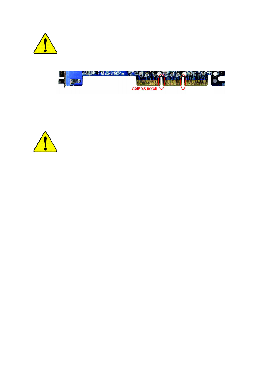
When you installing AGP card, please make sure the following
notice is fully understood and practiced. If your AGP card has
"AGP 4X/8X (1.5V) notch"(show below), please make sure your
AGP card is AGP 4X/8X (1.5V).
AGP 4X/8X notch
Caution: AGP 2X card is not supported by Intel® 845(GE/PE) / 845(E/
G) / 850(E) / E7205 / 865(G/PE/PL/P) / 875P / 848P. You might
experiencesystem unable to boot up normally. Please insert an AGP
4X/8X card.
Example 1: Diamond Vipper V770 golden finger is compatible with 2X/4X
mode AGP slot. It can be switched between AGP 2X(3.3V) or 4X(1.5V)
mode by adjusting the jumper. The factory default for this card is
2X(3.3V). The GA-8I865P(-G) (or any AGP 4X/8X only) motherboards
might not function properly, if you install this card without switching the
jumper to 4X(1.5V) mode in it.
Example 2: Some ATi Rage 128 Pro graphics cards made by "Power Color",
the graphics card manufacturer & some SiS 305 cards, their golden finger
is compatible with 2X(3.3V)/4X(1.5V) mode AGP slot, but they support 2X
(3.3V) only. The GA-8I865P(-G) (or any AGP 4X/8X only) motherboards
might not function properly, If you install this card in it.
Note: Although Gigabyte's AG32S(G) graphics card is based on ATi Rage
128 Pro chip, the design of AG32S(G) is compliance with AGP 4X(1.5V)
specification. Therefore, AG32S(G) will work fine with Intel® 845(GE/PE) /
845(E/G) / 850(E) / E7205 / 865(G/PE/PL/P) / 875P / 848P based
motherboards.
Page 2
M The author assumes no responsibility for any errors
or omissions that may appear in this document nor
does the author make a commitment to update the
information contained herein.
M Third-party brands and names are the property of
their respective owners.
M Please do not remove any labels on motherboard, this
may void the warranty of this motherboard.
M Due to rapid change in technology, some of the
specifications might be out of date before publication
of this booklet.
Page 3
Mother Board
GA-8I865P -G/GA-8I865P
Jun. 04, 2004
Page 4

DECLARATION OF CONFORMITY
Per FCC Part 2 Section 2.1077(a)
Responsible Party Name:
Add ress:
Phone/Fax No:
hereby declares that the product
Produ ct Name:
Model Nu mber:
Conforms to the following specifications:
FCC Part 15, Subpart B, Section 15.107(a) and Section 15.109
(a),Class B Digital D evice
Supplementary Information:
This device complies with part 15 of the FCC Rules. Operation is
subject to the following two conditions: (1) This device may not
cause harmful and (2) this device must accept any inference received,
including that may cause undes ired operation.
Representative Person’s Name:
Signature:
G.B.T. INC. (U .S.A.)
17358 Railroad Street
City of Indu stry, CA 91748
(818) 854-9338/ (818) 854-9339
Motherboard
GA-8I865P-G/GA-8I865P
ERIC LU
Eric Lu
Date:
Jun. 04, 2004
Page 5

GA-8I865P(-G)
P4 Titan Series Motherboard
USER'S MANUAL
Pentium®4 Processor Motherboard
Rev. 1001
12ME-8I865PG-1001
Page 6

Table of Content
English
Warning ..............................................................................................4
Chapter 1 Introduction .........................................................................5
Chapter 2 Hardware Installation Process ............................................ 11
Chapter 3 BIOS Setup ....................................................................... 31
Features Summary .......................................................................................... 5
GA-8I865P(-G) Motherboard Layout .............................................................. 7
Block Diagram .................................................................................................. 8
Step 1: Install the Central Processing Unit (CPU) ....................................... 12
Step 1-1: CPU Installation ........................................................................................... 12
Step 1-2 : CPU Cooling Fan Installation ...................................................................... 13
Step 2: Install memory modules ................................................................... 14
Step 3: Install expansion cards ..................................................................... 17
Step 4: Install I/O Peripherals Cables .......................................................... 18
Step 4-1: I/O Back Panel Introduction ..........................................................................18
Step 4-2: Connectors & Jumper Setting Introduction ....................................................20
The Main Menu (For example: BIOS Ver. : E3) ........................................... 32
Standard CMOS Features ............................................................................. 34
Advanced BIOS Features.............................................................................. 37
Integrated Peripherals .................................................................................. 38
Power Management Setup ............................................................................ 42
- 2 -GA-8I865P(-G) Motherboard
Page 7

PnP/PCI Configurations ................................................................................. 44
PC Health Status ........................................................................................... 45
Frequency/Voltage Control ............................................................................ 46
Load Fail-Safe Defaults ................................................................................. 49
Load Optimized Defaults ............................................................................... 49
Set Supervisor/User Password ..................................................................... 50
Save & Exit Setup .......................................................................................... 51
Exit Without Saving ...................................................................................... 51
Chapter 4 Technical Reference .......................................................... 53
Flash BIOS Method Introduction ................................................................... 53
2- / 4- / 6- / 8- Channel Audio Function Introduction .................................... 64
Jack-Sensing and UAJ Introduction ............................................................. 70
Xpress Recovery Introduction ....................................................................... 72
Chapter 5 Appendix ..........................................................................75
English
- 3 -
Table of Content
Page 8

Warning
English
Computer motherboards and expansion cards contain very delicate Integrated Circuit (IC) chips. To
protect them against damage from static electricity, you should follow some precautions whenever you
work on your computer.
Installing the motherboard to the chassis…
are no slots to attach the spacers, do not become alarmed you can still attach the spacers to the
mounting holes. Just cut the bottom portion of the spacers (the spacer may be a little hard to cut off, so
be careful of your hands). In this way you can still attach the motherboard to the base without worrying
about short circuits. Sometimes you may need to use the plastic springs to isolate the screw from the
motherboard PCB surface, because the circuit wire may be near by the hole. Be careful, don't let the
screw contact any printed circuit write or parts on the PCB that are near the fixing hole, otherwise it may
damage the board or cause board malfunctioning.
1. Unplug your computer when working on the inside.
2. Use a grounded wrist strap before handling computer components. If you do not have
one, touch both of your hands to a safely grounded object or to a metal object, such as
the power supply case.
3. Hold components by the edges and try not touch the IC chips, leads or connectors, or
other components.
4. Place components on a grounded antistatic pad or on the bag that came with the
components whenever the components are separated from the system.
5. Ensure that the ATX power supply is switched off before you plug in or remove the ATX
power connector on the motherboard.
If the motherboard has mounting holes, but they don't line up with the holes on the base and there
- 4 -GA-8I865P(-G) Motherboard
Page 9

Chapter 1 Introduction
Features Summary
CPU — Socket 478 for Intel® Pentium® 4 (Northwood, Prescott)
with HT Technology
— Intel® Pentium® 4 400/533/800
— 2nd cache depends on CPU
Chipset — North Bridge: Intel® 865P
— South Bridge: Intel® ICH5
Memory — 4 184-pin DDR DIMM sockets
— Supports Dual channel DDR400
— Supports 128MB/256MB/512MB/1GB unbuffered DRAM
— Supports up to 4GB DRAM (Max)
Slots — 1 AGP slot supports 8X/4X(1.5V) mode
— 5 PCI slots
On-Board IDE — 2 IDE bus master (UDMA33/ATA66/ATA100) IDE ports for up
to 4 ATAPI devices
— Can connect up to 4 IDE devices
On-Board Floppy — 1 Floppy port supports 2 FDD with 360K, 720K,1.2M, 1.44M
and 2.88M bytes
On-Board Peripherals — 1 Parallel port supports Normal/EPP/ECP mode
— 2 Serial ports (COMA & COMB)
— 8 USB 2.0/1.1 ports (4 x Rear, 4 x Front by cable)
— 1 IrDA connector for IR/CIR
— 1 Front Audio connector
— 1 PS/2 keyboard
— 1 PS/2 mouse
(Note 1)
MHz FSB
(Note 2)
/DDR333/DDR266 DIMM
(Note 3)
English
to be continued......
Due to chipset (Intel 865P) architecture limitation, a FSB 533 Pentium 4 processor will support
DDR333 and DDR266 mem ory module. A FSB 400 Pentium 4 processor will only support DDR
266 mem ory m odule.
(Note 1)An FSB800 CPU can be supported through overclocking in BIOS.
(Note 2)When FSB800 is selected as CPU frequency, mem ory will automatically adjust to DDR400.
(Note 3)Due to standard PC architecture, a certain amount of mem ory is reserved for system
usage and the refore the actual m emory size is less than the s tated am ount.
For example, 4 GB of mem ory size will instead be shown as 3.xxGB m emory during
system startup.
Introduction- 5 -
Page 10

On-Board LAN (*
On-Board Sound — ALC850 CODEC (UAJ)
English
Serial ATA — 2 Serial ATA connectors (SATA0/SATA1)
Hardware Monitor — CPU/System Fan Revolution detect
I/O Control — IT8712
PS/2 Connector — PS/2 Keyboard interface and PS/2 Mouse interface
BIOS — Licensed AWARD BIOS
Additional Features — Supports EasyTune
Overclocking — Over Voltage (DDR/AGP/CPU) by BIOS
Form Factor — ATX size form factor; 30.5cm x 23.0cm
)
— Build in Marvell 8001 Chipset (10/100/1000 Mbit)
— 1 RJ45 port
— Supports Jack Sensing function
— Supports 2 / 4 / 6 / 8 channel audio
— Supports Line In / Line Out / MIC connection
— Surround Back Speaker (use of Surround-Kit to select)
— SPDIF In / Out
— CD In / Game connector
— Controlled by ICH5
— CPU/System Fan Fail Warning
— CPU Overheat Warning
— System Voltage Detect
— Supports Q-Flash
— Supports @BIOS
— Over Clock (DDR/AGP/CPU/PCI) by BIOS
(*) Only for GA-8I865P-G.
- 6 -GA-8I865P(-G) Motherboard
Page 11

GA-8I865P(-G) Motherboard Layout
KB_MS
English
R_USB
COMA
COMB
USB
MIC_IN
F_AUDIO
GAME
LPT
LINE_OUT
CODEC
)
*
(
LAN
LINE_IN
IT8712
CD_IN
Marv ell
8 0 0 1
SUR_CEN
ATX_12V
(*)
CI
IR_C IR
P4 Titan
SPDIF_IO
SOC KET4 78
Intel® 8 65P
PCI1
PCI2
PCI3
PCI4
PCI5
BIOS
Hyper Threading
GA-8I865P(-G)
DDR1
AGP
BAT
CPU_FAN
DDR2
DDR3
ICH5
CLR_C MOS
F_U SB1
ATX
DDR4
INFO_LIN K
IDE2
SATA 1
SATA 0
SYS_FAN
F_PANEL
F_U SB2
FDD
IDE1
PWR_L ED
(*) Only for GA-8I865P-G.
Introduction- 7 -
Page 12

Block Diagram
English
PCICLK
(33M Hz)
AGPCLK
(66M Hz)
5 PCI
AGP 8X/4X
)
RJ45 (*
Marvell 8001(*
AC97 Link
AC97
CODEC
MIC
LINE-IN
LINE-OUT
)
(2.0/1.1)
Pentium 4
Socket 478
CPU
Intel 865P
ICH5
8 USB
Ports
CPUCLK+/- (100/133/200MHz)
System Bus
400/533/800MHz
266/333/400MHz
HCLK+/- (100/133/200MHz)
48 MHz
LPC BUS
24 MHz
ATA33/66/100
IDE Channels
Serial ATA
Channels
ZCLK (66MHz)
66MHz
33 MHz
14.318 MHz
IT8712
33 MHz
DDR
BIOS
Game Port
Floppy
LPT Port
PS/2
KB/Mouse
COM
Ports
(*) Only for GA-8I865P-G.
- 8 -GA-8I865P(-G) Motherboard
Page 13

English
Introduction- 9 -
Page 14

English
- 10 -GA-8I865P(-G) Motherboard
Page 15

Chapter 2 Hardware Installation Process
To set up your computer, you must complete the following steps:
Step 1- Install the Central Processing Unit (CPU)
Step 2- Install memory modules
Step 3- Install expansion cards
Step 4- Install I/O Peripherals Cables
English
Step 4
Step 3
Step 4
Step 1
Step 2
Step 4
Congratulations you have accomplished the hardware installation!
Turn on the power supply or connect the power cable to the power outlet. Continue with the BIOS/
software installation.
- 11 - Hardware Installation Process
Page 16

Step 1: Install the Central Processing Unit (CPU)
English
Step 1-1: CPU Installation
Before installing the processor, adhere to the following warning:
1. Please m ake sure that the motherboard supports the CPU.
2. Please take note of the one indented corne r of the CPU. If you i nstall the CPU in the wrong
direction, the CPU will not in sert properly. If this occurs, please change the insert direction of
the CPU.
3. Please add an even layer of hea t sink paste between the CPU and heatsink.
4. Please make sure the heatsink is installed on the CPU prior to system use, otherwise
overheating and permanent damage of the CPU may occur.
5. Please set the CPU host fr equency in accordance with the processor specifications. It is not
recomm ended that the system bus frequency be set beyond hardware specifications since
it does not meet the required standards for the peripherals. If you wish to set the frequency
beyond the pr oper specifications, please do so according to your hardware specifications
including the CPU, graphics card, m emory, hard drive, etc.
HT functionality requirement content :
Enabling the functionality of Hyper-Threading Technology for your comp uter system requires all
of the following pl atform compo nents:
- CPU: An In tel® Pentium® 4 Processor with HT Technology
- Chipset: An Intel® Chipset that supports HT Technology
- BIOS: A BIOS that supports HT Technology and has it en abled
- OS: An operation system that has optimizations for HT Technology
Socket
Angling the
r o d t o 6 5
0
Actuation
Lever
1. Ang ling the rod to 65-degree m aybe feel a
kind of tight, and then continue pull the rod
to 90-degre e when "click" noise is heard.
Pin1 indicator
3. CPU Top View
2. Pull the rod to the 90-degree directly.
Pin1 indicator
4. Locate Pin 1 in the socket and look for a (golden)
cut edge on the CPU upper corner. Then insert
the CPU into the sock et.
- 12 -GA-8I865P(-G) Motherboard
Page 17

Step 1-2 : CPU Cooling Fan Installation
Before installing the CPU cooling fan, adhere to the following warning:
1. Please use Intel approved cooling fan.
2. We recommend you to apply the thermal tape to provide better heat conduction
between your CPU and cooling fan.
(The CPU cooling fan might stick to the CPU due to the hardening of the thermal
paste. During this condition if you try to remove the cooling fan, you might pull the
processor out of the CPU socket alone with the cooling fan, and might damage the
processor. To avoid this from happening, we suggest you to either use thermal tape
instead of thermal paste, or remove the cooling fan with extreme caution.)
3. Make sure the CPU fan power cable is plugged in to the CPU fan connector, this
completes the installation.
Please refer to CPU cooling fan user's manual for more detail installation procedure.
English
1. Fasten the cooling fan supporting-base
onto the CPU socket on the
mainboard.
2. Make sure the CPU fan is plugged to
the CPU fan connector, than install
complete.
- 13 - Hardware Installation Process
Page 18

Step 2: Install memory modules
English
The motherboard supports DDR memory modules, whereby BIOS will automatically detect memory
capacity and specifications. Memory modules are designed so that they can be inserted only in
one direction. The memory capacity used can differ with each slot.
Before installing the memory modules, please comply with the following conditions:
1. Please make sure that the memory used is supported by the motherboard. It is
recommended that memory of similar capacity, specifications and brand be used.
2. Before installing or removing memory modules, please make sure that the computer
power is switched off to prevent hardware damage.
3. Memory modules have a foolproof insertion design. A memory module can be installed in only one direction. If you are unable to insert the module, please switch
the direction.
Notch
DDR
GA-8I865P(-G) supports the Dual Channel Technolo gy. After operati ng the Dual Channel Techno logy,
the bandwidth of Memor y Bus will add double up to 6.4GB/s.
GA-8I865P(-G) includes 4 DIM M sockets, and each Channel has two DIM M sockets as following:
Channel A : DIM M 1, DIMM 2
Channel B : DIMM 3, DIM M 4
If you want to operate the Dual Channel Technology, please note the following explanations due to
the limitation of Intel® chipset specifications.
1. Only one DDR memory module is installed: The Dual Channel Technology can't operate
when only one DDR memory module is installed.
- 14 -GA-8I865P(-G) Motherboard
Page 19

2. Two DDR m emory modules are installed (the sam e memory size and type): The Dual
Channel Technology will operate when two me mory modules are inserted individually into
Channel A and B. If you install two mem ory modules in the same channel, the D ual Channel
Techn ology wil l not ope rate.
3. Three DDR mem ory modules are installe d: Please note that The Dual Channel
Technology will not operate when three DDR m emory modules are installed; part of
them will not be detected.
4. Four DDR mem ory modules are installed: If you install four memory modules at the same
time, the D ual Channel Technology will operate only when those m odules have the sam e
mem ory size and type.
We'll strongly recommend our user to slot two DDR memory modules into the DIMMs with the
same color in order for Dual Channel Technology to work.
The following tables include all memory-installed combination types:
(Please note that those types not in the tables will not boot up.)
l Figure 1: D ual Channel Technology (DS: Double Side, SS: Single Side)
DIMM 1 DIMM 2 DIMM 3 DIMM 4
2 me mory modules
4 me mory modules
DS/SS X DS/SS X
X DS/SS X DS/SS
DS/SS DS/SS DS/SS DS/SS
English
l Figure 2: Don't operate Dual Channel Technology (DS: Double Side, SS : Single Side)
DIMM 1 DIMM 2 DIMM 3 DIMM 4
1 me mory module
2 me mory modules
3 me mory modules
DS/SS X X X
X DS/SS X X
X X DS/SS X
X X X DS/SS
DS/SS DS/SS X X
X X DS/SS DS/SS
DS/SS DS/SS DS/SS X
DS/SS DS/SS X DS/SS
DS/SS X DS/SS DS/SS
X DS/SS DS/SS DS/SS
- 15 - Hardware Installation Process
Page 20
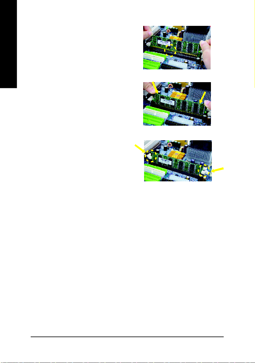
1. The DIMM slot has a notch, so the DIMM
English
2. Insert the DIM M memory module vertically into
3. Close the plastic clip at both edges of the DIM M
DDR Introduction
mem ory m odule can only fit in one direction.
the DIMM slot. Then push it down.
slots to lock the DIMM module.
Reverse the installation steps when you wish
to remove the DIM M module.
Established on the existing SDRAM infrastructure, DDR (Double Data Rate) memory is a high
performance and cost-effective solution that allows easy adoption for memory vendors, OEMs,
and system integrators.
DDR memory is a great evolutionary solution for the PC industry that builds on the existing
SDRAM architecture, yet make the awesome advances in solving the system performance
bottleneck by doubling the memory bandwidth. Nowadays, with the highest bandwidth of 3.2GB/
s of DDR400 memory and complete line of DDR400/333/266/200 memory solutions, DDR memory
is the best choice for building high performance and low latency DRAM subsystem that are
suitable for servers, workstations, and full range of desktop PCs.
- 16 -GA-8I865P(-G) Motherboard
Page 21
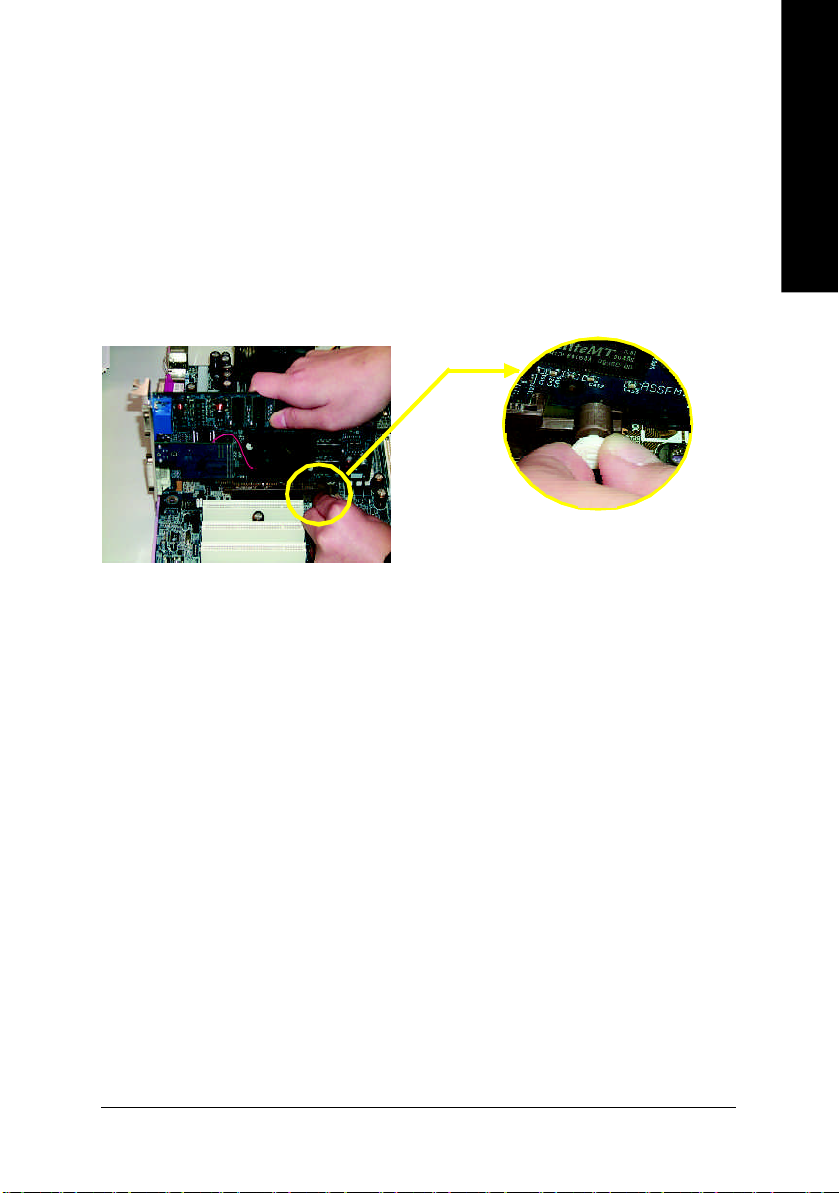
Step 3: Install expansion cards
1. Read the related expansion card's instruction document before install the expansion card into
the computer.
2. Remove your computer’s chassis cover, necessary screws and slot bracket from the computer.
3. Press the expansion card firmly into expansion slot in motherboard.
4. Be sure the metal contacts on the card are indeed seated in the slot.
5. Replace the screw to secure the slot bracket of the expansion card.
6. Replace your computer's chassis cover.
7. Power on the computer, if necessary, setup BIOS utility of expansion card from BIOS.
8. Install related driver from the operating system.
Please carefully pull out the sm all white- drawable bar
at the end of the AGP slot when you try to i nstall/
AGP Card
Uninstall the AGP card. Please align the AGP card to
the onboard AGP slot and press firmly down on the slot
.Make sure your AGP card is locked by the sm all whitedrawable bar.
English
- 17 - Hardware Installation Process
Page 22

Step 4: Install I/O Peripherals Cables
Step 4-1: I/O Back Panel Introduction
English
PS/2 Keyboard and PS/2 Mouse Connector
PS/2 Mouse Connector
(6 pin Female)
PS/2 Keyboard Connector
(6 pin Female)
/ USB / LAN(*) Connector
USB 3
USB 2
(*) Only for GA-8I865P-G.
LAN(*
USB 5
USB 4
This connector supports standard PS/2
keyboard and PS/2 mouse.
Before you connect your device(s) into USB
connector(s), please make sure your
)
device(s) such as USB keyboard,mouse,
scanner, zip, speaker..etc. Have a standard
USB interface. Also make sure your OS
supports USB controller.
If your OS does not support USB controller,
please contact OS vendor for possible patch
or driver upgrade. For more information
please contact your OS or device(s) vendors.
LAN connector is fast Ethernet with 10/100/
1000 Mbps speed.
- 18 -GA-8I865P(-G) Motherboard
Page 23
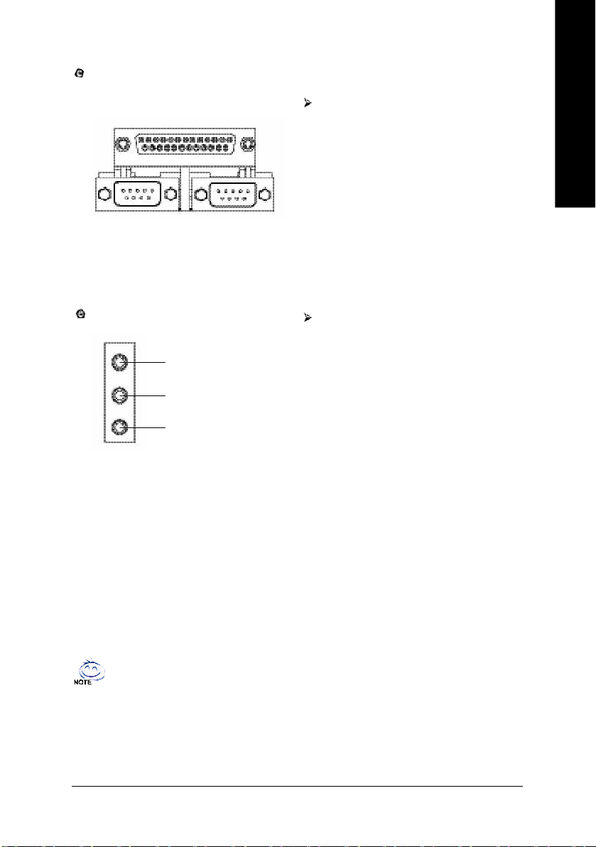
Parallel Port and Serial Ports (COMA/COMB)
Parallel Port
(25 pin Female)
This connector supports 2 standard
COM ports and 1 Parallel port. Device like
printer can be connected to Parallel port;
mouse and modem etc can be connected to
Serial ports.
English
COMA
Serial Port (9 pin Male)
Audio Connectors
Line In
Line Out
MIC In
COMB
After install onboard audio driver, you may
connect speaker to Line Out jack,
microphone to MIC In jack. Devices like
CD-ROM, walkman etc. can be connected
to Line-In jack.
Please note:
You are able to use 2-/4-/6-/8-channel audio
feature by S/W selection.
If you want to enable 8-channel function you
can refer to page 25, and contact your
nearest dealer for optional SUR_CEN cable.
If you want the detail information for 2-/ 4-/ 6-/ 8-channel audio setup
installation, please refer to page 64.
- 19 - Hardware Installation Process
Page 24
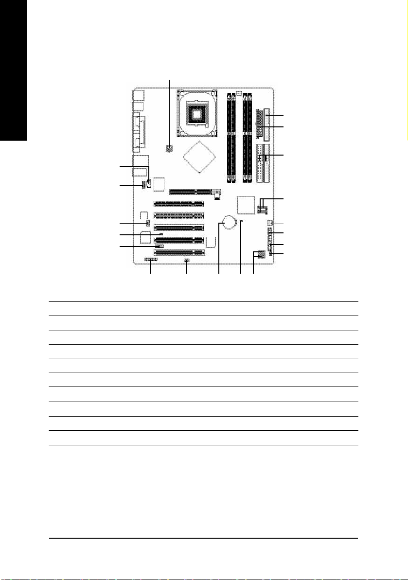
Step 4-2: Connectors & Jumper Setting Introduction
English
1 3
5
2
6
12
10
7
11
18
14
19
16
13
20
15
1) ATX_12V 11) SUR_CEN
2) ATX 12) CD_IN
3) CPU_FAN 13) SPDIF_IO
4) SYS_FAN 14) IR_CIR
5) FDD 15) F_USB1/F_USB2
6) IDE1/IDE2 16) GAME
7) SATA0/SATA1 17) INFO_LINK
8) PWR_LED 18) CI
9) F_PANEL 19) CLR_CMOS
10) F_AUDIO 20) BAT
4
17
9
8
- 20 -GA-8I865P(-G) Motherboard
Page 25
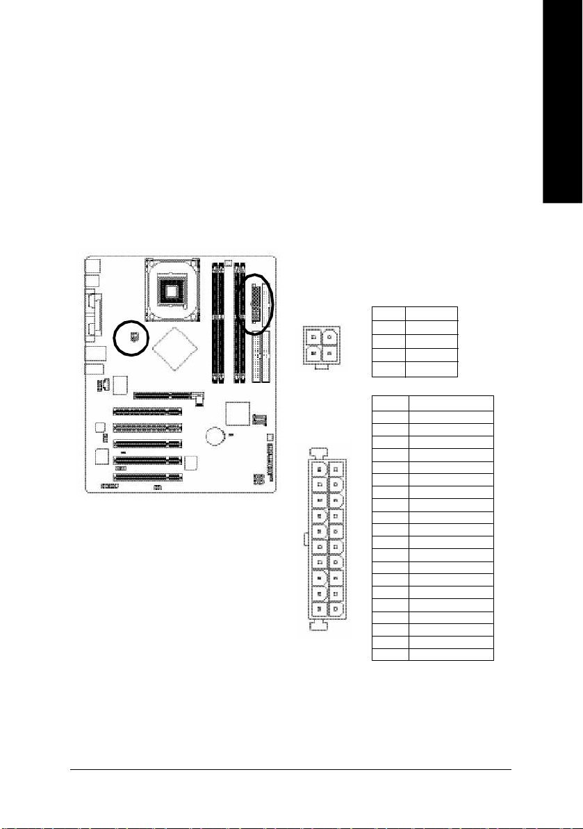
1/2) ATX_12V/ATX (Power Connector)
With the use of the power conn ector, the p ower supply can supply enough stable power to all the
components on the motherboard. Before connecting the power connector, please make sure that all
components and devices are properly installed. Align the power connector with its proper location on
the m otherboard and connect tightly.
The AT X_12V powe r connector mainly supplies po wer to the CPU. If the ATX_12V power
connector is not connected, the system will not start.
Caution!
Please use a power sup ply that is able to handle th e system voltag e requirements. It is
recomm ended that a power supply that can withstand high power consum ption be u sed (300W or
greater). If a power supply is used that does not provide the required power, the result can lead to an
unstable system or a system that is unable to start.
Pin No. Definition
2
4
1
3
11
20
1 GND
2 GND
3 +12V
4 +12V
Pin No. Definition
1 3.3V
2 3.3V
3 GND
4 VCC
5 GND
1
6 VCC
7 GND
8 Power Good
9 5V SB( stand by +5 V)
10 +12V
11 3.3V
12 -12V
13 GND
14 PS_ON(softOn/Off)
15 GND
16 GND
10
17 GND
18 -5V
19 VCC
20 VCC
English
- 21 - Hardware Installation Process
Page 26
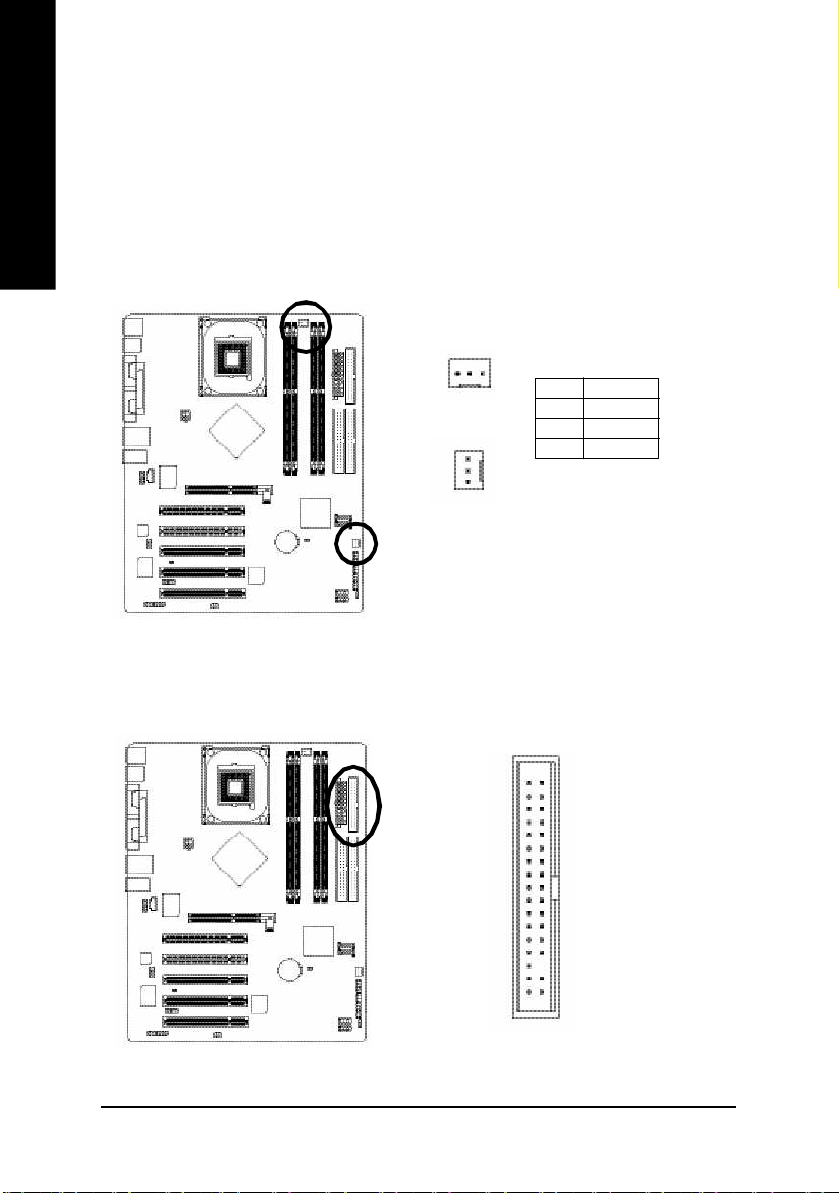
3/4) CPU_FAN / SYS_FAN (Cooler Fan Power Connector)
English
The cooler fan power connector supplies a +12V power voltage via a 3-pin power connector and
possesses a ful-proof connection design.
Most coolers are designed with color-coded power connecto r wires. A red power connector wire
indicates a positive con nection and requ ires a +12V power voltage. The black connector wire is the
ground wi re (GND).
Please remem ber to connect the power to the cooler to prevent system overheating and failure.
Caution!
Please rem ember to connect the power to the CPU fan to pre vent CPU over heating and failure.
1
CPU_FAN
Pin No. Definition
1 GND
2 +12V
3 Sense
1
SYS_FAN
5) FDD (Floppy Connector)
The FDD connector is used to connect the FDD cable while the other end of the cable connects to the
FDD drive. The types of FDD drives supported are: 360KB, 720KB, 1.2MB, 1.44MB and 2.88MB.
Please connect th e red powe r connector wire to the pin1 position.
34
33
2
- 22 -GA-8I865P(-G) Motherboard
1
Page 27

6) IDE1/ IDE2(IDE1/IDE2 Connector)
Each IDE connector can co nnect with one IDE cable to connect the IDE hard drive with the computer.
It is recom mended that the first hard drive be connected to the IDE1 co nnector while the disk drive be
connected to the IDE2 connec tor.
English
7) SATA0/SATA1 (Serial ATA Connector)
You can connect the Serial ATA device to this conn ector.
40
2
IDE2
7
1
39
1
IDE1
Pin No. Definition
1 GND
2 TXP
3 TXN
4 GND
5 RXN
6 RXP
7 GND
- 23 - Hardware Installation Process
Page 28

8) PWR_LED
English
9) F_PANEL (2x10 pins connector)
PWR_LED is connect with the system power indicator to indicate whether the system is on/off. It will blink
when the system enters suspend mode. If you use dual color LED, power LED will turn to another color.
Pin No. Definition
1 MPD+
1
2 MPD3 MPD-
Please connect the power LED, PC peaker, reset switch and power switch etc of your chassis front panel
to the F_PANEL connector according to the pin assignm ent below.
Speaker
Connector
20
Power Swi tch
Mes sa ge LE D/ Po wer /
Sleep LED
MSG-
SPE AK-
SP EAK +
PW-
MSG +
PW+
19
Reset Swi tch
NC
RES +
RES-
HD-
HD+
2
1
IDE H ard Disk
Activ e LED
HD (IDE Hard Disk Ac tive LED) Pin 1: LED anode(+)
(Blue) Pin 2: LED cathode(-)
SPEAK (Speaker Connector) Pin 1: VCC(+)
(Amber) Pin 2- Pin 3: NC
Pin 4: Data(-)
RES (Reset Switch) Open: Normal Operation
(Green) Close: Reset Hardware System
PW (Power Switch) (Red) Open: Normal Operation
Close: Power On/Off
MSG (M essage LED/Power/ Pin 1: LED anode(+)
Sleep LED)(Yellow) Pin 2: LED cathode(-)
NC (Purple) NC
- 24 -GA-8I865P(-G) Motherboard
Page 29

10) F_AUDIO (F_AUDIO Connector)
If you want to use Front Audio connector, you must remove 5-6, 9-10 Jum per. In order to utilize the
front audio header, your chassis must have front audio connector. Also please make sure the pin
assigment on the cable is the sam e as the pin assigm ent on the M B header. To find out if the chassis
you are buying support front audio connector, please contact your dealer.Please note, you can have the
alternati ve of using front audio connector or of using rear audio connector to play sound.
Pin No. Definition
1 MIC
2 GND
1 2
109
3 M IC_BIAS
4 POWER
5 FrontAudio(R)
6 RearAudio(R)
7 Reserved
8 No Pin
9 FrontAudio (L)
10 RearAudio(L)
11) SUR_CEN
Please contact your nearest dealer for optional SUR_CEN cable.
English
Pin No. Definition
1
7 8
2
1 SUR OUTL
2 SUR OUTR
3 GND
4 No Pin
5 CENTER_OUT
6 BASS_OUT
7 AUX_L
8 AUX_R
- 25 - Hardware Installation Process
Page 30

12) CD_IN (CD IN)
English
13) SPDIF_IO (SPDIF In/Out)
Connect CD-ROM or DVD-ROM audio out to the connector.
Pin No. Definition
1
The SPDIF output is capable of providing digital audio to external speakers or com pressed AC3 data to
an external Dolby Digital Decoder. Use this feature only when y our stereo sys tem has digita l input
function. Use SPDIF IN featu re only when your device has dig ital output function.
Be careful with the polarity of the SPDIF_IO connector. Check the pin assignment carefully whil e you
connect the SPDIF cable, incorrect connection between the cable and connector will m ake the
device unable to work or even damage it. For optional SPDIF cable, please contact your local
dealer.
1 CD-L
2 GND
3 GND
4 CD_R
Pin No. Definition
62
5
1
- 26 -GA-8I865P(-G) Motherboard
1 VCC
2 No Pin
3 SPDIF
4 SPDIFI
5 GND
6 GND
Page 31

14) IR_CIR
Make sure the pin 1 on the IR device is aling with pin one the connector. To enable the IR/CIR function
on the board, you are required to purchase an option IR/CIR m odule. For detail information please
contact your autherized Giga-By te distributor. To use IR function on ly, please c onnect IR mo dule to
Pin1 to Pin5.
Be careful with the polarity of the IR/CIR c onnector. Check the pin assignment carefully whil e you
connect the IR/CIR cable, incorrect connection between the cab le and connector will make the device
unable to work or even damag e it. For optional IR/CIR cable, please contact your local dealer.
Pin No. Definition
1 VCC
2 NC
10
6
1
5
3 IRRX
4 GND
5 IRTX
6 NC
7 CIRRX
8 VCC
9 CIRTX
10 NC
15) F_ USB1 / F_USB2(Front USB Connector)
Be careful with the polarity of the front USB connector. Check the pin assignment carefully while
you connect the front USB cable, i ncorrect connection between the cable an d connector will m ake
the device unable to work or even damage it. For option al front USB cable, please contact your
local d ealer.
English
Pin No. Definition
1 Power
2 Power
2
1 9
10
3 USB0 DX-/USB6 DX4 USB1 Dy-/USB7 Dy5 USB0 DX+/USB6 DX+
6 USB1 Dy+/USB7 Dy+
7 GND
8 GND
9 No Pin
10 NC
- 27 - Hardware Installation Process
Page 32

16) GAME (GAME Connector)
This connector supports joystick, MIDI k eyboard and other relate audio devices.
English
17) INFO_LINK
Pin No. Definition
1 VCC
2 GRX1_R
3 GND
4 GPSA2
5 VCC
2
16
1 15
6 GPX2_R
7 GPY2_R
8 M SI_R
9 GPSA1
10 GND
11 GPY1_R
12 VCC
13 GPSB1
14 MSO_R
15 GPSB2
16 No Pin
This connector allows you to connect som e external devic es to provide you extra function.
Pin No. Definition
1 SMBCLK
10
2 1
9
2 VCC
3 SMBDATA
4 GPIO
5 GND
6 GND
7 No Pin
8 NC
9 +12V
10 +12V
- 28 -GA-8I865P(-G) Motherboard
Page 33

18) CI (Chassis Intrusion, Case Open)
This 2 pin connector all ows your system to enable or dis able the "case o pen" item in BIO S if the
system case begin remove.
Pin No. Definition
1
1 Signal
2 GND
19) CLR_CMOS (Clear CMOS)
You m ay clear th e CMOS data to its default values by this jum per. To clear C MOS, temporarily
short 1-2 pi n. Default doesn't incl ude the "Shunter" to pre vent from improper use this jumper.
English
1 Open: Normal
Short: Cl ear CMOS
1
- 29 - Hardware Installation Process
Page 34

20) BAT (Battery)
English
CAUTION
v Danger of explosi on if battery is incorrectly
replaced.
v Replace only with th e same or equivalent
type recom mended by the manufacturer.
v Dispos e of used batteries according to the
manufacturer's instructions.
If yo u want to erase CMOS...
1.Turn OFF the computer and unplug the power
c ord.
2.Remov e the battery, wait for 30 second.
3.Re-install the battery.
4.Plug the power cord and turn ON the com puter.
- 30 -GA-8I865P(-G) Motherboard
Page 35

Chapter 3 BIOS Setup
BIOS (Basic Input and Output System) includes a C MOS SETUP utility which allows user to configure
required settings or to activ ate certain sy stem features.
The CMOS SETUP sav es the configuration in the CMOS SRAM of the motherboard.
When the power is turned off, the battery on the motherboard supplies the necessary power to the C M OS
SRAM.
When the power is turned on, pushing the <Del> button during the BIOS POST (Power-On Self Test) will
take you to the CM OS SETUP screen. You can enter the BIOS setup screen by pressing " Ctrl + F1".
When setting up BIOS for the first time, it is recommended that you save the current BIOS to a disk in the
event that BIOS needs to be reset to its original settings. If you wish to upgrade to a new BIOS, either
Gigabyte's Q-Flash or @BIOS utility can be used.
Q-Flash allows the user to quickly and easily update or backup BIOS without entering the op erating
system.
@BIOS is a Windows-based utility that does not require users to boot to DOS before upgrading BIOS but
directly download and update BIOS from the Internet.
CONTROL KEYS
<á> Move to previous item
<â> Move to next item
<ß> Move to the item in the left hand
<à> Move to the item in the right hand
Enter Select item
<Esc> Main Menu - Quit and not sav e changes into CMOS Status Page Setup Menu and
Option Page Setup M enu - Exit current page and return to Main Menu
<+/PgUp> Increase the numeric value or make changes
<-/PgDn> Decrease the numeric value or make changes
<F1> General help, only for Status Page Setup Menu and Option Page Setup M enu
<F2> Item Help
<F3> Reserved
<F4> Reserved
<F5> Restore the prev ious C MOS value from C MOS, only for Option Page Setup M enu
<F6> Load the file-safe default CM OS value from BIOS default table
<F7> Load the Optimized Defaults
<F8> Q-Flash function
<F9> System Information
<F10> Save all the CM OS changes, only for Main Menu
English
- 31 - BIOS Setup
Page 36

GETTI NG HELP
The on-line description of the highlighted setup function is display ed at the bottom of the screen.
English
Press F1 to pop up a small help window that describes the appro priate keys to use and the possible
selections for the highlighted item. To ex it the Help Window press <Esc>.
The Main Menu (For example: BIOS Ver. : E3)
Once you enter Aw ard BIOS CMOS Setup U tility, the Main Menu will appear on the screen. The Main
Menu allows y ou to select from eight setup functions and two e xit choices. Use arrow keys to select
among the items and press <Enter> to accept or enter the sub-menu.
Main Menu
Status Page S etup Menu / Option Page Setup Menu
CMOS Setup Utility -Copyright (C) 1984 -2004 Award Soft ware
} Standard CM OS Features
} Advanced BI OS Features
} Inte grated Peripherals
} P owe r Managem ent S etup
} P nP/PCI Con figurations
} P C Health Status
} Frequ ency/Voltage Control
ESC: Quit higf: Selec t Item
F8: Q- Flash F10: Save & Exit Setup
Time, Date, Har d Disk Ty pe...
Load Fail-Safe Defa ults
Load Optimized Defa ults
Set Supervisor P assword
Set U ser P ass word
Save & Exit S etup
Exit Without Saving
If yo u can't fi nd the set ting you want, please press "Ctr l+F1" to
search the advanced option widden.
l Standard CMOS Features
This setup page includes all the items in standard compatible BIOS.
l Advanced BI OS Features
This setup page includes all the items of Aw ard special enhanced features.
l Integrated Peripherals
This setup page includes all onboard peripherals.
- 32 -GA-8I865P(-G) Motherboard
Page 37

l Power Management Setup
This setup page includes all the items of Green function features.
l PnP/PCI Configurations
This setup page includes all the configurations of PCI & PnP ISA resources.
l PC Health Status
This setup page is the System auto detect Temperature, voltage, fan, speed.
l Frequency/Voltage C ontrol
This setup page is control CPU 's clock and frequency ratio.
l Load Fail-Safe Defaults
Fail-Safe Defaults indicates the value of the sy stem parameters which the system w ould
be in safe configuration.
l Load Optimized Defaults
Optimized Defaults indicates the value of the sy stem parameters which the system w ould
be in best performance configuration.
l Set Supervis or password
Change, set, or disable passw ord. It allows you to limit access to the sy stem and Setup,
or just to Setup.
l Set User password
Change, set, or disable passw ord. It allows you to limit access to the sy stem.
l Save & Exit S etup
Save CM OS value settings to CMOS and ex it setup.
l Exit Without S aving
Abandon all CMOS v alue changes and ex it setup.
English
- 33 - BIOS Setup
Page 38

Standard CMOS Features
English
CMOS Setup Utility -Copyright (C) 1984 -2004 Award Soft ware
Date (m m:dd:yy ) Fri, May 15 2004
Time (hh:m m :ss) 22:3 1:24
} IDE Channel 0 Master [No ne]
} IDE Channel 0 Slave [None]
} IDE Channel 1 Master [No ne]
} IDE Channel 1 Slave [None]
Drive A [1.44M, 3.5"]
Drive B [None]
Floppy 3 Mode S uport [Disa bled]
Holt On [All, But Keyb oard]
Base Memory 640K
Exte nded Me mory 127M
Total Memory 128M
higf: Move Enter: Select +/-/P U/P D: Value F10: Save ESC: Exit F1: General Help
F5: P revious Values F6: Fail-Save De fault F7: Optimized Defa ults
Standard CMOS Feat ures
Item Help
Menu Level}
Change the day, m onth,
year
<We ek>
Sun. to Sat.
<Month>
Jan. to Dec.
<Day>
1 to 31 (or ma ximum
allowe d in the m onth)
<Ye ar>
1999 to 2098
Date
The date format is <w eek>, <month>, <day>, <year>.
Week The w eek, from Sun to Sat, determin ed by the BIOS and is display only
Month The month, Jan . Through Dec.
Day The day , from 1 to 31 (or the maxi mum allowed in the month)
Year The year, from 1999 through 2098
Time
The ti mes format in <hour> <minute> <se cond>. The time is calculated ba se on the 2 4-hour
military-time clock. For ex ample, 1 p.m. is 13: 00:00.
- 34 -GA-8I865P(-G) Motherboard
Page 39

IDE Channel 0 Master, Slave / IDE Channel 1 Master , S lave
IDE HDD Auto-Detection Press " Enter" to select this option for automatic dev ice detection.
IDE C hannel 0 M aster(Slav e) / IDE Channel 1 Master(Slav e) IDE Dev ice Setup. You can use
one of three methods:
Auto Allow s BIOS to automatically detect IDE devi ces during POST(default)
None Select this if no IDE devices are used and the system will skip the automatic
detection step and all ow for faster system star t up.
Manual User can manually input the cor rect settings
Access Mode Use this to set the acc ess mode for the hard drive . The four options are:
CHS/LBA/Large/Auto(default:Auto)
Hard drive information shoul d be labele d on the outside driv e casing. Enter the appropriate option
based on this information.
Cylinder Number of cyli nders
Head Number of h eads
Precomp Write p recomp
Landing Zone Landing zone
Sector Number of sectors
If a hard disk has not been installed, selec t NONE and press <Enter>.
Drive A / Drive B
The category i dentifies the typ es of floppy disk driv e A or drive B that ha s been installed in the
computer.
None No floppy dri ve installed
360K, 5.25" 5.25 inch PC-ty pe standard driv e; 360K byte capa city.
1.2M, 5.25" 5.25 inch AT-type high- density drive; 1.2M by te capacity
(3.5 inch whe n 3 Mode is Enabled).
720K, 3.5" 3.5 inch doubl e-sided drive; 720K byte capacity
1.44M, 3.5" 3.5 i nch double-sided drive; 1.44M by te capacity.
2.88M, 3.5" 3.5 i nch double-sided drive; 2.88M by te capacity.
English
- 35 - BIOS Setup
Page 40

English
Floppy 3 Mode Support (for J apan Area)
Disabled Normal Floppy Drive. ( Default value)
Driv e A Drive A is 3 mod e Floppy Drive.
Driv e B Drive B is 3 mod e Floppy Drive.
Both Drive A & B ar e 3 mode Floppy Dr ives.
Halt on
The category determines whether the computer wil l stop if an error is detected during pow er up.
NO Errors The sy stem boot will not stop for any error that may be detected and
you wi ll be prompted.
All Errors Whenev er the BIOS detects a non-fatal error the system boot wi ll be
stopped.
All, But Key b oard The sy stem boot will not stop for all errors except a key board e rror.
(Default v a lue)
All, But Diskette The system boot will no t stop for all errors ex cept a disk e rror.
All, But Disk/Key The system boot will not stop for all errors ex cept keyboard and disk
errors.
Memory
The category is display-only w hich is determi ned by POST (Power On Self Tes t) of the BIOS.
Base Memory
The POST of the BIOS wi ll determine the amount of base (or conv entional) memory installed
in the system.
The v alue of the base memory is typically 512 K for sy stems w ith 512K memor y install ed on
the motherboard, o r 640 K for systems w ith 640 K or more memory installed on the mother board.
Extended Memory
The BIOS determines how much extended me mory is present du ring the POST.
This is the am ount of memory located abov e 1MB i n the CPU's memory address map.
- 36 -GA-8I865P(-G) Motherboard
Page 41

Advanced BIOS Features
CMOS Setup Utility -Copyright (C) 1984 -2004 Award Soft ware
u Hard Disk Boot Priority [Press Enter]
First Boot Device [Floppy]
Second Boot Device [Hard Disk]
Third Boot Device [CDR OM]
Password C heck [Setup]
# CPU Hy per-Threading [Enabled]
higf: Move Enter: Select +/-/P U/P D: Value F10: Save ESC: Exit F1: General Help
F5: P revious Values F6: Fail-Save De fault F7: Optimized Defa ults
" # " System will detect automatically and show up when y ou install the Intel® Pentium® 4 processor with
HT Technology.
Hard Disk Boot Priority
Press Enter Selec t Hard Disk Boot Device priority.
First / S econd / Third Boot Device
M This feature allow s y ou to select the boot dev ice prio rity.
Floppy Select your b oot device priori ty by Floppy .
LS120 Select your b oot device priority by L S120.
Hard Disk Select your bo ot device priority by Hard Disk.
CDROM Select your b oot device prior ity by CDROM.
ZIP Select your boot device priority by ZIP.
USB-FDD Select your boot device priority by USB-FDD.
USB-ZIP Select your boot dev ice priority by USB-ZIP.
USB-CDROM Select your boot dev ice priority by USB-CDROM.
USB-HDD Select y our boot device priority by USB-HDD.
LAN Select y our boot device priority by LAN.
Disabled Select y our boot device priority by Disabled.
Password Check
Setup The system will boot but will not a ccess to Setup page if the correct
passw ord is no t entered at the prompt. ( Default v alue)
System The system wil l not boot and w il l not access to Setup page if the correct
passw ord is no t entered at the prompt.
Advanced BI OS Feat ures
Item Help
Menu Level}
Select Hard Disk Boot
Device Prio rity
English
- 37 - BIOS Setup
Page 42

English
Integrated Peripherals
CPU Hyper-Threading
Enabled Enables CPU Hy p er Threading Feature . Please note that this feature is
only w orking for opera ting system with m ulti processors m ode supported.
(Default v a lue)
Disabled Disables CPU Hy per Threa ding.
CMOS Setup Utility -Copyright (C) 1984 -2004 Award Soft ware
On-Chip Prim ary PCI IDE [Enabled]
On-Chip Secondary PCI IDE [Enabled]
On-Chip SATA [Auto]
x SATA P ort0 C onfigure as SATA Port0
SATA P ort1 Configur e as SATA P ort1
USB Controller [Enabled]
USB 2.0 Controller [Enabled]
USB K ey board Su pport [Disa bled]
USB Mouse Support [Disa bled]
AC97 Audio [Auto]
O n b o a rd H / W L A N
Onboar d Serial P ort 1 [3F8/IRQ4]
Onboar d Serial P ort 2 [2F8/IRQ3]
UART Mode Se lect [Nor m al]
x UR2 Duplex Mode Half
Onboar d P arallel Port [378/IRQ7]
Parallel P ort Mode [SPP ]
x ECP Mode Use DMA 3
Game P ort Address [201]
higf: Move Enter: Select +/-/P U/P D: Value F10: Save ESC: Exit F1: General Help
F5: P revious Values F6: Fail-Save De fault F7: Optimized Defa ults
Midi Port Add ress [Disa bled]
x Midi Port IRQ 10
CIR Port Add ress [Disa bled]
x CIR Port IRQ 11
(*)
CMOS Setup Utility -Copyright (C) 1984 -2004 Award Soft ware
Inte grated Periphe rals
[Enabled]
Inte grated Periphe rals
Item Help
Menu Level}
If a hard disk
contr oller ca rd is
used, set at Disabled
[Enabled]
Enable on-chip IDE
Port
[Disa bled]
Disable on-chip IDE
Port
Item Help
Menu Level}
higf: Move Enter: Select +/-/P U/P D: Value F10: Save ESC: Exit F1: General Help
F5: P revious Values F6: Fail-Save De fault F7: Optimized Defa ults
(*) Only for GA-8I865P-G.
- 38 -GA-8I865P(-G) Motherboard
Page 43

On-Chip Primary PCI I DE
Enabled Enable onboar d 1st channel IDE port. (Default v alue)
Disabled Disable onboard 1st cha nnel IDE port.
On-Chip Secondary P CI IDE
Enabled Enable onboar d 2nd cha nnel IDE port. (Default v alue)
Disabled Disable onboard 2nd channel IDE port.
On-chip SATAA
Disabled Disable SATA control ler.
Auto When ther e is no dev ice to be plugged in IDE 1 or IDE2, SATA controller
will remap to IDE controller. ( Default v alue)
Manual Set SATA Mode manua lly.
SATA Port0 Configure as
IDE Pri. Ma ster Remap SATA Port 0 to IDE Pri. Master.
IDE Pri . Slave Remap SATA Port 0 to IDE Pri. Slav e.
IDE Sec. Ma ster Remap SATA Port 0 to IDE Sec. Ma ster.
IDE Sec . Slav e Remap SATA Port 0 to IDE Sec. Slav e.
SATA Port0 SATA controller se t to SATA port0. As this mode, it s upport by WinXP or
later OS only. (Default v alue)
SATA Port1 SATA controller se t to SATA port1. As this mode, it s upport by WinXP or
later OS only.
SATA Port1 Configure as
The values depen d on SATA Port0.
USB Controller
Enabled Enable USB Con troller. (Default value)
Disabled Disable USB Controller.
USB 2.0 Controller
Disable this function if you are n ot using onboard U SB 2.0 feature.
Enabled Enable USB 2. 0 Controller. (Default v alue)
Disabled Disable USB 2.0 Contro ller.
USB Keyboard S upport
Enabled Enable USB Key board Support.
Disabled Disable USB Keyboard Su pport. (Default v alue)
English
- 39 - BIOS Setup
Page 44

English
USB Mouse S upport
Enabled Enabl e USB Mouse Support.
Disabled Disable USB M ouse Sup port. (Default v alue)
AC97 Audio
Auto Auto detect AC'97 audio function. (Default value)
Disabled Disable AC'97 a udio function.
Onboard H/W LAN (*
Enabled Enabl e Onboard H/W LAN function. (Default v alue)
Disabled Disable this fun ction.
)
Onboard Serial Port 1
Auto BIOS will autom atically s etup the port 1 add ress.
3F8/IRQ4 Enable onboard Serial port 1 and address is 3F8. ( Default v alue)
2F8/IRQ3 Enable onboard Serial port 1 and address is 2F8.
3E8/IRQ4 Enable onboard Serial port 1 and address is 3E8.
2E8/IRQ3 Enable onboard Serial port 1 and address is 2E8.
Disabled Disable onboard Serial port 1.
Onboard Serial Port 2
Auto BIOS will autom atically s etup the port 2 add ress.
3F8/IRQ4 Enable onboard Serial port 2 and address is 3F8.
2F8/IRQ3 Enable onboard Serial port 2 and address is 2F8. ( Default v alue)
3E8/IRQ4 Enable onboard Serial port 2 and address is 3E8.
2E8/IRQ3 Enable onboard Serial port 2 and address is 2E8.
Disabled Disable onboard Serial port 2.
UART Mod e S elect
This item allo ws you to determine which In fra Red(IR) function of Onboard I/O chip.
ASKIR Set onboard I/O chip UART to ASKIR Mode.
IrDA Set onboard I/O chip UAR T to IrDA Mode.
Normal Set onboard I/O chip UAR T to Normal Mode. ( Default Value)
UR2 Duplex Mode
This function w ill av ailable when "UART Mode Select" doesn't set at Normal.
Half IR Function Duplex Half. (Default v alue)
Full IR F unction Duplex F ull.
(*) Only for GA-8I865P-G.
- 40 -GA-8I865P(-G) Motherboard
Page 45

Onboard Parallel port
This feature allows y ou to select from a giv en set of parameters if the parallel port uses the onboard
I/O control ler.
Disabled Disable onboa rd LPT port.
378/IRQ7 Enabl e onboard LPT port and address is 378/IRQ7. (Default v alue)
278/IRQ5 Enabl e onboard LPT port and addre ss is 278/IRQ5.
3BC/IRQ7 Enable onboard LPT port and address is 3BC/IRQ7.
Parallel Port Mode
This feature allow s y ou to conne ct with a n advanc ed printer via the port mode it supports.
SPP Using Parallel port as Standard Parallel Port. ( Default v alue)
EPP Using Parallel port as Enhanced Parallel Port.
ECP Using Parallel port as Ex tended Capabilities Port.
ECP+EPP Using Parallel port as ECP & EPP mode.
ECP Mode Use DMA
This feature allows y ou to select Direct Memory Access (DMA) channel if the ECP mode s elected.
This function w ill av ailable when "Parallel Port Mode" set at ECP or ECP+EPP.
3 Set ECP Mode Use DMA to 3. (Default v alue)
1 Set ECP Mode Use DMA to 1.
Game Port Address
201 Set G ame Port Address to 201. (Default v alue)
209 Set G ame Port Address to 209.
Disabled Disable this fun ction.
Midi Port Address
300 Set M idi Port Address to 300.
330 Set M idi Port Address to 330.
Disabled Disable this fu nction. (Default v alue)
Midi Port IRQ
5 Set Midi Port IRQ to 5.
10 Set Midi Port IRQ to 10. (Default v alue)
CIR Port Address
310 Set C IR Port A ddress to 310.
320 Set C IR Port A ddress to 320.
Disabled Disable this function. (Default v alue)
CIR Port I RQ
5 Set CIR Port IRQ to 5.
111 Set CIR Port IR Q to 11. (Default v alue)
English
- 41 - BIOS Setup
Page 46

Power Management Setup
English
CMOS Setup Utility -Copyright (C) 1984 -2004 Award Soft ware
ACPI Suspend Type [S1(P OS)]
Power LED in S1 state [Blinking]
Off by P ower button [Instant-off]
PME Event Wake Up [Enabled]
ModemRingOn/Wake OnLan [Enab led]
Resume by Alarm [Disa bled]
x Date ( of Month) Alarm Ever yday
x Time (hh:m m:ss) Alarm 0 : 0 : 0
Power On By Mouse [Disabled]
Power On By Key board [Disabled]
x KB Power ON P assword Enter
AC Back Func tion [Soft-Off]
higf: Move Enter: Select +/-/P U/P D: Value F10: Save ESC: Exit F1: General Help
F5: P revious Values F6: Fail-Save De fault F7: Optimized Defa ults
Power Managem ent Setup
Item Help
Menu Level}
[S1]
Set suspend ty pe to
Power On Su spend under
ACPI OS
[S3]
Set suspend ty pe to
Suspe nd to RAM under
ACPI OS
ACPI Susp end Type
S1(POS) Set A CPI suspend ty pe to S1/POS(P ower On Suspend). (Default v alue)
S3(STR) Set A CPI suspend ty pe to S3/STR(S uspend To RAM).
Power LED in S1 state
Blinking In standby mode(S1), pow er LED w il l blink. (Default v alue)
Dual/OFF In standby mode (S1):
a. If use single color LED, pow er LED w ill turn off.
b. If use dual color LED, power LED will turn to another c olor.
Off by Power button
Instan t-off Press power button then Pow er off i nstantly. (Default v alue)
Delay 4 Sec. Press power button 4 sec. to Po wer off. Enter suspend i f button is pressed
less than 4 sec.
PME Event Wake Up
Disabled Disable this fun ction.
Enabled Enable PME Event Wake up. (Default v alue)
- 42 -GA-8I865P(-G) Motherboard
Page 47

ModemRingOn/WakeOnLAN
An incoming call v ia mo dem can awake the sy stem from any s uspend state or an input signal
comes from the other client serv er on the LAN can awake th e system from any suspend state.
Disabled Disable Modem Ring on/ wake on Lan function.
Enabled Enabl e Modem Ring on/wake on Lan. (Default v alue)
Resume by Alarm
You can set "Re sume by Alarm" item to enabled and ke y in Data/time to p ower on sy stem.
Disabled Disable this function. ( Default v alue)
Enabled Enable alarm function to POWER ON sy stem.
If RTC Alarm Lea d To Power On is Enabled.
Date (of Month ) Alarm : Everyday , 1~31
Time (hh: mm: ss) Alarm : (0~23) : (0~59) : (0~59)
Power On By Mouse
Disabled Disabled this function. (Default value)
Mouse Click Double click on PS/2 m ouse left button to power on the sy stem.
Power On By Keyboard
This feature allow s y ou to set the method for pow ering -on the sy stem.
The option "Pass w ord" allow s you to set up to 5 alphanumeric characters to power-on the system.
The option "Ke yboard 98" allows y ou to use the standard key board 98 to power on the sy stem.
Password Enter from 1 to 5 characters to se t the Key board Pow er On Passw ord.
Disabled Disabled this function. (Default value)
Keyboard 98 If y o ur key board have "P OWER Key" button, y ou can press the key to
power on the sy stem.
KB Power ON Password
When "Power On by Keyboard" set a t Password, you can set the passw ord here.
Enter Input passw ord (fro m 1 to 5 characters) and press Enter to set the Keyboard
Power On pass w ord.
AC BACK Function
Soft-Off When AC-power back to th e system, the system will be in "Off" state.
(Default v a lue)
Full-On When AC-pow er back to the system, the system alw ays in "On" s tate.
Memory When AC-power back to the system, the sy stem will return to the Last state
before AC-power off.
English
- 43 - BIOS Setup
Page 48

PnP/PCI Configurations
English
CMOS Setup Utility -Copyright (C) 1984 -2004 Award Soft ware
PCI 1/P CI 5 IRQ Assignment [Au to]
PCI 2 IRQ Assig nment [Auto]
PCI 3 IRQ Assig nment [Auto]
PCI 4 IRQ Assig nment [Auto]
higf: Move Enter: Select +/-/P U/P D: Value F10: Save ESC: Exit F1: General Help
F5: P revious Values F6: Fail-Save De fault F7: Optimized Defa ults
PnP/ PCI Configurations
Item Help
Menu Level}
PCI 1/PCI 5 IRQ Assignment
Auto Auto assign IRQ to PCI 1/PCI 5. (Default v a lue)
3,4,5,7,9,10,11,12,14,15 Set IRQ 3,4,5,7 ,9,10,11,12,14,15 to PCI 1/P CI 5.
PCI 2 IRQ Assignment
Auto Auto assign IRQ to PCI 2. (Default value)
3,4,5,7,9,10,11,12,14,15 Set IRQ 3,4,5 ,7,9,10,11,12,14,15 to PCI 2.
PCI 3 IRQ Assignment
Auto Auto assign IRQ to PCI 3. (Default value)
3,4,5,7,9,10,11,12,14,15 Set IRQ 3,4,5 ,7,9,10,11,12,14,15 to PCI 3.
PCI 4 IRQ Assignment
Auto Auto assign IRQ to PCI 4. (Default value)
3,4,5,7,9,10,11,12,14,15 Set IRQ 3,4,5 ,7,9,10,11,12,14,15 to PCI 4.
- 44 -GA-8I865P(-G) Motherboard
Page 49

PC Health Status
CMOS Setup Utility -Copyright (C) 1984 -2004 Award Soft ware
Rese t Case Open Status [Disa bled]
Case O pened Yes
Vcore OK
DDR25V OK
+3.3V OK
+5V OK
+12V OK
Curr ent CP U Temperature 33oC
Current CPU FAN Speed 4687 RPM
Curr ent SYST EM FAN Speed 0 RPM
CPU Warning Tempera ture [Disabled]
CPU FAN Fail Wa rning [Disa bled]
SYST EM FAN Fail Warning [Disabled]
higf: Move Enter: Select +/-/P U/P D: Value F10: Save ESC: Exit F1: General Help
F5: P revious Values F6: Fail-Save De fault F7: Optimized Defa ults
Reset Case Open Status
Disabled Don't reset ca se open status. (Default v alue)
Enabled Clear case open status at next boot.
Case Opened
If the case i s closed, "Case O pened" will show "No".
If the case hav e been opened, "Case Opened" w ill show "Yes".
If y o u w ant to reset "C ase Opene d" value, set "Reset Case Open Statu s" to "Enab led" and save
CMOS, your co mputer w ill restart.
Current Voltage (V) V core / DDR25V / +3.3V / +5V / +12V
Detec t system's v oltage status automatically .
Current CPU Temperature
Dete ct CPU Temp. au tomatically..
Current CPU/SYS TEM FAN Speed (RPM)
Detec t CPU/SYSTEM Fan spe ed status automatically .
CPU Warning Temperature
60oC / 140oF Moni tor CPU Temp. at 60oC / 140oF.
70oC / 158oF Moni tor CPU Temp. at 70oC / 158oF.
80oC / 176oF Moni tor CPU Temp. at 80oC / 176oF.
90oC / 194oF Moni tor CPU Temp. at 90oC / 194oF.
Disabled Disable this function. ( Default v alue)
PC Health St atus
Item Help
Menu Level}
[Disa bled]
Don't m onitor
curre nt fan speed
[Enabled]
Clea r case open status
and set to be Disa bled
at next boot
English
- 45 - BIOS Setup
Page 50

English
Frequency/Voltage Control
CPU FAN Fa il W arning
Disabled Fan Warning Fun ction Disable. (Default va lue)
Enabled Fan Warning Function En able.
SYSTEM FAN Fail W arning
Disabled Fan Warning Fun ction Disable. (Default va lue)
Enabled Fan Warning Function En able.
CMOS Setup Utility -Copyright (C) 1984 -2004 Award Soft ware
CPU Clock Ratio [15X]
CPU Host Cl ock Control [Disabled]
x CPU Host Frequency (Mhz) 200
x AGP/P CI/SRC Fixed 66/33/100
Memory Frequency For [Auto]
Memory Frequency (Mhz) 400
AGP/P CI/SRC Frequency (Mhz) 66/33 /100
DIMM OverVol tage Control [Nor mal]
AGP OverVoltage Con trol [Normal]
CPU Voltage Control [Nor mal]
Norm al CP U Vcore 1.5500V
higf: Move Enter: Select +/-/P U/P D: Value F10: Save ESC: Exit F1: General Help
F5: P revious Values F6: Fail-Save De fault F7: Optimized Defa ults
Frequency/Voltage Con trol
Item Help
Menu Level}
CPU Clock Ratio
This setup op tion will automati cally assign by CPU detection.
For Willamette CPU: 8X~23X default: 14X
For C-Steppin g P4: 8X,10X~24X default: 15X
For Northw ood CPU: 12X~2 4X default: 16X
The option w il l display "Locked" and read only if the CPU ratio is not changeable.
CPU Host Clock Control
Please note that if y our system is ov erclocked and cannot restart, please w ait 20secs . for
automatic sy stem restart or clear the CMOS setup data and perform a safe restart.
Disabled Disable CPU Host Clock Control. (Default v alue)
Enabled Enable CPU Host Clock Control.
- 46 -GA-8I865P(-G) Motherboard
Page 51

CPU Host Frequency (Mhz)
This item w ill be available w hen "CPU Host Clock Control" is set to Ena bled.
100MHz ~ 35 5MHz Set CPU Host Clock fr om 100MHz to 355MHz.
If y o u use FSB 400 Pentium 4 processor, p lease set "CPU Clock" to 10 0MHz.If you use F SB533
Pentium 4 processor, please set "CPU Clock" to 133MHz. If y ou use FSB800 Pentium 4
processor, please set "CPU Clock" to 200MHz.
Incorrect using it may c ause your sy stem broken. For power End-User use only !
AGP/PCI/S RC Fixed
This item w ill be available w hen "CPU Host Clock Control" is set to Ena bled.
Serial ATA device is v ery sensitive to SRC clo ck. SRC over clock may make Serial ATA dev ice
function can't w ork prop erly.
Adjust AGP/PCI/SRC cloc k asy chrohous with CPU.
Memory Frequency For
for FSB(Front Si de Bus) frequency =400MHz,
2.66 Memory Frequen cy = Host clock X 2.66.
Auto Set Memory frequency by DRAM SP D data. (Default v alue)
for FSB(Front Side Bus) frequency =53 3MHz,
2.0 Memory Frequen cy = Host clock X 2.0.
2.5 Memory Frequen cy = Host clock X 2.5.
Auto Set Memory frequency by DRAM SP D data. (Default v alue)
for FSB(Front Si de Bus) frequency =800MHz,
2.0 Memory Frequen cy = Host clock X 2.0.
1.6 Memory Frequen cy = Host clock X 1.6.
1.33 Memory Frequen cy = Host clock X 1.33.
Auto Set Memory frequency by DRAM SP D data. (Default v alue)
Memory Frequency (Mhz)
The v alues dep end on CPU Host Frequency( Mhz).
AGP/PCI /S RC Frequency (Mhz)
The v alues depe nd on AGP/PCI/SRC Fixed.
English
- 47 - BIOS Setup
Page 52

English
DIMM OverVol tage Control
Normal Set DIMM OverVo ltage Control to Normal. (Default va lue)
+0.1V Set DIMM Ov erV oltage Control to +0.1V.
+0.2V Set DIMM Ov erV oltage Control to +0.2V.
+0.3V Set DIMM Ov erV oltage Control to +0.3V.
Increase DRAM v oltage ma y get stable for Ov er_Clock. But it may damage to DRAM m odule
when enable this feature.
AGP OverVolt age Control
Normal Set A GP OverVoltage Control to Normal. (Default v a lue)
+0.1V Set AGP OverVo ltage Control to +0.1V.
+0.2V Set AGP OverVo ltage Control to +0.2V.
+0.3V Set AGP OverVo ltage Control to +0.3V.
Increase AGP vo ltage may get stabl e for Over_Clock. But it may damage to AGP Card w hen
enable this feature.
CPU Voltage Control
Supports adjus table CPU Vcore from 0.8375V to 1.7600V. (Default value: N ormal)
Normal CPU Vcore
Display y our CPU Vcore Voltage.
- 48 -GA-8I865P(-G) Motherboard
Page 53

Load Fail-Safe Defaults
CMOS Setup Utility -Copyright (C) 1984 -2004 Award Soft ware
} Standard CM OS Features
} Advanced BI OS Features
} Inte grated Peripherals
} P owe r Managem ent S etup
} P nP/PCI Con figurations
} P C Health Status
} Frequ ency/Voltage Control
ESC: Quit higf: Selec t Item
F8: Q- Flash F10: Save & Exit Setup
Load Fail-Safe Defau lts (Y/N)? N
Load Fail-Safe Defa ults
Load Fail-Safe Defa ults
Load Optimized Defa ults
Set Supervisor P assword
Set U ser P ass word
Save & Exit S etup
Exit Without Saving
Fail-Safe defaults contain the m ost appropriate values of the sy stem parameters that allow
minimum system performance.
Load Optimized Defaults
CMOS Setup Utility -Copyright (C) 1984 -2004 Award Soft ware
} Standard CM OS Features
} Advanced BI OS Features
} Inte grated Peripherals
} P owe r Managem ent S etup
} P nP/PCI Con figurations
} P C Health Status
} Frequ ency/Voltage Control
ESC: Quit higf: Selec t Item
F8: Q- Flash F10: Save & Exit Setup
Load Optimized Defau lts (Y/N)? N
Load Optimized Defa ults
Load Fail-Safe Defa ults
Load Optimized Defa ults
Set Supervisor P assword
Set U ser P ass word
Save & Exit S etup
Exit Without Saving
English
Selecting this field loads the fac tory defaults for BIOS and Ch ipset Features which the
syste m automatically detects.
- 49 - BIOS Setup
Page 54

Set Supervisor/User Password
English
When you select this function, the fo llowing message w ill appear at the center of the screen to assist
you in creating a pass w ord.
Type the pas sw ord, up to e ight characters, an d press <Enter >. You w ill be ask ed to confirm the
password . Type the passw ord a gain a nd press <Enter>. You may also press <Esc > to abort the
selection and not enter a passw ord.
To disable pas sw ord, just press <Enter> w h en you are prompted to enter passw ord. A mess age
"PASSWO RD DISABLED" will appear to confirm the password being disabled. Once the pass w ord is
disabled, the sy stem w ill boot and y ou c an enter Setup freely.
The BIOS Setup program a llows you to specify tw o sepa rate passwords:
SUPERVISOR PAS SWORD and a USER PASSWORD. When disabled, anyone may a ccess all BIOS
Setup program function. When enabled, the Superv isor passw ord is requir ed for entering the BIOS
Setup program and h aving full configuration fields, the User passw ord is requ ired to acc ess o nly
basic items.
If y ou select "System" at "Password Check" in Adv ance B IOS Features Me nu, you w ill be prompted
for the password ev ery time the sy stem is rebooted or any time you try to enter Setup Menu.
If y o u select "Setup" at "Passw ord Check" in Adv ance BIOS Features Menu, you will be pro mpted
only w hen y ou try to enter Setup.
CMOS Setup Utility -Copyright (C) 1984 -2004 Award Soft ware
} Standard CM OS Features
} Advanced BI OS Features
} Inte grated Peripherals
} P owe r Managem ent S etup
} P nP/PCI Con figurations
} P C Health Status
} Frequ ency/Voltage Control
ESC: Quit higf: Selec t Item
F8:Q- Flash F10: Save & Exit Setup
Ente r P assword:
Change/Set/Disable P assword
Load Fail-Safe Defa ults
Load Optimized Defa ults
Set Supervisor P assword
Set U ser P ass word
Save & Exit S etup
Exit Without Saving
- 50 -GA-8I865P(-G) Motherboard
Page 55

Save & Exit Setup
CMOS Setup Utility -Copyright (C) 1984 -2004 Award Soft ware
} Standard CM OS Features
} Advanced BI OS Features
} Inte grated Peripherals
} P owe r Managem ent S etup
} P nP/PCI Con figurations
} P C Health Status
} Frequ ency/Voltage Control
ESC: Quit higf: Selec t Item
F8: Q- Flash F10: Save & Exit Setup
Save to CMOS an d EXIT (Y/N)? Y
Save & Exit S etup
Load Fail-Safe Defa ults
Load Optimized Defa ults
Set Supervisor P assword
Set U ser P ass word
Save & Exit S etup
Exit Without Saving
Type "Y" w ill quit the Setup Utility and save the user setup v alue to RTC CMOS.
Type "N" w ill return to Setup Utility.
Exit Without Saving
CMOS Setup Utility -Copyright (C) 1984 -2004 Award Soft ware
} Standard CM OS Features
} Advanced BI OS Features
} Inte grated Peripherals
} P owe r Managem ent S etup
} P nP/PCI Con figurations
} P C Health Status
} Frequ ency/Voltage Control
ESC: Quit higf: Selec t Item
F8: Q- Flash F10: Save & Exit Setup
Quit Without Saving (Y/ N)? N
Abandon all Data
Load Fail-Safe Defa ults
Load Optimized Defa ults
Set Supervisor P assword
Set U ser P ass word
Save & Exit S etup
Exit Without Saving
English
Type "Y" w ill quit the Setup Utility w ithout savin g to RTC CMOS.
Type "N" w ill return to Setup Utility.
- 51 - BIOS Setup
Page 56

English
- 52 -GA-8I865P(-G) Motherboard
Page 57

Revision History
Chapter 4 Technical Reference
Flash BIOS Method Introduction
Method 1 : Q-FlashTM Utility
Q-FlashTM is a BIOS flash utility embedded in Flash ROM.
With this utility, users only have to stay in the BIOS menu
when they want to update BIOS. Q-Flash™ allows users to
flash BIOS without any utility in DOS or Windows. Using
Q-FlashTM indicating no more fooling around with any complicated instructions and operating system since
it is in the BIOS menu.
Please note that because updating BIOS has potential risk, please do it with caution!! We
are sorry that Gigabyte Technology Co., Ltd is not responsible for damages of system
because of incorrect manipulation of updating BIOS to avoid any claims from end-users.
English
Before You Begin:
TM
Before you start updating BIOS with the Q-Flash
1. Download the latest BIOS for your motherboard from Gigabyte's website.
2. Extract the BIOS file downloaded and save the BIOS file (the one with model name.Fxx. For
example, 8KNXPU.Fba) to a floppy disk.
3. Reboot your PC and press Del to enter BIOS menu.
The BIOS upgrading guides below are separated into two parts.
If your motherboard has dual-BIOS, please refer to Part One.
If your motherboard has single-BIOS, please refer to Part Two.
utility, please follow the steps below first.
- 53 -
Tech nical Reference
Page 58

Part One:
Updating BIOS with Q-FlashTM Utility on Dual BIOS Motherboards.
English
suppor ting Q-Flash and Dua l BIOS, the Q-Flash utility and Dual BIOS utility are com bined i n the sam e
scre en. This s ection only d eals with how to use Q-Fl ash utility.
In th e follo wing sect ions, w e take GA-8K NXP Ultr a as the ex ample to g uide y ou how to flash
BIOS fr om an older version to the latest version. For example, from Fa3 to Fba.
The BIOS file is Fa3
before updating
Entering the Q-FlashTM utility:
Step1: To use Q- Flash utility, you m ust press Del in the boot screen to enter BIOS menu.
Som e of Gigabyte m otherboard s are equippe d with dual BIOS. In the BIOS menu of the motherboa rds
Aw ard Modul ar B IOS v 6.00PG, A n Ene rgy Star Ally
Cop yri ght ( C) 198 4-20 03, A wa rd Sof tw are, Inc .
Inte l i87 5P A GPset B IOS for 8K NXP Ultra Fa3
Check Sy stem Heal th OK , VCore = 1 .5250
Main Proce ssor : Intel Penti um(R) 4 1.6GH z (1 33x12)
<CPU ID : 0F2 7 Pat ch ID : 0 027>
Memory Testing : 13107 2K OK
Memory Frequency 266 MHz in Si ngle Channel
Primar y Mast er : F UJIT SU MPE31 70AT ED- 03-08
Primary Slav e : None
Seco ndary Maste r : CRE ATIV EDVD- RM D VD1242E B C1 01
Seconda ry Slave : None
Pres s D EL t o e nter SETU P / D ual BIOS / Q-Fl ash / F9 For Xpress R ecove ry
08/07/2003-i875P-6A79BG03C-00
CMOS Setup Utilit y-Cop yright (C) 1984-2003 Award Soft ware
} Standard CMOS Features
} Advanced BIOS Features
} Integrated Perip herals
} Power Management Setup
} PnP/PCI Configurations
} PC Healt h Stat us
} Frequency/Voltage Control
ESC: Quit higf: Select It em
F8: Dual BIOS/Q-Flash F10: Save & Exit Set up
Enter Dual BIOS/Q-Flash Utilit y (Y/N)? Y
Top Performance
Load Fail-Safe Default s
Load Optimized Defaults
Set Supervisor Password
Set User Password
Save & Exit Setup
Exit Wit hout Saving
Step 2: Press F8 button on your keyboard and then Y button to enter the Dual BIOS/Q -Flash utility.
- 54 -GA-8I865P(-G) Motherboard
Page 59

Exploring the Q-FlashTM / Dual BIOS utility screen
The Q-Fla sh / Dua l BIOS utili ty scre en consi sts of the followin g k ey co mp onents.
Tas k me nu for
Dual BIOS
util ity
Task me nu fo r
Q-FlashTM utility
Boot Fro m.......... ................. .............. M ain Bios
Ma in RO M Type/Siz e............. ............... .SST 49LF003A 5 12 K
Backup ROM Type/Siz e............ .............S ST 49LF003A 5 12 K
Wid e Range Prote ction Di sabl e
Copy Main ROM Data to Backup
Enter : Run hi :Mov e ESC:Rese t F10:Power Off
Dual BIOS U tility
Boot From M ain Bios
Auto Recove ry En abl e
Hal t On Error Di sabl e
Loa d Defau lt Setti ngs
Sav e Settings to CM OS
Q-Fla sh U tility
Load M ain BIOS fro m Floppy
Loa d Ba ckup BIO S from Flopp y
Sav e Ma in BI OS to Fl oppy
Sav e Back up BIOS to Flop py
Dual BIOS utility bar
Q-Fl ashTM utility ti tle
bar
Action bar
Task menu for Dual BIOS utility:
Contains the names of eight tasks and two item showing information about the BIOS ROM type. Blocking
a task and pressin g Enter key on your keyboard to enable execution of the task.
Task menu for Q-Flash utility:
Contains the nam es of four tasks. Blocking a ta sk an d pressin g En ter key on your ke yboard to enable
execution of the task.
Action bar:
Contains the names of four actions needed to operate the Q -Flash/Dual BIOS utility. Pressing the buttons
mentioned on your keyb oards to perform these actions.
English
Using the Q-FlashTM utility:
This section tells you how to update BIOS using the Q-Flash utility. As described in the "Before you begin"
section above, you must prepare a floppy disk having the BIOS file for your m otherboard and insert i t to
your com puter. If you have already put the floppy disk into your system and have entered the Q-Flash
utility, plea se follow the steps below to flash BIOS.
Steps:
1. Press arr ow buttons on your keyboard to move the light bar to "Load Main BIOS from Floppy" item in
the Q-Flash menu and press Enter button.
Later, you will se e a box pop up showing the BIOS files you previous ly download ed to the floppy dis k.
If you want to save the current BIOS for bac kup purpo se, you can begin Step 1 with "Save M ain
BIOS to Flopp y" item .
- 55 -
Tech nical Reference
Page 60

2. M ove to th e BIOS file yo u want to flash and pres s Ente r.
In this exampl e, we o nly download one BIOS f ile to the f loppy disk so o nly one BIOS file,
8KN XPU.Fb a, is listed.
English
Afte r pressing Ente r, you 'll then see the pro gress o f reading the BIOS file from the floppy d isk.
Please confirm agai n you have the correct BIOS file for your m otherboard.
Boot Fro m.......... ................. .............. M ain Bios
Ma in RO M Type/Siz e............. ............... .SST 49LF003A 512 K
Backup ROM Type/Siz e............ .............S ST 49LF003A 512 K
Wid e Range Prote ction Disa ble
8KN XP U.Fba 512K
To tal size : 1 .39M Free size: 911.5 0K
Copy Main ROM Data to Backup
F5 : R efresh DEL : Delete
Enter : Run hi :Mov e ESC:Rese t F10:Power Off
Boot Fro m.......... ................. .............. M ain Bios
Ma in RO M Type/Siz e............. ............... .SST 49LF003A 512 K
Backup ROM Type/Siz e............ .............S ST 49LF003A 512 K
Wid e Range Prote ction Disa ble
Copy Main ROM Data to Backup
Enter : Run hi :Mov e ESC:Rese t F10:Power Off
Readi ng BI OS file from flop py...
>>>>>>>>> >>>............. .........
Don't Tu rn Off Po we r Or R eset S ystem
Dual BIOS U tility
Boot From Main Bios
1 file(s) fou nd
Auto Recove ry En abl e
Hal t On Error Di sabl e
Loa d Defau lt Setti ngs
Sav e Settings to CM OS
Q-Fla sh U tility
Load M ain BIOS fro m Floppy
Loa d Ba ckup BIO S from Flopp y
Sav e Ma in BI OS to Fl oppy
Sav e Back up BIOS to Flop py
Dual BIOS U tility
Boot From Main Bios
Auto Recove ry En abl e
Hal t On Error Di sabl e
Loa d Defau lt Setti ngs
Sav e Settings to CM OS
Q-Fla sh U tility
Load M ain BIOS fro m Floppy
Loa d Ba ckup BIO S from Flopp y
Sav e Ma in BI OS to Fl oppy
Sav e Back up BIOS to Flop py
Do not trun off po wer or rese t your
system at this stage!!
BIOS file in the floppy d isk.
After BIOS file is read, you'll see a confirmation dialog box asking you "Are you sure to update BIOS?"
3. Press Y button on your keyb oard after you are sure to update BIOS.
The n i t will begi n to u pdate BIOS. Th e pro gress of up dating BIOS will be dis playe d.
Pleas e do not ta ke ou t the floppy disk when it begin s flas hing BIOS.
- 56 -GA-8I865P(-G) Motherboard
Page 61

4. Press any key s to return to the Q-Flash menu when the BIOS updating procedu re is comple ted.
Boot Fro m.......... ................. .............. M ain Bios
Ma in RO M Type/Siz e............. ............... .SST 49LF003A 5 12 K
Backup ROM Type/Siz e............ .............S ST 49LF003A 5 12 K
Wid e Range Prote ction Disa ble
Copy Main ROM Data to Backup
Enter : Run hi :Mov e ESC:Rese t F10:Power Off
Dual BIOS U tility
Boot From Main Bios
Auto Recove ry En abl e
Hal t On Error Disa ble
!! C opy BI OS completed - Pas s !!
Loa d Defau lt Setti ngs
Plea se press an y key to contin ue
Sav e Settings to CM OS
Q-Fla sh U tility
Load M ain BIOS fro m Floppy
Loa d Ba ckup BIO S from Flopp y
Sav e Ma in BI OS to Fl oppy
Sav e Back up BIOS to Flop py
You can repeat Step 1 to 4 to flash the backup BIOS , too.
5. Pres s Esc a nd then Y button to exit the Q- Flash u tility. The co mputer will res tart automatically after
you exi t Q -Fla sh.
Boot Fro m.......... ................. .............. M ain Bios
Ma in RO M Type/Siz e............. ............... .SST 49LF003A 5 12 K
Backup ROM Type/Siz e............ .............S ST 49LF003A 5 12 K
Wid e Range Prote ction Disa ble
Copy Main ROM Data to Backup
Enter : Run hi :Mov e ESC:Rese t F10:Power Off
Dual BIOS U tility
Boot From Main Bios
Auto Recove ry E nab le
Hal t On Error Disa ble
Are y ou su re to R ESET ?
Loa d Defau lt Setti ngs
Sav e Settings to CM OS
[Enter ] to continu re or [ Esc] to abort...
Q-Fla sh U tility
Load M ain BIOS fro m Floppy
Loa d Ba ckup BIO S from Flopp y
Sav e Ma in BI OS to Fl oppy
Sav e Back up BIOS to Flop py
English
After system reboots, you may find the BIOS versio n on your boot screen becom es the one you flashed.
Aw ard Modul ar B IOS v 6.00PG, A n Ene rgy Star Ally
Cop yri ght ( C) 198 4-20 03, A wa rd Sof tw are, Inc .
Inte l i87 5P A GPset B IOS for 8K NXP Ultra Fba
The BIOS file bec omes
Fab after updating
Check Sy stem Heal th OK , VCore = 1 .5250
Main Proce ssor : Intel Penti um(R) 4 1.6GH z (1 33x12)
<CPU ID : 0F2 7 Pat ch ID : 0 027>
Memory Testing : 13107 2K OK
Memory Frequency 266 MHz in Si ngle Channel
Primar y Mast er : F UJIT SU MPE31 70AT ED- 03-08
Primary Slav e : None
Seco ndary Maste r : CRE ATIV EDVD- RM D VD1242E B C1 01
Seconda ry Slave : None
Pres s D EL t o e nter SETU P / D ual BIOS / Q-Fl ash / F9 For Xpress R ecove ry
09/23/2003-i875P-6A79BG03C-00
- 57 -
Tech nical Reference
Page 62

6. Press Del to enter BIOS menu after system reboots. When you are in BIOS menu, move to Load
English
Fai l -Saf e Def au lt s item and pres s Ente r to l oad BIOS Fai l-Sa fe Defau lts. Nor ma lly the system
redetects all devic es after BIOS has been upg raded. Ther efore, we highly reco mm end reloa ding the
BIOS defaults after BIOS has been upgrade d.
CMOS Setup Utilit y-Cop yright (C) 1984-2003 Award Soft ware
} Standard CMOS Features
} Adva nced BIOS Features
} Int egrated Perip herals
} Pow er Man ageme nt Setu p
} PnP /P CI Con figura ti ons
} PC Health Status
} Frequency /Volt age Cont rol
ESC: Quit higf: Select It em
F8: Dual BIOS/Q-Flash F10: Save & Exit Set up
Load Fail-Safe Defaults (Y/N)? Y
Top Performance
Load Fail-Safe Default s
Load Optimized Defaults
Set Supervisor Password
Set User Password
Save & Exit Setup
Exit Wit hout Saving
Top Performance
Load Fail-Safe Default s
Load Optimized Defaults
Set Supervisor Password
Set User Password
Save & Exit Setup
Exit Wit hout Saving
Press Enter o n
your keyboa rd
Pres s Y on you r
keyb oard to
load de faults.
7. Select Save & Exit Setup item to save the settings to CMOS and exit the BIOS me nu.
System will reboot after you exit the BIOS m enu. The procedure is completed.
CMOS Setup Utilit y-Cop yright (C) 1984-2003 Award Soft ware
} Standard CMOS Features
} Adva nced BIOS Features
} Int egrated Perip herals
} Pow er Man ageme nt Setu p
} PnP /P CI Con figura ti ons
} PC Health Status
} Frequency /Volt age Cont rol
ESC: Quit higf: Select It em
F8: Dual BIOS/Q-Flash F10: Save & Exit Set up
Save to CMOS and EXIT (Y/N)? Y
Top Performance
Load Fail-Safe Default s
Load Optimized Defaults
Set Supervisor Password
Set User Password
Save & Exit Setup
Exit Wit hout Saving
Press Y on your
keyboa rd to
save and e xit.
- 58 -GA-8I865P(-G) Motherboard
Page 63

Part Two:
Updating BIOS with Q-FlashTM Utility on Single-BIOS Motherboards.
This part guides users of single- BIOS motherboards how to update BIOS using the Q-Fl ash™ utility.
Entering the Q-FlashTM utility:
Step1: To use the Q-Flash utility, you m ust press Del in the boot scre en to enter BIOS me nu.
CMOS Setup Utilit y-Cop yright (C) 1984-2003 Award Soft ware
} Standard CMOS Features
} Advanced BIOS Features
} Integrated Perip herals
} Power Management Setup
} PnP/PCI Configurations
} PC Healt h Stat us
} Frequency/Voltage Control
ESC: Quit higf: Select It em
F8: Q-Flash F10: Save & Exit Set up
Enter Q-Flash Utility (Y/N)? Y
Top Performance
Load Fail-Safe Default s
Load Optimized Defaults
Set Supervisor Password
Set User Password
Save & Exit Setup
Exit Wit hout Saving
Step 2: Press F8 bu tton on your keyb oard and then Y button to enter the Q-Flash utility.
Exploring the Q-FlashTM utility screen
The Q-Fla shBIOS utility scre en cons ists of the foll owing key com pone nts.
English
Ta sk m enu fo r
Q-FlashTM utility
Flash Typ e/Size...... ................ ........ SST 49LF003A 2 56 K
Q-Flash Utility V1 .30
Kee p D MI Data En ab le
U pdate BIOS fr om Flopp y
Sav e BIOS to Floppy
Enter : Run hi :Mov e ESC:Rese t F10:Power Off
Q-FlashTM utility bar
Action bar
Task menu for Q-Flash utility:
Contains the names of three tasks. Blocking a task an d pressing Ente r key on your keyboard to enable
execution of the task.
Action bar:
Contains the names of four actions needed to operate the Q-Flash utility. Pressing the buttons mentioned
on your keyboard s to perform these actions.
- 59 -
Tech nical Reference
Page 64

Using the Q-FlashTM utility:
This section tells you how to update BIOS using the Q-Flash utility. As described in the "Before you begin"
section above, you must prepare a floppy disk having the BIOS file for your m otherboard and insert i t to
your com puter. If you have already put the floppy disk into your system and have entered the Q-Flash
English
utility, plea se follow the steps below to flash BIOS.
Steps:
1. Press arr ow buttons on your keyboard to move the light bar to "Update BIOS from Floppy" item in the
2. M ove to th e BIOS file yo u want to flash and pres s Ente r.
In this exampl e, we o nly download one BIOS f ile to the f loppy disk so o nly one BIOS file,
8GE800. F4, is liste d.
Q-Flash m enu and press Enter button.
Later, you will see a box pop up showing the BIOS files y ou previously downloaded to the floppy disk.
If you want to save the current BIOS for bac kup purpo se, you can begin Step 1 with "Save B IOS
to Flop py" item .
Please confirm agai n you have the correct BIOS file for your m otherboard.
Flash Typ e/Size...... ................ ........ SST 49LF003A 2 56 K
8GE 800. F4 256K
Enter : Run hi :Mov e ESC:Rese t F10:Power Off
To tal size : 1 .39M Free size:1.1 4M
F5 : R efresh DEL : Delete
Flash Typ e/Size...... ................ ........ SST 49LF003A 2 56 K
Readi ng BI OS file from flop py...
>>>>>>>>> >>>............. .........
Enter : Run hi :Mov e ESC:Rese t F10:Power Off
Don't Tu rn Off Po we r Or R eset S ystem
Q-Flash Utility V1 .30
Kee p D MI Data En ab le
U pdate BIOS fr om Flopp y
1 file(s) fou nd
Sav e BIOS to Floppy
Q-Flash Utility V1 .30
Kee p D MI Data En ab le
U pdate BIOS fr om Flopp y
Sav e BIOS to Floppy
BIOS fil e in the floppy disk.
Do not trun off powe r or
res et y our sys tem at this
stage! !
After BIOS file is read, you'll see a confirmation dialog box asking you "Are you sure to update BIOS?"
Pleas e do not ta ke ou t the floppy disk when it begin s flas hing BIOS.
- 60 -GA-8I865P(-G) Motherboard
Page 65

3. Press Y button on your keyb oard after you are sure to update BIOS.
Then it wi ll begin to update BIOS. The progres s of updating BIOS will be shown at the sa me tim e.
Flash Typ e/Size...... ................ ........ SST 49LF003A 2 56 K
Enter : Run hi :Mov e ESC:Rese t F10:Power Off
Don't Tu rn Off Po we r Or R eset S ystem
Q-Flash Utility V1 .30
Kee p D MI Data En ab le
Up dating BIO S N ow...
U pdate BIOS fr om Flopp y
>>>>>>>> >>>>>>.......... ..............
Sav e BIOS to Floppy
The porc ess of updatin g
BIOS
Do no t trun o ff power or
rese t your s ystem at this
stage! !
4. Press any key s to return to the Q-Flash menu when the BIOS updating procedu re is comple ted.
Flash Typ e/Size...... ................ ........ SST 49LF003A 2 56 K
Enter : Run hi :Mov e ESC:Rese t F10:Power Off
Q-Flash Utility V1 .30
Kee p D MI Data En ab le
U pdate BIOS fr om Flopp y
!! C opy BI OS completed - Pas s !!
Sav e BIOS to Floppy
Pleas e press any key to continue.. ........
5. Pres s Esc a nd then Y button to exit the Q- Flash u tility. The co mputer will res tart automatically after
you exi t Q -Fla sh.
Flash Typ e/Size...... ................ ........ SST 49LF003A 2 56 K
Enter : Run hi :Mov e ESC:Rese t F10:Power Off
Q-Flash Utility V1 .30
Kee p D MI Data En ab le
U pdate BIOS fr om Flopp y
Are y ou su re to R ESET ?
Sav e BIOS to Floppy
[Enter ] to continu re or [ Esc] to abort...
English
After system reboots, you may find the BIOS versio n on your boot screen becom es the one you flashed.
Aw ard Modul ar B IOS v 6.00PG, A n Ene rgy Star Ally
Cop yri ght ( C) 198 4-20 03, A wa rd Sof tw are, Inc .
The BIOS file bec omes
Fab after updating
Inte l 845 GE AG PSet BI OS for 8GE80 0 F4
Chec k Syste m Healt h OK
Main Proc essor : Int el Pentium(R) 4 1 .7GHz ( 100x 17.0)
<CPU ID : 0F0 A Pat ch ID : 000 9>
Memory Test ing : 12 2880K O K + 8192K Sh ared Memory
Primar y Mast er : F UJIT SU MPE31 70AT ED- 03-08
Primary Slav e : None
Seco ndary Maste r : CRE ATIV EDVD- RM D VD1242E B C1 01
Seconda ry Slave : None
Pres s DEL to ente r SE TUP / Q -F lash
03/18/2003-I845 GE-6A69YG01C-00
6. Pres s Del to enter BIOS m enu after sys tem re boots a nd "Loa d BIOS Fai l-Safe Defaults". Se e how
to Load B IOS Fai l-Safe Defaul ts, please kindly refer to Step 6 to 7 in Pa rt One.
Congratulation!! You have updated BIOS successfully!!
- 61 -
Tech nical Reference
Page 66

Method 2: @ BIOS Utility
If you don't have DOS boot disk, we recommend that you used Gigabyte @BIOS
flash BIOS.
English
TM
program to
Press here.
1.Click "@BIOS"
(1)
3.Click "P".
Methods and steps:
I. Update BIOS through Internet
a. Click "Internet Update" icon
b. Click "Update New BIOS" icon
c. Select @BIOSTM sever
d. Select the exact model name on your motherboard
e. System will automatically download and update the BIOS.
4.Click here.
(3)
2.Click"Start"-"Programs"-
"GIGABYTE"-"@BIOS"
(2)
5. Please select @BIOS sever site,
then Click "OK".
(4)
- 62 -GA-8I865P(-G) Motherboard
Page 67

II. Update BIOS NOT through Internet:
a. Do not click "Internet Update" icon
b. Click "Update New BIOS"
c. Please select "All Files" in dialog box while opening the old file.
d. Please search for BIOS unzip file, downloading from internet or any other methods (such as:
8I865P-G.F1).
e. Complete update process following the instruction.
III. Save BIOS
In the very beginning, there is "Save Current BIOS" icon shown in dialog box. It means to save the
current BIOS version.
IV. Check out supported motherboard and Flash ROM:
In the very beginning, there is "About this program" icon shown in dialog box. It can help you check
out which kind of motherboard and which brand of Flash ROM are supported.
Note:
a. In method I, if it shows two or more motherboard's model names to be selected, please make
sure your motherboard's model name again. Selecting wrong model name will cause the
system unbooted.
b. In method II, be sure that motherboard's model name in BIOS unzip file are the same as your
motherboard's. Otherwise, your system won't boot.
c. In method I, if the BIOS file you need cannot be found in @BIOSTM server, please go onto
Gigabyte's web site for downloading and updating it according to method II.
d. Please note that any interruption during updating will cause system unbooted
English
- 63 -
Tech nical Reference
Page 68

2- / 4- / 6- / 8- Channel Audio
Function Introduction
English
The installation of windows 98SE/2K/ME/XP is very simple. Please follow next step to install the
function!
Stereo Speakers Connection and Settings:
We recomm end that you use the speaker with amplifier to acqiire the best sound effect if the stereo output
is appli ed.
STEP 1:
Connect the stereo speaker s or earph one to "Line
Out".
STE P 2 :
Following ins tallation of the audio drive r, you find a
icon a Sound Effect icon on the lo wer right hand
taskbar . Click the icon to se lect the function.
Line O ut
STEP 3 :
Click "Speake r Configura tion" then click o n the left
sele ction bar an d sele ct "2C H Spea ker" to com -
plete 2 cha nnel audi o configuration.
- 64 -GA-8I865P(-G) Motherboard
Page 69

4 Channel Analog Audio Output Mode
STEP 1 :
Connect the fron t channels to "Line Out",
the rear channels to "Line In".
STE P 2 :
Following ins tallation of the audio drive r, you find a
icon a Sound Effect icon on the lo wer right hand
taskbar . Click the icon to se lect the function.
STE P 3 :
Click "Speake r Configur ation" and sel ect the "UAJ
Function". Then c lick on the left selection bar a nd
select "4CH Spe aker" to com plete 4 channel au dio
configuration.
English
Line O ut Li ne In
- 65 -
Tech nical Reference
Page 70

Basic 6 Channel Analog Audio Output Mode
Use the back au dio panel to connect the audio out-
put witho ut any addi tional modu le.
English
STEP 1 :
Conne ct the front chan nels to "Line Ou t", the re ar
chan nels to "Li ne In" , a nd the Cen ter/Sub woofer
channels to "M IC In".
Line In
STE P 2 :
Following ins tallation of the audio drive r, you find a
icon a Sound Effect icon on the lo wer right hand
taskbar . Click the icon to se lect the function.
STE P 3 :
Click "Speake r Configur ation" and sel ect the "UAJ
Function". Then c lick on the left selection bar a nd
select "6CH Spe aker" to com plete 6 channel au dio
configuration.
M IC In
Line O ut
- 66 -GA-8I865P(-G) Motherboard
Page 71

8 Channel Audio Setup (using Audio Combo Kit, Optional Device):
(Aud io Co mbo K it offers SPDIF o utput, a n optic al
and co axial c able and a Surroun d-Kit. The
Surround-Ki t offers R/L surround , center/subwoofer
output and rear surrou nd)
STE P 1 :
Secu re the A udio C om bo K it a t the pane l on the
back of the cas e.
STE P 2 :
Connec t th e Surrou nd-Kit to the SUR_CEN connector lo cated o n the mo therboard.
English
ST EP 3 :
Th ere are two methods of 8 chan nel aud io
con figura tion:
M ethod 1:
Co nn ect the fron t ch ann el s to th e "L INE OUT "
port located o n the audio pane l and the rear cha n-
nel s to the S urr oun d-Ki t "RE AR R/L" por t. C on-
nec t the cen ter/ sub woofe r c han nel s to the Sur -
rou nd- Kit " SUB CE NTER " a nd th e R /L cha nnel s
to the Su rr oun d-K it "SU R B ACK " p ort.
- 67 -
Tech nical Reference
Page 72

M ethod 2:
Co nn ect the fron t ch ann el s to th e "L INE OUT "
port located o n the audio pane l and the rear cha n-
English
ne ls to th e "L INE IN" p or t. Co nne ct the cen ter/
sub woofer cha nnel s to the "M IC IN" po rt lo cated
on the aud io panel an d th e R /L chann els to the
Sur rou nd- Kit "SU R B ACK" por t. (T his m etho d
req uir es UAJ fun ction )
STE P 4 :
Following ins tallation of the audio drive r, you find a
icon a Sound Effect icon on the lo wer right hand
taskbar . Click the icon to se lect the function.
STE P 5 :
Click "Spe aker Configu ration" and se lect both the
"UA J Fun ction " and "O nly S urr oun d-Ki t". The n
cl ick on the le ft s el ecti on bar and se lec t "8C H
Speaker" to com plete 8 channel audio configuration.
So un d E ffec t C on fig u ra tio n:
At the sound effect menu, users can adjust
so un d op ti on s etti ng s as des ir ed .
- 68 -GA-8I865P(-G) Motherboard
Page 73

SPDIF Output Device (Optional Device)
A "SPDIF output" device is available on the
motherboard. Cable with rear bracket is provided
and could link to the "SPDIF output" connector (As
picture.) For the further linkage to decoder, rear
bracket provides coaxial cable and Fiber
connecting port.
1. Connect the SPDIF output device to the rear
brac ket of P C, and fix it with sc rew.
2. Connect SPDIF device to the motherboard.
English
3. Connect S PDIF to the SPDIF decoder.
- 69 -
Tech nical Reference
Page 74

Jack-Sensing and UAJ Introduction
Jack-Sensing provides audio connectors error-detection function.
English
Jack-Sensin g includes 2 parts: AUTO a nd M ANUAL. Fol lowing is an example for 2 channe ls (Windows
XP):
Introduction of audio connectors
You may c onn ect CDR OM , Walk m an or other s
audio input device s to Line In jack, speakers , ear-
phon e or o thers o utput devi ces to Li ne O ut j ack,
and m icrop hone to MIC In jac k.
Install M icrosoft DirectX8.1 or later version before to enable Jack-Sensing support for Windows
98/98SE/2000 /ME.
Auto-detecting:
Plea se co nnect the de vices to the right jac ks
as a bove . A wind ow wil l ap pear a s ri ght pic-
ture if you setup the dev ices properl y.
Ple ase n ote that 3D audio fu nctio n wil l onl y
appear when 3D audi o inputs.
- 70 -GA-8I865P(-G) Motherboard
Page 75

If you se t wrong with the conne ctors, the warning
mes sage will c ome ou t as right picture.
Manual setting:
If the devic e pi cture shows d ifferent from what you
set, plea se press " Man ual Sel ection" to set.
English
UAJ Introduction
UAJ ( Univ ersa l Au dio J ack) has a v ery sm art feature : It wil l switch sign al auto ma ticall y when u ser
plugs his audio dev ice to the wrong jack (Line -in/ Line-o ut). That means users do no t need to worry the
aud io dev ice sho uld be p lug in Line-i n or L ine -out jac k, the devi ce will work perfectly a fter UAJ i s
activ ated.
Enable UAJ function:
You ca n cli ck "UAJ Au tom atic" button to e nabl e
UAJ fun ction.
- 71 -
Tech nical Reference
Page 76

Xpress Recovery Introduction
What is Xpress Recovery ?
English
working properly, the user can restore the drive to its original state.
How to use the Xpress Recovery
1. Boot from CD-ROM (BMP Mode)
Enter the BIOS menu, select "Advanced BIOS Feature" and set to boot from CD-ROM. Insert the
provided driver CD into your CD drive, then save and exit the BIOS menu. Once the computer has
restarted, the phrase "Boot from CD:" will appear at the bottom left-hand corner of the screen. When "Boot
from CD:" appears, press any key to enter Xpress Recovery.
Once you have completed this step, subsequent access to Xpress Recovery can also function by
pressing the F9 key during computer power on.
Xpress Recovery is a utility used to back up and restore an OS partition. If the hard drive is not
1. Supports FAT16, FAT32, and NTFS formats
2. Must be connected to the IDE1 Master
3. Allows installation of only one OS
4. Must be used with an IDE hard disk supporting HPA
5. The first partition must be set as the boot partition. When the boot partition is backed up,
please do not alter its size.
6. Xpress Recovery is recommended when using Ghost to return boot manager to NTFS
format.
.
.
Verifying DMI Pool Data
Boot from CD:
Boot from CD:
Xpress Recovery V1.0 (C) Copy Right 2003. GIGABYT E Tec hnology CO. , Ltd.
1. Exec ute Back up Utility
2. Exec ute Restore Utility
3. Rem ove Backup Im age
4. S et Pa ssword
5. Exi t and R estart
Build 2011
- 72 -GA-8I865P(-G) Motherboard
Page 77

2. Press F9 during powering on the computer. (Text Mode)
Press F9 during powering on the computer .
Award Modular BIOS v6.00 PG, An Energy Star Al ly
Copyright (C) 1984-2002, Award Software, Inc.
Intel 865PE AGPSet BIOS for 8IPE1000MT F1
Check System Health OK
.
.
.
Press DEL to enter SETUP / Q-Flash, F9 For Xpress Recovery
08/16/2002-I845GE-6A69YG01C-00
Xpress Recovery V1.0 (C) Copy Right 2003. GIGABYT E Tec hnology CO. , Ltd.
1. Exec ute Back up Utility
2. Exec ute Restore Utility
3. Rem ove Backup Im age
4. S et Pa ssword
5. Exi t and R estart
English
F9 For Xpress Recovery
1. If you have already entered Xpress Recovery by booting from the CD-ROM, you can
enter Xpress Recovery in the future by pressing the F9 key.
2. System storage capacity as well as drive reading/writing speed will affect backup speed.
3. It is recommended that Xpress Recovery be immediately installed after OS and all
required driver and software installations are complete.
- 73 -
Tech nical Reference
Page 78

1. Execute Backup Utility:
! Press B to Backup your System or Esc to Exit
English
2. Execute Restore Utility:
! This program will recover your system to factory default.
3. Remove Backup Image:
! Remove backup image. Are you sure? (Y/N)
4. Set Password:
! Please input a 4-16 character long password (a-z or 0-9) or press Esc to exit
The backup utility will automatically scan your system and back up data as a backup image in
your hard drive.
Not all systems support access to Xpress Recovery by pressing the F9 key during computer
power on. If this is the case, please use the boot from CD-ROM method to enter Xpress
Recovery.
Press R to restore your system back to factory default or press Esc to exit
Restores backup image to original state.
Remove the backup image.
You can set a password to enter Xpress Recovery to protect your hard disk data. Once this is done,
password input will be required to enter Xpress Recovery during the next as well as subsequent
system restarts. If you wish to remove the need for password entry, please select "Set Password"
and under "New Password/Confirm Password", make sure there is no entry and then press
"Enter" to remove password requirement.
5. Exit and Restart:
Exit and restart your computer.
- 74 -GA-8I865P(-G) Motherboard
Page 79

Revision History
Chapter 5 Appendix
Install Drivers
Pictures below are shown in Windows XP
Insert the driver CD-title that came with your motherboard into your CD-ROM drive, the
driver CD-title will auto start and show the installation guide. If not, please double click
the CD-ROM device icon in "My computer", and execute the setup.exe.
INSTALL CHIPSET DRIVER
This page shows the drivers that need to be installed for the system. Click each item to install the
driver manually or switch to the to install the drivers automatically.
Massage: Some device drivers will restart your
system automatically. After restarting your
system the "Xpress Install" will continue to
install other drivers.
English
The "Xpress Install" uses the"Click and Go" technology to install the drivers automatically. Just
select the drivers you want then click the "GO" button. The will execute the installation
for you by itself.
We recommend that you install all components in the list.
Click "GO".
- 75 -
Appendix
Page 80

English
Item Description
n Intel Chipset Software Installation Utility
n USB Patch for WinXP
n Marvell 10/100/1000 Base LAN Driver (*
n RealTek AC97 Codec Driver
n Intel USB 2.0 Driver
Driver install finished!! you have to reboot
system!!
Tell the operating system how the chipset components will be configured.
This patch driver can help you to resolve the USB device wake up S3 hang up issue in XP.
)
For Marvell 10/100/1000 LAN chip use.
For Intel(R) ICH/ICH2/ICH4/ICH5 AC97 audio.
It is recommended that you use the Microsoft Windows update for the most updated driver.
For USB2.0 driver support under Windows XP operating system, please use Windows Service
Pack. After install Windows Service Pack, it will show a question mark "?" in "Universal Serial Bus
controller" under "Device Manager". Please remove the question mark and restart the system
(System will auto-detect the right USB2.0 driver).
(*) Only for GA-8I865P-G.
- 76 -GA-8I865P(-G) Motherboard
Page 81

SOFTWARE APPLICATION
This page reveals the value-added software developed by Gigabyte and its worldwide partners.
n Gigabyte Windows Utilities Manager(GWUM)
This utility can integrate the Gigabyte's applications in the system tray.
n Gigabyte Management Tool(GMT)
A useful tool which can manage the computer via the network.
n EasyTune4
Powerful utility that integrates the overclocking and hardware monitoring functions.
n DMI Viewer
Windows based utility which is used to browse the DMI/SMBIOS information of the system.
n Face-Wizard
New utility for adding BIOS logo.
n @BIOS
Gigabyte windows flash BIOS utility.
n Acrobat e-Book
Useful utility from Adobe.
n Acrobat Reader
Popular utility from Adobe for reading .PDF file format documents.
n Norton Internet Security(NIS)
Integrated utility which includes anti-virus, ad control, etc
n DirectX 9
Install Microsoft DirectX 9 to enable 3D hardware acceleration that support for operating
system to achieve better 3D performence.
n Marvell VCT Utility (*
Utility for Marvell chips. [VCT(Virtual Cable Tester) Technology for Gigabit Networks]
)
English
(*) Only for GA-8I865P-G.
- 77 -
Appendix
Page 82

SOFTWARE INFORMATION
This page list the contects of softwares and drivers in this CD title.
English
HARDWARE INFORMATION
This page lists all device you have for this motherboard.
CONTACT US
Please see the last page for details.
- 78 -GA-8I865P(-G) Motherboard
Page 83

FAQ
Below is a collection of general asked questions. To check general asked questions based on a
specific motherboard model, please log on to http://tw.giga-byte.com/faq/faq.htm
Question 1: I cannot see some options that were included in previous BIOS after updating BIOS.
Why?
Answer: Some advanced options are hidden in new BIOS version. Please press Ctrl and F1 keys
after entering BIOS menu and you will be able to see these options.
Questions 2: Why is the light of my keyboard/optical mouse still on after computer shuts down?
Answer: In some boards, a small amount of electricity is kept on standby after computer shuts
down and that's why the light is still on.
Question 3: Why cannot I use all functions in EasyTune™ 4?
Answer: The availability of the listed functions in EasyTune™ 4 depends on the MB chipset. If the
chipset doesn't support certain functions in EasyTune™ 4, these functions will be locked automatically and you will not be able to use them.
Question 4: Why do I fail to install RAID and ATA drivers under Win 2000 and XP on boards that
support RAID function after I connect the boot HDD to IDE3 or IDE4 ?
Answer: First of all, you need to save some files in the CD-ROM to a floppy disk before installing
drivers. You also need to go through some rather different steps in the installation process. Therefore,
we suggest that you refer to the installation steps in the RAID manual at our website.
(Please download it at http://tw.giga-byte.com/support/user_pdf/raid_manual.pdf)
English
Question 5: How do I clear CMOS?
Answer: If your board has a Clear CMOS jumper, please refer to the Clear CMOS steps in the
manual. If your board doesn't have such jumper, you can take off the on-board battery to leak
voltage to clear CMOS. Please refer to the steps below:
Steps:
1. Turn off power.
2. Disconnect the power cord from MB.
3. Take out the battery gently and put it aside for about 10 minutes (Or you can use a
metal object to connect the positive and negative pins in the battery holder to make
them short for one minute).
4. Re-insert the battery to the battery holder.
5. Connect power cord to MB again and turn on power.
6. Press Del to enter BIOS and load Fail-Safe Defaults.
7. Save changes and reboot the system.
- 79 -
Appendix
Page 84

Question 6: Why does system seem unstable after updating BIOS?
Answer: Please remember to load Fail-Safe Defaults (Or Load BIOS Defaults) after flashing
BIOS. However, if the system instability still remains, please clear CMOS to solve the problem.
English
Question 7: Why do I still get a weak sound after turning up the speaker to the maximum volume?
Answer: Please make sure the speaker you are using is equipped with an internal amplifier. If
not, please change another speaker with power/amplifier and try again later.
Question 8: How do I disable onboard VGA card in order to add an external VGA card?
Answer: Gigabyte motherboards will auto-detect the external VGA card after it is plugged in, so
you don't need to change any setting manually to disable the onboard VGA.
Question 9: Why cannot I use the IDE 2?
Answer: Please refer to the user manual and check whether you have connected any cable that
is not provided with the motherboard package to the USB Over Current pin in the Front USB
Panel. If the cable is your own cable, please remove it from this pin and do not connect any of your
own cables to it.
Question 10: Sometimes I hear different continuous beeps from computer after system boots up.
What do these beeps usually stand for?
Answer: The beep codes below may help you identify the possible computer problems. However,
they are only for reference purposes. The situations might differ from case to case.
gAMI BIOS Beep Codes
*Computer gives 1 short beep when system boots successfully.
*Except for beep code 8, these codes are always fatal.
1 beep Refresh failure
2 beeps Parity error
3 beeps Base 64K memory failure
4 beeps Timer not operational
5 beeps Processor error
6 beeps 8042 - gate A20 failure
7 beeps Processor exception interrupt error
8 beeps Display memory read/write failure
9 beeps ROM checksum error
10 beeps CMOS shutdown register read/write error
11 beeps Cache memory bad
- 80 -GA-8I865P(-G) Motherboard
Page 85

g AWARD BIOS Beep Codes
1 short: System boots successfully
2 short: CMOS setting error
1 long 1 short: DRAM or M/B error
1 long 2 short: Monitor or display card error
1 long 3 short: Keyboard error
1 long 9 short: BIOS ROM error
Continuous long beeps: DRAM error
Continuous short beeps: Power error
Question 11:For the M/B which have RAID function, how to set in the BIOS in order to bootup
from IDE3, 4 by either RAID or ATA mode?
Answer:Please set in the BIOS as follow:
1. Advanced BIOS features-->(SATA)/RAID/SCSI boot order: "SATA"
2. Advanced BIOS features--> First boot device: "SCSI"
3. Integrated Peripherals--> Onboard H/W ATA/RAID: "enable"
Then it depends on the RAID mode that you need to set "RAID" to RAID mode or "ATA" to
normal ATA mode in the item named RAID controller function.
Question 12:How to set in the BIOS to bootup from the IDE/ SCSI/ RAID card ?
Answer:Please set in the BIOS as follow:
1. Advanced BIOS features-->(SATA)/RAID/SCSI boot order: "SCSI"
2. Advanced BIOS features--> First boot device: "SCSI"
Then it depends on the mode(RAID or ATA) that you need to set in RAID/ SCSI BIOS.
English
- 81 -
Appendix
Page 86

Troubleshooting
English
If you encounter any trouble during boot up, please follow the troubleshooting
procedures .
START
Turn off the power and unplug the AC power cable, then
remove all of the add-on cards and cables from motherboard.
Please make sure motherboard & chassis are not short ?
No
Yes
Failure has been excluded.
Please isolate
the short pin.
Please make sure all jumper settings (such as CPU system bus
speed, frequency ratio, voltage and etc.) are set properly.
Yes
Check if the CPU cooling fan attached to CPU properly. ls
CPU cooling fan power connected to CPU_FAN
properly?
Yes
Check if the memory install properly into the DIMM slot.
Yes
Insert the VGA card. Then plug in ATX power cable and
turn on the system.
A
No
Failure has been excluded.
No
Failure has been excluded.
No
Failure has been excluded.
Make sure the
jumper setting
are correct.
Plug the CPU
cooling fan power
in the CPU fan
connector. Plug in
the AC power
connector.
Insert and push
the memory
module vertically
into the DIMM slot.
- 82 -GA-8I865P(-G) Motherboard
Page 87

A
Is memory LED on and CPU fan running?
Yes
The problem could
be caused by
power supply, CPU,
No
Failure has been excluded.
memory or CPU/
memory socket
itself.
English
Check if there is display.
Yes
Turn off the system. Reboot after keyboard and mouse
have been plugged in.
Check if keyboard is working properly.
Yes
Press <Del> to enter BIOS setup. Choose "Load
Optimized Defaults" and save then exit setup.
Turn off the system and re-connect the IDE cable. Check
if the system can reboot successfully.
Yes
Reinstall Windows OS, and reinstall add-on cards and cables.
Then try to reboot the system.
No
Failure has been excluded.
No
Failure has been excluded.
No
Failure has been excluded.
Perhaps your VGA
card / VGA slot or
monitor is defective.
It is possible that
your keyboard or
keyboard connector
is defective.
The problem was
probably caus ed by
the IDE device /
connector or cab le.
END
If the above procedure unable to solve your problem, please contact with your local retailer or
national distributor for help. Or, you could submit your question to the service mail via Gigabyte
website technical support zone
(http://www.gigabyte.com.tw). The appropriate response will be provided ASAP.
- 83 -
Appendix
Page 88

Technical Support/RMA Sheet
Customer/Country: Company: Phone No.:
English
Contact Person: E-mail Add. :
Model name/Lot Number: PCB revision:
BIOS version: O.S./A.S.:
Hardware Mfs. Model name Size: Driver/Utility:
Configuration
CPU
Memory
Brand
Video Card
Audio Card
HDD
CD-ROM /
DVD-ROM
Modem
Network
AMR / CNR
Keyboard
Mouse
Power supply
Other Device
&
Problem Description:
&
- 84 -GA-8I865P(-G) Motherboard
Page 89

Acronyms
Acronyms Meaning
ACPI Advanced Configuration and Power Interface
APM Advanced Power Management
AGP Accelerated Graphics Port
AMR Audio Modem Riser
ACR Advanced Communications Riser
BIOS Basic Input / Output System
CPU Central Processing Unit
CMOS Complementary Metal Oxide Semiconductor
CRIMM Continuity RIMM
CNR Communication and Networking Riser
DMA Direct Memory Access
DMI Desktop Management Interface
DIMM Dual Inline Memory Module
DRM Dual Retention Mechanism
DRAM Dynamic Random Access Memory
DDR Double Data Rate
ECP Extended Capabilities Port
ESCD Extended System Configuration Data
ECC Error Checking and Correcting
EMC Electromagnetic Compatibility
EPP Enhanced Parallel Port
ESD Electrostatic Discharge
FDD Floppy Disk Device
FSB Front Side Bus
HDD Hard Disk Device
IDE Integrated Dual Channel Enhanced
IRQ Interrupt Request
English
to be continued......
- 85 -
Appendix
Page 90

Acronyms Meaning
IOAPIC Input Output Advanced Programmable Input Controller
ISA Industry Standard Architecture
English
LAN Local Area Network
I/O Input / Output
LBA Logical Block Addressing
LED Light Emitting Diode
MHz Megahertz
MIDI Musical Instrument Digital Interface
MTH Memory Translator Hub
MPT Memory Protocol Translator
NIC Network Interface Card
OS Operating System
OEM Original Equipment Manufacturer
PAC PCI A.G.P. Controller
POST Power-On Self Test
PCI Peripheral Component Interconnect
RIMM Rambus in-line Memory Module
SCI Special Circumstance Instructions
SECC Single Edge Contact Cartridge
SRAM Static Random Access Memory
- 86 -GA-8I865P(-G) Motherboard
Page 91

English
- 87 -
Memo
Page 92

English
- 88 -GA-8I865P(-G) Motherboard
Page 93

English
- 89 -
Memo
Page 94

English
- 90 -GA-8I865P(-G) Motherboard
Page 95

English
- 91 -
Memo
Page 96

CONTACT US
Contact us via the information in this page all over the world.
— Taiwan
English
Gigabyte Technology Co., Ltd.
Address: No.6, Bau Chiang Road, Hsin-Tien, Taipei Hsien,
Taiwan, R.O.C.
Tel: 886 (2) 8912-4888
Fax: 886 (2) 8912-4003
Tech. Support:
http://tw.giga-byte.com/TechSupport/ServiceCenter.htm
Non-Tech. Support (Sales/Marketing issues):
http://ggts.gigabyte.com.tw/nontech.asp
Website: http://www.gigabyte.com.tw
— USA
G.B.T. INC.
Address: 17358 Railroad St, City of Industry, CA 91748.
Tel: 1 (626) 854-9338
Fax: 1 (626) 854-9339
Tech. Support:
http://www.giga-byte.com/TechSupport/ServiceCenter.htm
Non-Tech. Support (Sales/Marketing issues):
http://ggts.gigabyte.com.tw/nontech.asp
Website: http://www.giga-byte.com
— Germany
G.B.T. Technology Trading GmbH
Tel: 49-40-2533040
49-01803-428468 (Tech.)
Fax: 49-40-25492343 (Sales)
49-01803-428329 (Tech.)
Tech. Support:
http://de.giga-byte.com/TechSupport/ServiceCenter.htm
Non-Tech. Support (Sales/Marketing issues):
http://ggts.gigabyte.com.tw/nontech.asp
Website: http://www.gig abyte .de
— Japan
Nippon Giga-Byte Corporation
Website: http://www.gigabyte.co.jp
— U.K
G.B.T. TECH. CO. LTD.
Tel: 44-1908-362700
Fax: 44-1908-362709
Tech. Support:
http://uk.giga-byte.com/TechSupport/ServiceCenter.htm
Non-Tech. Support (Sales/Marketing issues):
http://ggts.gigabyte.com.tw/nontech.asp
Website: http://uk.giga-byte.com
— The Netherlands
Giga-Byte Technology B.V.
Address: Verdunplein 8 5627 SZ, Eindhoven, The Netherlands
Tel: +31 40 290 2088
NL Tech.Support : 0900-GIGABYTE (0900-44422983, 0.2/M)
BE Tech.Support : 0900-84034 ( 0.4/M)
Fax: +31 40 290 2089
Tech. Support:
http://nz.giga-byte.com/TechSupport/ServiceCenter.htm
Non-Tech. Support (Sales/Marketing issues):
http://ggts.gigabyte.com.tw/nontech.asp
Website: http://www.giga-byte.nl
— China
NINGBO G.B.T. Tech. Trading CO., Ltd.
Tech. Support:
http://cn.giga-byte.com/TechSupport/ServiceCenter.htm
Non-Tech. Support (Sales/Marketing issues):
http://ggts.gigabyte.com.tw/nontech.asp
Website: http://www.gigabyte.com.cn
Beijing
Tel: 86-10-82856054, 86-10-82856064, 86-10-82856094
Fax: 86-10-82856575
Chengdu
Tel: 86-28-85236930
Fax: 86-28-85256822
GuangZhou
Tel: 86-20-87586273
Fax: 86-20-87544306
Shanghai
Tel: 86-21-64737410
Fax: 86-21-64453227
Shenyang
Tel: 86-24-23960918, 86-24-23960893
Wuhan
Tel: 86-27-87854385, 86-27-87854802
Fax: 86-27-87854031
Xian
Tel: 86-29-5531943
Fax: 86-29-5539821
- 92 -GA-8I865P(-G) Motherboard
 Loading...