

Gigabyte GA-8I865PE-TW User Manual [ru]
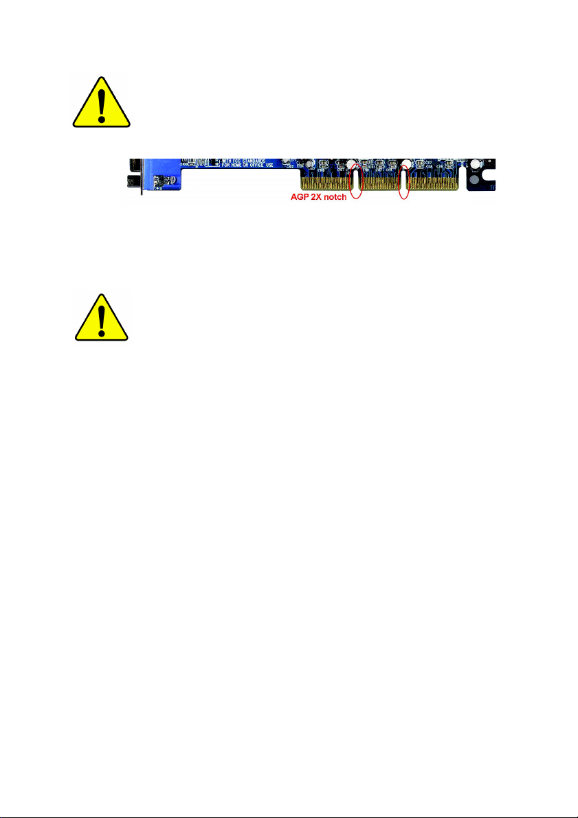
When you are installing AGP card, please make sure the following
notice is fully understood and practiced. If your AGP card has "AGP
4X/8X (1.5V) notch"(show below), please make sure your AGP card
is AGP 4X/8X (1.5V).
AGP 4X/8X notch
Caution: AGP 2X card is not supported by Intel® 845(GE/PE) / 845(E/
G) / 850(E) / E7205 / 865(G/PE/P) / 875P. You might experience system
unable to boot up normally. Please insert an AGP 4X/8X card.
Example 1: Diamond Vipper V770 golden finger is compatible with 2X/4X
mode AGP slot. It can be switched between AGP 2X(3.3V) or 4X(1.5V)
mode by adjusting the jumper. The factory default for this card is
2X(3.3V). The GA-8I865PE-TW (or any AGP 4X/8X only) motherboards
might not function properly, if you install this card without switching the
jumper to 4X(1.5V) mode in it.
Example 2: Some ATi Rage 128 Pro graphics cards made by "Power Color",
the graphics card manufacturer & some SiS 305 cards, their golden finger
is compatible with 2X(3.3V)/4X(1.5V) mode AGP slot, but they support 2X
(3.3V) only. The GA-8I865PE-TW (or any AGP 4X/8X only) motherboards
might not function properly, If you install this card in it.
Note : Although Gigabyte's AG32S(G) graphics card is based on ATi Rage
128 Pro chip, the design of AG32S(G) is compliance with AGP 4X(1.5V)
specification. Therefore, AG32S(G) will work fine with Intel® 845(GE/PE) /
845(E/G) / 850(E) / E7205 / 865(G/PE/P) / 875P based motherboards.
00
0 The author assumes no responsibility for any errors
00
or omissions that may appear in this document nor
does the author make a commitment to update the
information contained herein.
00
0 Third-party brands and names are the property of
00
their respective owners.
00
0 Please do not remove any labels on motherboard, this
00
may void the warranty of this motherboard.
00
0 Due to rapid change in technology, some of the
00
specifications might be out of date before publication
of this booklet.
Mother Board
GA-8I865PE-TW
May 31, 2004
Motherboard
GA-8I865PE-TW
May 31, 2004

GA-8I865PE-TW
P4 Titan Series Motherboard
USER'S MANUAL
Pentium®4 Processor Motherboard
Rev. 1001
12ME-8I865PETW-1001

Table of Contents
English
Warning ...................................................................................................4
Chapter 1 Introduction ............................................................................ 5
Chapter 2 Hardware Installation Process ...............................................9
Chapter 3 BIOS Setup .........................................................................31
Features Summary ....................................................................................... 5
GA-8I865PE-TW Motherboard Layout ......................................................... 7
Block Diagram .............................................................................................. 8
Step 1: Install the Central Processing Unit (CPU) ...................................... 10
Step 1-1: CPU Installation ................................................................................................ 10
Step 1-2 : CPU Cooling Fan Installation ...........................................................................11
Step 2: Install memory modules ................................................................. 12
Step 3: Install expansion cards .................................................................. 15
Step 4: Install I/O Peripherals Cables ........................................................ 16
Step 4-1: I/O Back Panel Introduction .............................................................................. 16
Step 4-2: Connectors & Jumper Setting Introduction ....................................................... 18
The Main Menu (For example: BIOS Ver. : E3) .......................................... 32
Standard CMOS Features .......................................................................... 34
Advanced BIOS Features ........................................................................... 36
Integrated Peripherals ................................................................................ 37
Power Management Setup ......................................................................... 40
PnP/PCI Configurations ............................................................................. 42
PC Health Status ........................................................................................ 43
Frequency/Voltage Control ......................................................................... 44
- 2 -GA-8I865PE-TW Motherboard

Load Fail-Safe Defaults .............................................................................. 46
Load Optimized Defaults ............................................................................ 46
Set Supervisor/User Password .................................................................. 47
Save & Exit Setup ...................................................................................... 48
Exit Without Saving .................................................................................... 48
Chapter 4 Technical Reference ............................................................49
@BIOSTM Introduction ................................................................................ 49
Flash BIOS Method Introduction ................................................................ 50
2- / 4- / 6- / 8- Channel Audio Function Introduction................................... 61
Jack-Sensing and UAJ Introduction ........................................................... 67
Xpress Recovery Introduction .................................................................... 69
Chapter 5 Appendix..............................................................................73
English
- 3 -
Table of Content

Warning
English
Computer motherboards and expansion cards contain very delicate Integrated Circuit (IC) chips. To
protect them against damage from static electricity, you should follow some precautions whenever you
work on your computer.
Installing the motherboard to the chassis…
are no slots to attach the spacers, do not become alarmed you can still attach the spacers to the
mounting holes. Just cut the bottom portion of the spacers (the spacer may be a little hard to cut off, so
be careful of your hands). In this way you can still attach the motherboard to the base without worrying
about short circuits. Sometimes you may need to use the plastic springs to isolate the screw from the
motherboard PCB surface, because the circuit wire may be near by the hole. Be careful, don't let the
screw contact any printed circuit write or parts on the PCB that are near the fixing hole, otherwise it may
damage the board or cause board malfunctioning.
1. Unplug your computer when working on the inside.
2. Use a grounded wrist strap before handling computer components. If you do not have
one, touch both of your hands to a safely grounded object or to a metal object, such as
the power supply case.
3. Hold components by the edges and try not touch the IC chips, leads or connectors, or
other components.
4. Place components on a grounded antistatic pad or on the bag that came with the
components whenever the components are separated from the system.
5. Ensure that the ATX power supply is switched off before you plug in or remove the ATX
power connector on the motherboard.
If the motherboard has mounting holes, but they don't line up with the holes on the base and there
- 4 -GA-8I865PE-TW Motherboard

Chapter 1 Introduction
Features Summary
English
CPU y Socket 478 for Intel® Pentium® 4 (Northwood, Prescott) with HT Technology
y Intel Pentium
®
4 400/533/800
(Note 1)
MHz FSB
y L2 cache varies with CPU
Chipset y Northbridge: Intel
®
865PE MCH
y Southbridge: Intel® ICH5
Memory y 4 DDR DIMM memory slots (supports up to 4GB memory)
y Supports dual channel DDR400
(Note 3)
/333/266 DIMM
(Note 2)
Slots y 1 AGP slot, supports AGP 8X/4X(1.5V) mode
y 5 PCI slots
On-Board IDE y 2 IDE connection (UDMA 33/ATA 66/ATA 100), allows connection of
4 IDE devices
On-Board Floppy y 1 FDD connection, allows connection of 2 FDD devices
On-Board SATA y 2 Serial ATA connections
On-Board Peripherals y 1 parallel port supporting Normal/EPP/ECP mode
y 2 serial port (COMA, COMB)
y 8 USB 2.0/1.1 ports (rear x 4, front x 4 via cable)
y 1 front audio connector
y 1 IR/CIR connector
y 1 PS/2 keyboard port
y 1 PS/2 mouse port
On-Board LAN y Onboard Realtek 8110S (10/100/1000 Mbit)
y 1 RJ45 port
to be continued...
Due to chipset (Intel 875P/865G/865PE) architecture limitation, a FSB 800 Pentium 4 processor
will support DDR400/DDR333/DDR266 memory module. A FSB 533 Pentium 4 processor will
support DDR333 and DDR266 memory module. A FSB 400 Pentium 4 processor will only support
DDR 266 memory module.
(Note 1) An FSB800 CPU can be supported through overclocking in BIOS.
(Note 2) Due to standard PC architecture, a certain amount of memory is reserved for system usage and
therefore the actual memory size is less than the stated amount. For example, 4 GB of memory
size will instead be shown as 3.xxGB memory during system startup.
(Note 3) When FSB800 is selected as CPU frequency, memory will automatically adjust to DDR400.
Introduction- 5 -

On-Board Sound y ALC850 CODEC (UAJ)
English
I/O Control y IT8712
Hardware Monitor y CPU / System fan speed detection
BIOS y Use of licensed AWARD BIOS
Additional Features y Supports @BIOS
Overclocking y Over Voltage via BIOS (CPU/DDR/AGP)
Form Factor y ATX size form factor, 30.5cm x 23.0cm
y Supports Jack Sensing function
y Supports 2 / 4 / 6 / 8 channel audio
y Supports Line In / Line Out / MIC connection
y Surround Back Speaker (use of Surround-Kit to select)
y SPDIF In / Out
y CD In / Game connector
y CPU / System fan failure warning
y CPU temperature detection
y CPU warning temperature
y System voltage detection
y Supports Q-Flash
y Supports EasyTune
y Over Clock via BIOS (CPU/DDR/AGP/PCI)
- 6 -GA-8I865PE-TW Motherboard
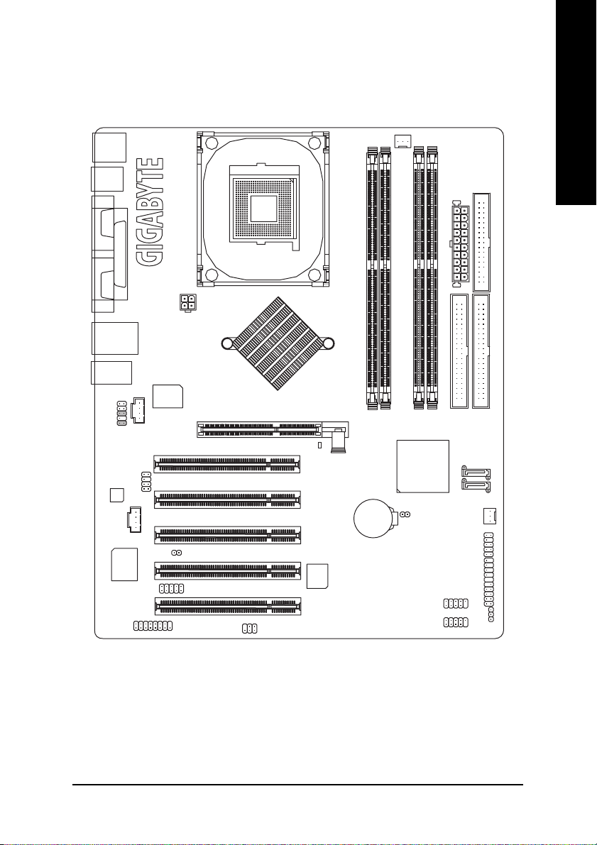
GA-8I865PE-TW Motherboard Layout
KB_MS
English
R_USB
USB
MIC_IN
F_AUDIO
CODEC
COMA
COMB
LINE_OUT
GAME
LPT
LINE_IN
IT8712
LAN
CD_IN
AUX_IN
ATX_12V
Realtek
8110S
SUR_CEN
CI
IR_CIR
SOCKET478
Intel® 865PE
P4 Titan
SPDIF_IO
PCI1
PCI2
PCI3
PCI4
PCI5
2X_DET
BIOS
Hyper Threading
GA-8I865PE-TW
AGP
DDR1
BAT
DDR2
CLR_CMOS
CPU_FAN
DDR3
ICH5
F_USB2
F_USB1
DDR4
INFO_LINK
ATX
IDE2
SATA1
SATA0
SYS_FAN
F_PANEL
FDD
IDE1
PWR_LED
Introduction- 7 -
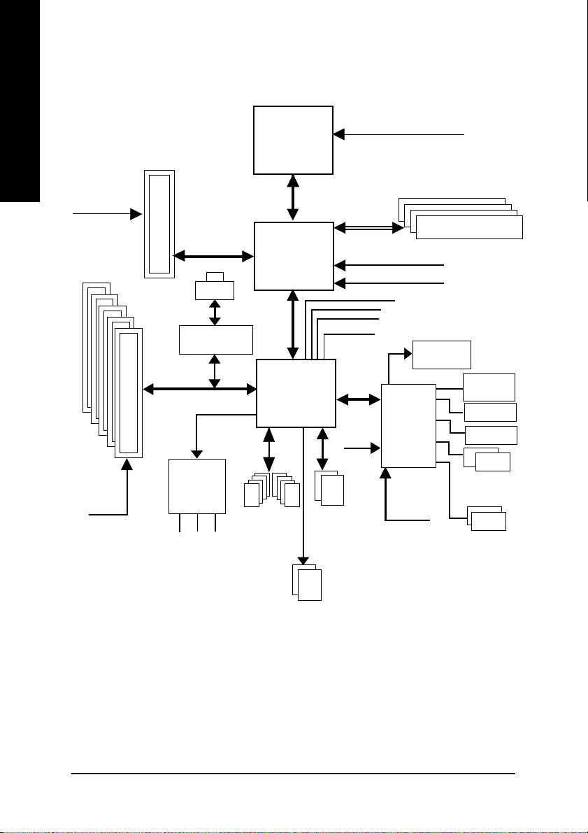
Block Diagram
English
AGPCLK
(66MHz)
5 PCI
PCICLK
(33MHz)
AGP 8X/4X
RJ45
Realtek 8110S
AC97 Link
AC97
CODEC
MIC
LINE-IN
LINE-OUT
Pentium 4
Socket 478
Intel 865PE
8 USB
(2.0/1.1)
Ports
CPU
System Bus
400/533/800MHz
ICH5
ATA33/66/100
IDE Channels
CPUCLK+/- (100/133/200MHz)
266/333/400MHz
ZCLK (66MHz)
HCLK+/- (100/133MHz)
66MHz
33 MHz
48 MHz
LPC BUS
Serial ATA
Channels
14.318 MHz
IT8712
24 MHz
33 MHz
DDR
BIOS
Game Port
Floppy
LPT Port
PS/2
KB/Mouse
COM
Ports
- 8 -GA-8I865PE-TW Motherboard
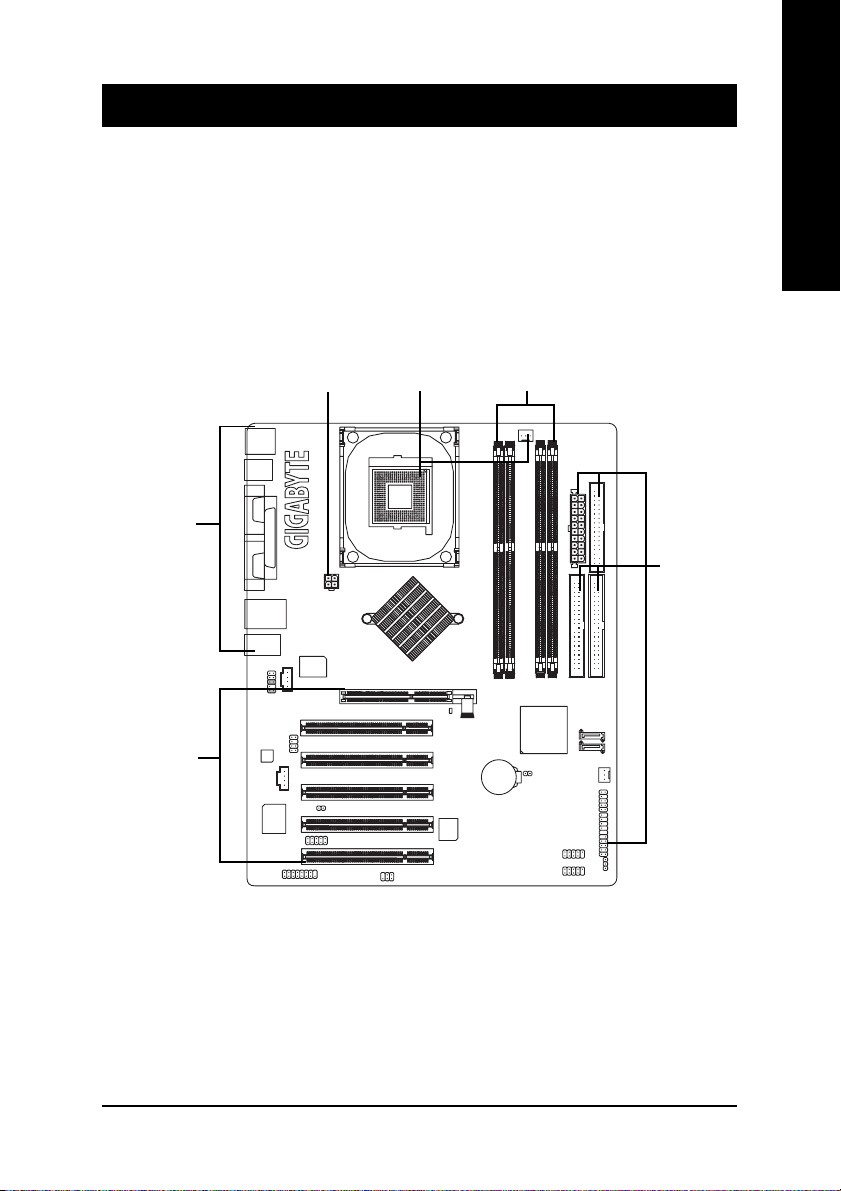
Chapter 2 Hardware Installation Process
To set up your computer, you must complete the following steps:
Step 1- Install the Central Processing Unit (CPU)
Step 2- Install memory modules
Step 3- Install expansion cards
Step 4- Install I/O Peripherals Cables
English
Step 4
Step 3
Step 4
Step 1
Step 2
Step 4
Congratulations you have accomplished the hardware installation!
Turn on the power supply or connect the power cable to the power outlet. Continue with
the BIOS/software installation.
- 9 - Hardware Installation Process
Step 1: Install the Central Processing Unit (CPU)
English
Step 1-1: CPU Installation
Before installing the processor, adhere to the following warning:
1. Please make sure that the motherboard supports the CPU.
2. Please take note of the one indented corner of the CPU. If you install the CPU in the wrong
direction, the CPU will not insert properly. If this occurs, please change the insert direction of
the CPU.
3. Please add an even layer of heat sink paste between the CPU and heatsink.
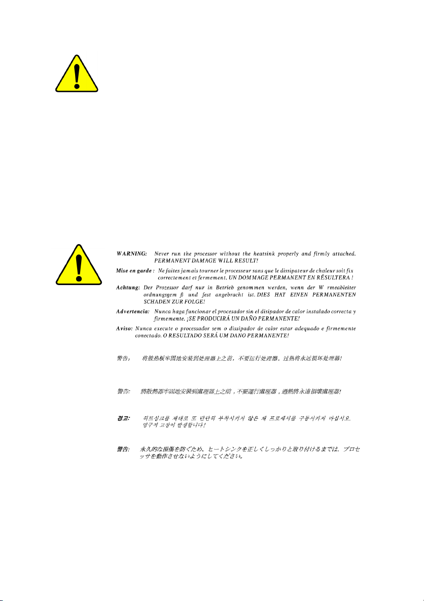
4. Please make sure the heatsink is installed on the CPU prior to system use, otherwise
overheating and permanent damage of the CPU may occur.
5. Please set the CPU host frequency in accordance with the processor specifications. It is not
recommended that the system bus frequency be set beyond hardware specifications since
it does not meet the required standards for the peripherals. If you wish to set the frequency
beyond the proper specifications, please do so according to your hardware specifications
including the CPU, graphics card, memory, hard drive, etc.
HT functionality requirement content :
Enabling the functionality of Hyper-Threading Technology for your computer system requires all
of the following platform components:
- CPU: An Intel® Pentium® 4 Processor with HT Technology
- Chipset: An Intel® Chipset that supports HT Technology
- BIOS: A BIOS that supports HT Technology and has it enabled
- OS: An operation system that has optimizations for HT Technology
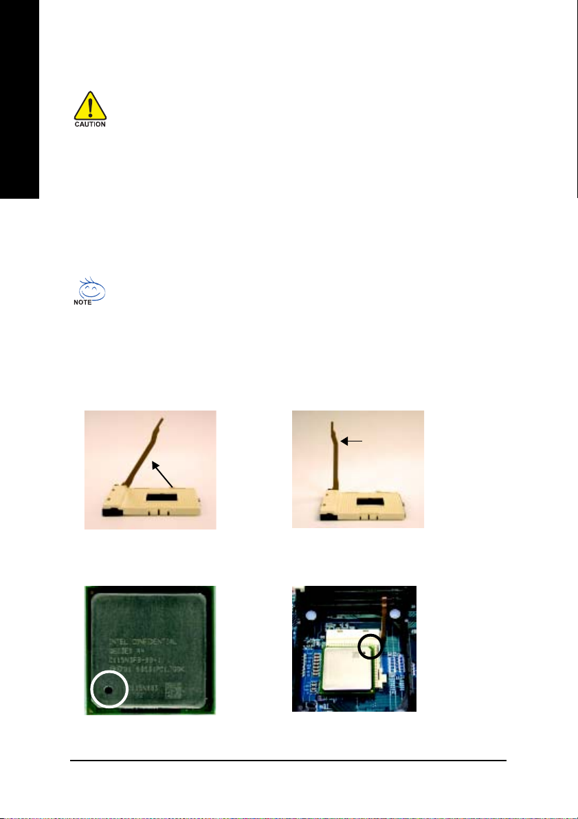
Socket
Angling the
rod to 65
0
Actuation
Lever
1. Angling the rod to 65-degree maybe feel a
kind of tight, and then continue pull the rod
to 90-degree when "click" noise is heard.
Pin1 indicator
3. CPU Top View
2. Pull the rod to the 90-degree directly.
Pin1 indicator
4. Locate Pin 1 in the socket and look for a (golden)
cut edge on the CPU upper corner. Then insert
the CPU into the socket.
- 10 -GA-8I865PE-TW Motherboard
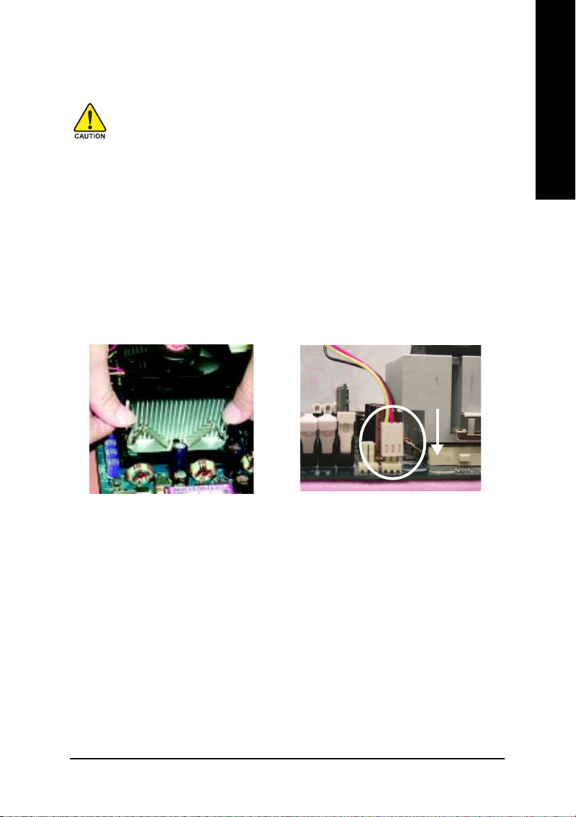
Step 1-2 : CPU Cooling Fan Installation
Before installing the CPU cooling fan, adhere to the following warning:
1. Please use Intel approved cooling fan.
2. We recommend you to apply the thermal tape to provide better heat conduction
between your CPU and cooling fan.
(The CPU cooling fan might stick to the CPU due to the hardening of the thermal
paste. During this condition if you try to remove the cooling fan, you might pull the
processor out of the CPU socket alone with the cooling fan, and might damage the
processor. To avoid this from happening, we suggest you to either use thermal tape
instead of thermal paste, or remove the cooling fan with extreme caution.)
3. Make sure the CPU fan power cable is plugged in to the CPU fan connector, this
completes the installation.
Please refer to CPU cooling fan user's manual for more detail installation procedure.
English
1. Fasten the cooling fan supporting-base
onto the CPU socket on the motherboard.
2. Make sure the CPU fan is plugged to the
CPU fan connector, than install completely.
- 11 - Hardware Installation Process
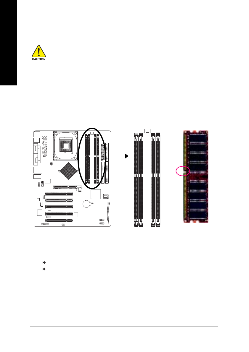
Step 2: Install memory modules
English
The motherboard supports DDR memory modules, whereby BIOS will automatically detect memory
capacity and specifications. Memory modules are designed so that they can be inserted only in
one direction. The memory capacity used can differ with each slot.
Before installing the memory modules, please comply with the following conditions:
1. Please make sure that the memory used is supported by the motherboard. It is
recommended that memory of similar capacity, specifications and brand be used.
2. Before installing or removing memory modules, please make sure that the computer
power is switched off to prevent hardware damage.
3. Memory modules have a foolproof insertion design. A memory module can be installed in only one direction. If you are unable to insert the module, please switch
the direction.
Notch
DDR
GA-8I865PE-TW supports the Dual Channel Technology. After operating the Dual Channel Technology,
the bandwidth of Memory Bus will add double up to 6.4GB/s.
GA-8I865PE-TW includes 4 DIMM sockets, and each Channel has two DIMM sockets as following:
Channel A : DDR 1, DDR 2
Channel B : DDR 3, DDR 4
If you want to operate the Dual Channel Technology, please note the following explanations due to the
limitation of Intel® chipset specifications.
1. Only one DDR memory module is installed: The Dual Channel Technology can't operate when only
one DDR memory module is installed.
2. Two DDR memory modules are installed (the same memory size and type): The Dual Channel
Technology will operate when two memory modules are inserted individually into Channel A and B. If
you install two memory modules in the same channel, the Dual Channel Technology will not operate.
- 12 -GA-8I865PE-TW Motherboard

3. Three DDR memory modules are installed: Please note that The Dual Channel Technology will not
operate when three DDR memory modules are installed; part of them will not be detected.
4. Four DDR memory modules are installed: If you install four memory modules at the same time, the
Dual Channel Technology will operate only when those modules have the same memory size and
type.
We'll strongly recommend our user to slot two DDR memory modules into the DIMMs with the
same color in order for Dual Channel Technology to work.
The following tables include all memory-installed combination types:
(Please note that those types not in the tables will not boot up.)
z Figure 1: Dual Channel Technology (DS: Double Side, SS: Single Side)
DDR 1 DDR 2 DDR 3 DDR 4
2 memory modules
4 memory modules
z Figure 2: Don't operate Dual Channel Technology (DS: Double Side, SS: Single Side)
1 memory module
2 memory modules
3 memory modules
DS/SS X DS/SS X
X DS/SS X DS/SS
DS/SS DS/SS DS/SS DS/SS
DDR 1 DDR 2 DDR 3 DDR 4
DS/SS X X X
X DS/SS X X
X X DS/SS X
X X X DS/SS
DS/SS DS/SS X X
X X DS/SS DS/SS
DS/SS DS/SS DS/SS X
DS/SS DS/SS X DS/SS
DS/SS X DS/SS DS/SS
X DS/SS DS/SS DS/SS
English
- 13 - Hardware Installation Process
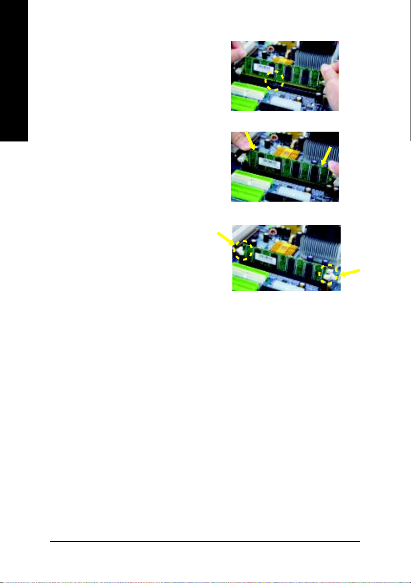
1. The DIMM slot has a notch, so the DIMM
English
2. Insert the DIMM memory module vertically into
3. Close the plastic clip at both edges of the DIMM
DDR Introduction
memory module can only fit in one direction.
the DIMM slot. Then push it down.
slots to lock the DIMM module.
Reverse the installation steps when you wish
to remove the DIMM module.
Established on the existing SDRAM infrastructure, DDR (Double Data Rate) memory is a high
performance and cost-effective solution that allows easy adoption for memory vendors, OEMs,
and system integrators.
DDR memory is a great evolutionary solution for the PC industry that builds on the existing
SDRAM architecture, yet make the awesome advances in solving the system performance
bottleneck by doubling the memory bandwidth. Nowadays, with the highest bandwidth of 3.2GB/
s of DDR400 memory and complete line of DDR400/333/266/200 memory solutions, DDR memory
is the best choice for building high performance and low latency DRAM subsystem that are
suitable for servers, workstations, and full range of desktop PCs.
- 14 -GA-8I865PE-TW Motherboard
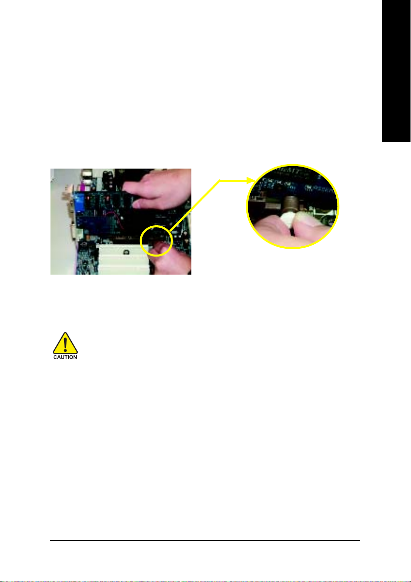
Step 3: Install expansion cards
1. Read the related expansion card's instruction document before install the expansion card into
the computer.
2. Remove your computer's chassis cover, necessary screws and slot bracket from the computer.
3. Press the expansion card firmly into expansion slot in motherboard.
4. Be sure the metal contacts on the card are indeed seated in the slot.
5. Replace the screw to secure the slot bracket of the expansion card.
6. Replace your computer's chassis cover.
7. Power on the computer, if necessary, setup BIOS utility of expansion card from BIOS.
8. Install related driver from the operating system.
Please carefully pull out the small white- drawable bar
at the end of the AGP slot when you try to install/
AGP Card
Uninstall the AGP card. Please align the AGP card to
the onboard AGP slot and press firmly down on the slot
.Make sure your AGP card is locked by the small whitedrawable bar.
English
When an AGP 2x (3.3V) card is installed the 2X_DET will light up, indicating a non-supported
graphics card is inserted. Informing users that system might not boot up normally due to AGP 2x
(3.3V) is not supported by the chipset.
- 15 - Hardware Installation Process
Step 4: Install I/O Peripherals Cables
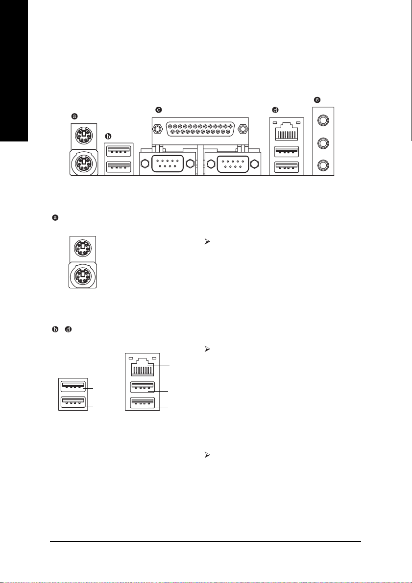
Step 4-1: I/O Back Panel Introduction
English
PS/2 Keyboard and PS/2 Mouse Connector
PS/2 Mouse Connector
(6 pin Female)
PS/2 Keyboard Connector
(6 pin Female)
/ USB/LAN Connector
USB 3
USB 2
LAN
USB 4
USB 5
To install a PS/2 port keyboard and mouse, plug
the mouse to the upper port (green) and the key-
board to the lower port (purple).
Before you connect your device(s) into USB
connector(s), please make sure your device(s) such
as USB keyboard, mouse, scanner, zip, speaker...
etc. have a standard USB interface. Also make sure
your OS supports USB controller. If your OS does
not support USB controller, please contact OS
vendor for possible patch or driver upgrade. For
more information please contact your OS or device(s)
vendors.
The provided Internet connection is Gigabit
Ethernet, providing data transfer speeds of 10/100/
1000Mbps.
- 16 -GA-8I865PE-TW Motherboard
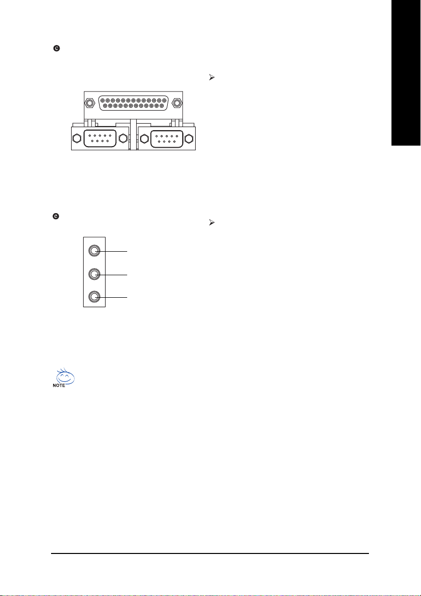
Parallel Port, Serial Ports (COMA / COMB)
English
Parallel Port
(25 pin Female)
COMA
Serial Port (9 pin Male)
Audio Connectors
Line In
Line Out
MIC In
According to your motherboard, please see the
following descriptions for the devices. The parallel
port allows connection of a printer, scanner and
other peripheral devices. Mouse and modem etc.
can be connected to Serial ports.
COMB
After install onboard audio driver, you may
connect speaker to Line Out jack, microphone to
MIC In jack. Devices like CD-ROM, walkman etc.
can be connected to Line In jack.
Please note:
You can use audio software to configure 2-/4-/6-/
8-channel audio functioning. If you wish to use 8
channel audio, a SUR_CEN cable is required
(select desired setup) along with proper software
configuration. Please contact your nearest dealer
for purchase of a SUR_CEN cable.
If you want the detailed information for 2-/4-/6-/8-channel audio setup
installation, please refer to page 61.
- 17 - Hardware Installation Process
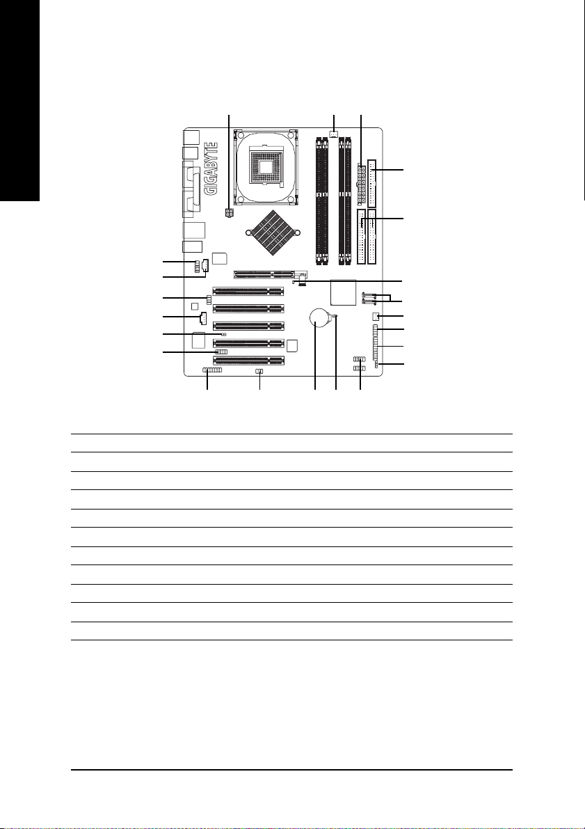
Step 4-2: Connectors & Jumper Setting Introduction
English
2
1
12
14
13
15
21
17
3
5
6
8
7
4
20
10
9
1) ATX_12V
2) ATX (Power Connector)
3) CPU_FAN
4) SYS_FAN
5) FDD
6) IDE1 / IDE2
7) SATA0 / SATA1
8) 2X_DET
9) PWR_LED
10) F_PANEL
11) B AT
19
16
11
18
22
12) F_AUDIO
13) SUR_CEN
14) CD_IN
15) AUX_IN
16) SPDIF_IO
17) IR_CIR
18) F_USB1 / F_USB2
19) GAME
20) INFO_LINK
21) CI
22) CLR_CMOS
- 18 -GA-8I865PE-TW Motherboard
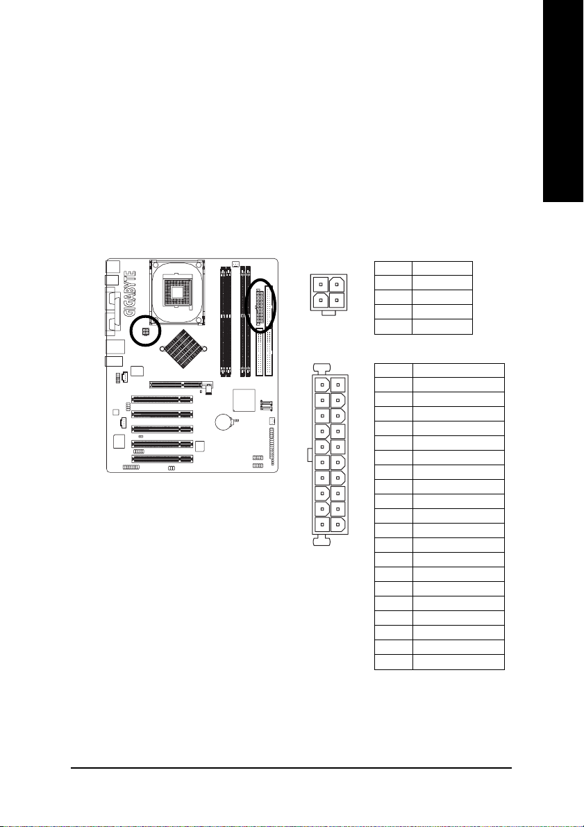
1/2) ATX_12V/ATX (Power Connector)
With the use of the power connector, the power supply can supply enough stable power to all the
components on the motherboard. Before connecting the power connector, please make sure that all
components and devices are properly installed. Align the power connector with its proper location on
the motherboard and connect tightly.
The ATX_12V power connector mainly supplies power to the CPU. If the ATX_12V power connector
is not connected, the system will not start.
Caution!
Please use a power supply that is able to handle the system voltage requirements. It is
recommended that a power supply that can withstand high power consumption be used (300W or
greater). If a power supply is used that does not provide the required power, the result can lead to an
unstable system or a system that is unable to start.
Pin No. Definition
2
4
11
20
1
1 GND
2 GND
3
3 +12V
4 +12V
Pin No. Definition
1 3.3V
1
2 3.3V
3 GND
4 VCC
5 GND
6 VCC
7 GND
8 Power Good
9 5V SB(stand by +5V)
10 +12V
10
11 3.3V
12 -12V
13 GND
14 PS_ON(softOn/Off)
15 GND
16 GND
17 GND
18 -5V
19 VCC
20 VCC
English
- 19 - Hardware Installation Process
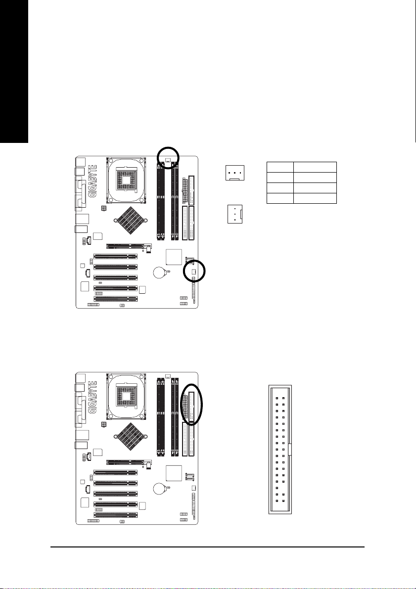
3/4) CPU_FAN / SYS_FAN (Cooler Fan Power Connector)
English
The cooler fan power connector supplies a +12V power voltage via a 3-pin power connector and
possesses a ful-proof connection design.
Most coolers are designed with color-coded power connector wires. A red power connector wire
indicates a positive connection and requires a +12V power voltage. The black connector wire is the
ground wire (GND).
Please remember to connect the power to the cooler to prevent system overheating and failure.
Caution!
Please remember to connect the power to the CPU fan to prevent CPU overheating and failure.
1
CPU_FAN
1
SYS_FAN
Pin No. Definition
1 GND
2 +12V
3 Sense
5) FDD (FDD Connector)
The FDD connector is used to connect the FDD cable while the other end of the cable connects to the
FDD drive. The types of FDD drives supported are: 360KB, 720KB, 1.2MB, 1.44MB and 2.88MB.
Please connect the red power connector wire to the pin1 position.
34
33
2
1
- 20 -GA-8I865PE-TW Motherboard
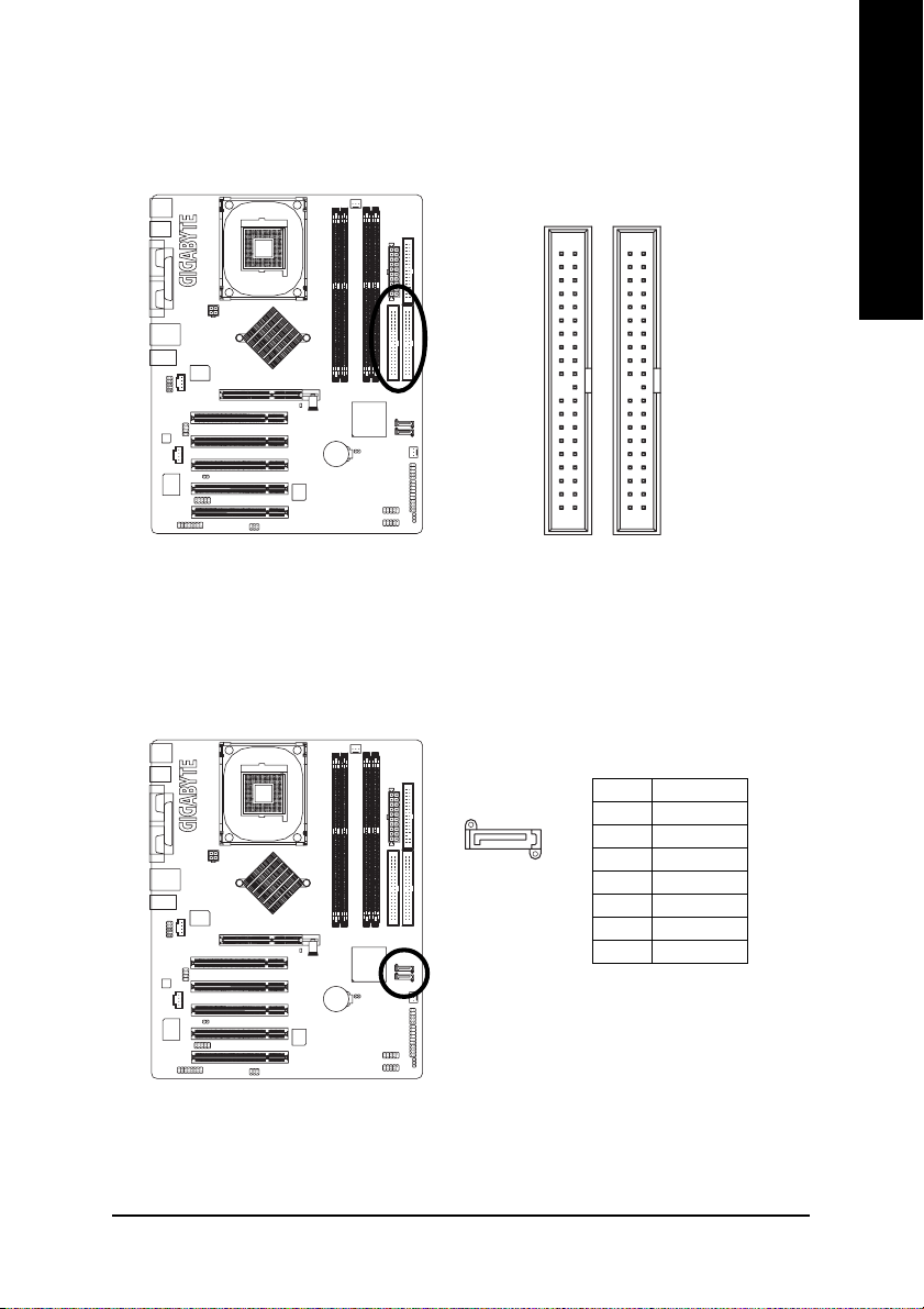
6) IDE1/ IDE2 (IDE1/IDE2 Connector)
Please connect first hard disk to IDE1 and connect CDROM to IDE2. The red stripe of the ribbon cable
must be the same side with the Pin1.
English
7) SATA0/SATA1 (Serial ATA Connector)
You can connect the Serial ATA device to this connector.
40
2
Pin No. Definition
7
1
39
1
IDE1IDE2
1 GND
2 TXP
3 TXN
4 GND
5 RXN
6 RXP
7 GND
- 21 - Hardware Installation Process
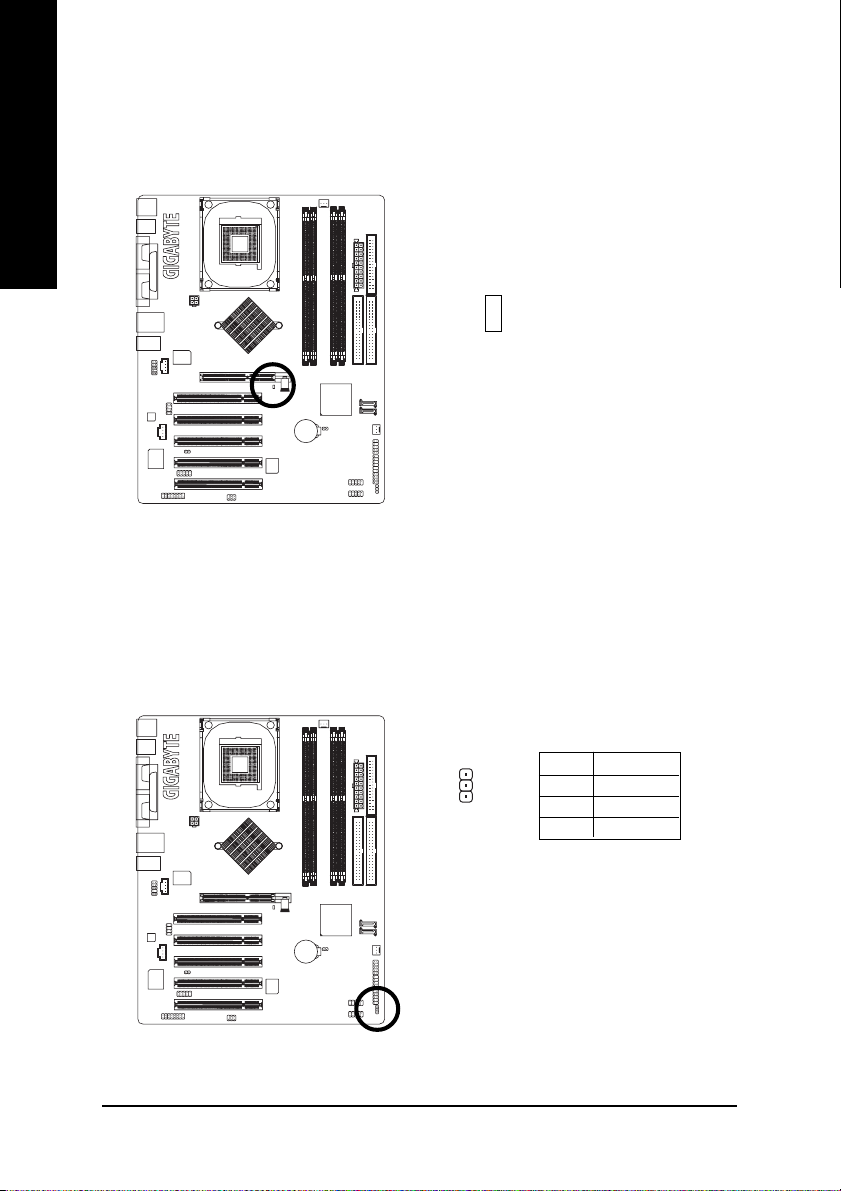
8) 2X_DET
English
9) PWR_LED
When an AGP 2X (3.3V) card is installed the 2X_DET will light up, indicating a nonsupported graphics
card is inserted. Informing users that system might not boot up normally due to AGP 2X (3.3V) is not
supported by the chipset.
-
+
PWR_LED is connect with the system power indicator to indicate whether the system is on/off. It will
blink when the system enters suspend mode. If you use dual color LED, power LED will turn to another
color.
Pin No. Definition
1 MPD+
1
- 22 -GA-8I865PE-TW Motherboard
2 MPD-
3 MPD-
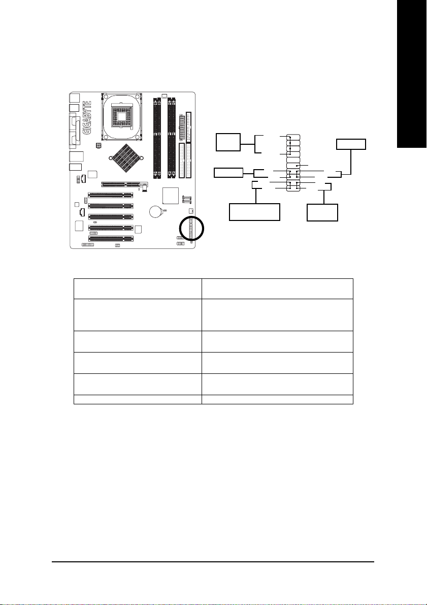
10) F_PANEL (2x10 pins connector)
Please connect the power LED, PC peaker, reset switch and power switch etc. of your chassis front panel
to the F_PANEL connector according to the pin assignment below.
20
PW+
19
NC
RES+
RESHD-
HD+
2
1
IDE Hard Disk
Active LED
SPEAK+
MSG-
MSG+
SPEAK-
PW-
Speaker
Connector
Power Switch
Message LED/Power/
Sleep LED
HD (IDE Hard Disk Active LED) Pin 1: LED anode(+)
(Blue) Pin 2: LED cathode(-)
SPEAK (Speaker Connector) Pin 1: VCC(+)
(Amber) Pin 2- Pin 3: NC
Pin 4: Data(-)
RES (Reset Switch) Open: Normal Operation
(Green) Close: Reset Hardware System
PW (Power Switch) Open: Normal Operation
(Red) Close: Power On/Off
MSG (Message LED/ Power/ Sleep LED) Pin 1: LED anode(+)
(Yellow) Pin 2: LED cathode(-)
NC ( Purple) NC
English
Reset Switch
- 23 - Hardware Installation Process
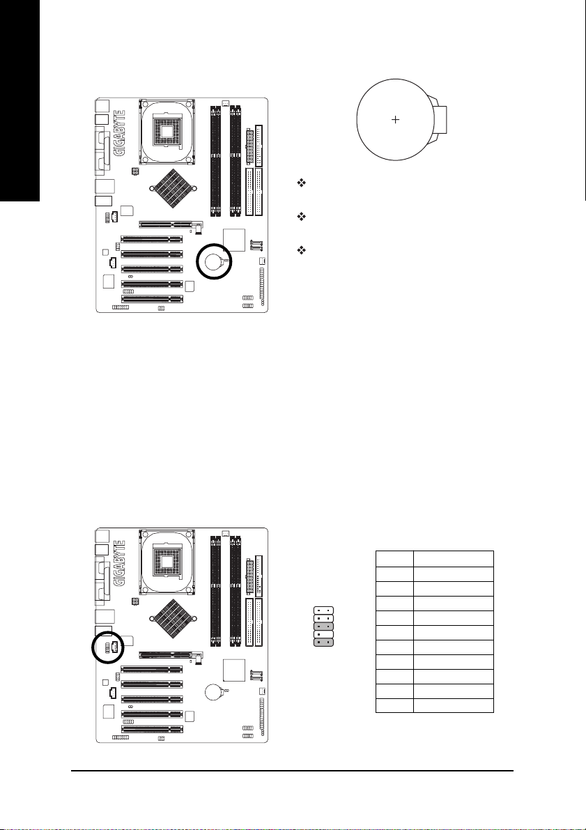
11) BAT (Battery)
English
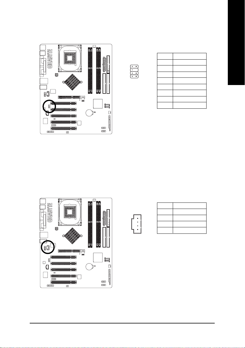
12) F_AUDIO (Front Audio Connector)
Danger of explosion if battery is incorrectly
replaced.
Replace only with the same or equivalent type
recommended by the manufacturer.
Dispose of used batteries according to the
manufacturer's instructions.
If you want to erase CMOS...
1. Please turn off the computer and unplug the
power.
2. Remove the battery, wait for 30 second.
3. Re-install the battery.
4. Plug the power cord and turn on the computer.
If you want to use Front Audio connector, you must remove 5-6, 9-10 Jumper. In order to utilize the
front audio header, your chassis must have front audio connector. Also please make sure the pin
assigment on the cable is the same as the pin assigment on the MB header. To find out if the chassis
you are buying support front audio connector, please contact your dealer.Please note, you can have
the alternative of using front audio connector or of using rear audio connector to play sound.
Pin No. Definition
1 MIC
12
109
2 GND
3 MIC_BIAS
4 Power
5 Front Audio (R)
6 Rear Audio (R)
7 Reserved
8 No Pin
9 Front Audio (L)
10 Rear Audio (L)
- 24 -GA-8I865PE-TW Motherboard
13) SUR_CEN (Surround Center Connector)
Please contact your nearest dealer for optional SUR_CEN cable.
English
14) CD_IN (CD In Connector)
Connect CD-ROM or DVD-ROM audio out to the connector.
1
78
2
1
Pin No. Definition
1 SUR OUTL
2 SUR OUTR
3 GND
4 No Pin
5 CENTER_OUT
6 BASS_OUT
7 AUX_L
8 AUX_R
Pin No. Definition
1 CD-L
2 GND
3 GND
4 CD-R
- 25 - Hardware Installation Process
 Loading...