

Gigabyte GA-8GEMT4 User Manual [ru]
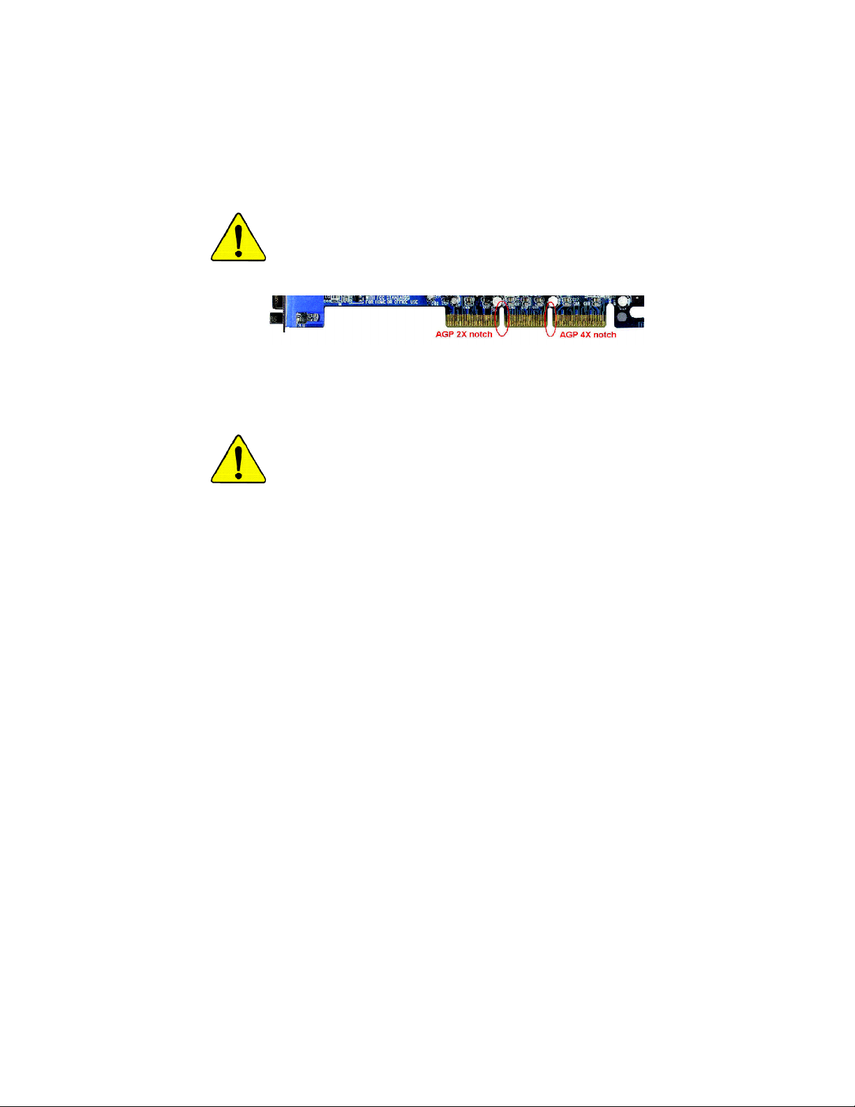
When you installing AGP card, please make sure the following
notice is fully understood and practiced. If your AGP card has
"AGP 4X notch"(show below), please make sure your AGP car d is
AGP 4X (1.5V).
Caution: AGP 2X card is not supported by Intel® 845(GE/PE) /
845(E/G) / 850(E). You might experience system unable to boot up
normally. Please inser t an AGP 4X card.
Example 1: Diamond Vipper V770 golden finger is compatible with 2X/4X
mode AGP slot. It can be switched between AGP 2X(3.3V) or 4X(1.5V)
mode by adjusting the jumper . The factory default for this card is
2X(3.3V). The GA-8GEMT4 Series (or any AGP 4X only) motherboards
might not function properly, if you install this card without switching the
jumper to 4X(1.5) mode in it.
Example 2: Some ATi Rage 128 Pro graphics cards made by “Power
Color”, the graphics card manufacturer & some SiS 305 cards, their
golden finger is compatible with 2X(3.3V)/4X(1.5V) mode AGP slot, but
they support 2X(3.3V) only. The GA-8GEMT4 Series (or any AGP 4X
only) motherboards might not function properly, If you install this card in it.
Note : Although Gigabyte's AG32S(G) graphics card is based on
ATi Rage 128 Pr o chip, the design of AG32S(G) is compliance
with AGP 4X(1.5V) specification. Therefore, AG32S (G) will work
fine with Intel® 845(GE/PE) /845(E/G) / 850(E) based motherboards.
M The author assumes no responsibility for any errors
or omissions that may appear in this document nor
does the author make a commitment to update the
information contained herein.
M Third-party brands and names are the property of
their respective owners.
M Please do not remove any labels on motherboard, this
may void the warranty of this motherboard.
M Due to rapid change in technology, some of the
specifications might be out of date before publication
of this booklet.

Ausschlager Weg 41, 1F, 20537 Hamburg, Germany
( description of the apparatus, system, installation to which it refers)
(reference to the specification under which conformity is declared)
in accordance with 89/336 EEC-EMC Directive
o EN 55011 Limits and methods of measurement
o EN 55013
o EN 55014 Limits and methods of measurement
o EN 55015 Limits and methods of measurement
o EN 55020
T EN 55022 Limits and methods of measurement
o DIN VDE 0855
o part 10
o part 12
T CE marking
o EN 60065
o EN 60335
of radio disturbance characteristics of
industrial,scientific and medical (ISM
high frequency equipment
Limits and methods of measurement
of radio disturbance characteristics of
broadcast receivers and associated
equipment
of radio disturbance characteristics of
household electrical appliances,
portable tools and similar electrical
apparatus
of radio disturbance characteristics of
fluorescent lamps and luminaries
Immunity from radio interference of
broadcast receivers and associated
equipment
of radio disturbance characteristics of
information technology equipment
Cabled distribution systems; Equipment
for receiving and/or distribution from
sound and television signals
The manufacturer also declares the conformity of above mentioned product
with the actual required safety standards in accordance with LVD 73/23 EEC
Safety requirements for mains operated
electronic and related apparatus for
household and similar general use
Safety of household and similar
electrical appliances
(Stamp)
Declaration of Conformity
We, Manufacturer/Importer
(full address)
G.B.T. Technology Träding GMbH
declare that the product
Mother Board
GA-8GEMT4
is in conformity with
o EN 61000-3-2*
T EN 60555-2
o EN 61000-3-3* Disturbances in supply systems cause
T EN 60555-3
T EN 50081-1
T EN 50082-1
o EN 55081-2
o EN 55082-2
o ENV 55104
o EN50091-2
(EC conformity marking)
o EN 60950
o EN 50091-1
Manufacturer/Importer
Date : November 15, 2002
Disturbances in supply systems cause
by household appliances and similar
electrical equipment “Harmonics”
by household appliances and similar
electrical equipment “V oltage fluctuations”
Generic em ission standard Part 1:
Residual com mercial and light industry
Generic immunity standard Part 1:
Residual com mercial and light industry
Generic em ission standard Part 2:
Industrial environment
Generic em ission standard Part 2:
Industrial environment
lmmunity requirements for household
appliances tools and similar apparatus
EMC requirements for uninterruptible
power systems (UPS)
Safety for information technology equipment
including electrical bussiness equipment
General and Safety requirements for
uninterruptible power systems (UPS)
Signature:
Name:
Timmy Huang
Timmy Huang

DECLARATION OF CONFORMITY
Per FCC Part 2 Section 2.1077(a)
Responsible Party Name:
Add ress:
Phone/Fax No:
hereby declares that the product
Produ ct Name:
Model Nu mber:
Conforms to the following specifications:
FCC Part 15, Subpart B, Section 15.107(a) and Section 15.109
(a),Class B Digital D evice
Supplementary Information:
This device complies with part 15 of the FCC Rules. Operation is
subject to the following two conditions: (1) This device may not
cause harmful and (2) this device must accept any inference received,
including that may cause undes ired operation.
Representative Person’s Name:
Signature:
G.B.T. INC. (U .S.A.)
17358 Railroad Street
City of Indu stry, CA 91748
(818) 854-9338/ (818) 854-9339
Motherboard
GA -8GEMT4
ERIC LU
Eric Lu
Date:
November 15,2002

GA-8GEMT4 Series
P4 Titan-DDR Motherboard
USER’S MANUAL
Pentium®4 Processor Motherboard
Rev. 1001
12ME-8GEMT4-1001

Table of Content
English
Item Checklist .................................................................................. 4
WARNING!.......................................................................................4
Chapter 1 Introduction.......................................................................5
Chapter 2 Hardware Installation Process ............................................ 8
Chapter 3 BIOS Setup ....................................................................23
Features Summary................................................................................................5
GA -8GEMT 4 Series Motherboard Layout........................................................7
Step 1: Install the Central Processing Unit (CPU)........................................... 9
Step1-1 : CPU Installation ..............................................................................9
Step1-2 : CPU Heat Sink Installation .............................................................. 10
Step 2: Install memory modules .......................................................................11
Step 3: Install expansion cards.........................................................................12
Step 4: Connect ribbon cables, cabinet wires, and power supply.............13
Step 4-1: I/O Back Panel Introduction ............................................................ 13
Step 4-2 : Connectors Introduction ................................................................ 15
T he Main Menu (For example: BIOS Ver. : E2).............................................24
Standard CMOS Features.................................................................................26
A dvanced BIOS Features...................................................................................29
Integrated Peripherals .......................................................................................31
Power Management Setup................................................................................35
PnP/PCI Configurations......................................................................................37
PC Health Status..................................................................................................38
Frequency /Voltage Control ................................................................................40
- 2 -GA-8GEMT4 Series Motherboard

Top Performance ................................................................................................42
Load Fail-Safe Defaults......................................................................................43
Load Optimiz ed Defaults....................................................................................44
Set Superv isor/User Password..........................................................................45
Sav e & Exit Setup.................................................................................................46
Exit Without Saving .............................................................................................47
Block Diagram .....................................................................................................49
Chapter 4 Technical Reference........................................................49
Q-Flash Introduction...........................................................................................61
@ BIOS Introduction ...........................................................................................65
Easy TuneTM 4 Introduction ...............................................................................66
2-/4-/6-Channel Audio Function Introduction.................................67
Chapter 5 Appendix........................................................................75
English
- 3 -
Table of Content

Item Checklist
þ The GA-8GEMT4 motherboard o 2 Port U SB C able x 1
English
þ IDE cable x 1/ Floppy cable x 1 o 4 Port U SB C able x 1
þ CD for motherboard driver & utility o SPDIF-KIT x 1 (SPD-KIT)
þ GA-8GEMT4 user’s manual o IEEE 1394 Cable x 1
þ I/O Shield (*) o Audio Combo Kit x 1
o Quick PC Installation Guide o Motherboard Settings Label
o RAID Manual
Computer motherboards and expansion cards contain very delicate Integrated Circuit (IC) chips. To
protect them against damage from static electricity, you should follow some precautions whenev er y ou
work on your computer.
Installing the motherboard to the chassis…
no slots to attach the spacers, do not become alarm ed you can still attach the spacers to the mounting
holes. Just cut the bottom portion of the spacers (the spacer may be a little hard to cut off, so be careful
of your hands). In this way y ou can still attach the motherboard to the base without worry ing about short
circuits. Sometimes y ou may need to use the plastic springs to isolate the screw from the motherboard
PCB surface, because the circuit w ire may be near by the hole. Be careful, don’t let the screw contact
any printed circuit write or parts on the PC B that are near the fix ing hole, otherwise it may damage the
board or cause board malfunctioning.
WARNING!
1. Unplug your computer when working on the inside.
2. Use a grounded wrist strap before handling computer components. If y ou do not have
one, touch both of your hands to a safely grounded object or to a metal object, such as
the power supply case.
3. Hold components by the edges and try not touch the IC chips, leads or connectors, or
other components.
4. Place components on a grounded antistatic pad or on the bag that came with the
components whenever the components are separated from the sy stem.
5. Ensure that the ATX power supply is sw itched off before you plug in or remove the ATX
power connector on the motherboard.
If the motherboard has mounting holes, but they don’t line up with the holes on the base and there are
“ * ” Only for GA-8GEMT4.
- 4 -GA-8GEMT4 Series Motherboard

Chapter 1 Introduction
Features Summary
Form Factor — 24.4cm x 22cm Micro-ATX size form factor , 4 layers PCB.
Motherboard — GA-8GEMT4 Series Motherboard:
GA-8GEMT4 and GA-8GEMT4-C
CPU — Socket 478 for Intel® Micro FC-PGA2 Pentium® 4 processor
— Support Intel ® Pentium ® 4 (Northwood, 0.13 m) processor
— Support Intel ® Pentium ® 4 Processor with HT Technology
— Intel Pentium®4 400/533MHz FSB
— 2nd cache depends on CPU
Chipset — Chipset Intel 845GE HOST/AGP/Controller
— ICH4 I/O Controller Hub
Memory — 2 184-pin DDR DIMM sockets
— Supports DDR333/DDR266 DIMM
— Supports up to 2GB DRAM (Max)
— Supports only 2.5V DDR DIMM
I/O Control — IT8712
Slots — 1 AGP slot 4X (1.5V) device support
— 3 PCI slot supports 33MHz & PCI 2.2 compliant
On-Board IDE — 2 IDE bus master (UDMA33/ATA66/ATA100) IDE ports
for up to 4 ATAPI devices
— Supports PIO mode3,4 (UDMA 33/ATA66/ATA100) IDE
& ATAPI CD-ROM
On-Board Peripherals — 1 Floppy port supports 2 FDD with 360K, 720K,1.2M, 1.44M
and 2.88M bytes.
— 1 Parallel port supports Normal/EPP/ECP mode
— 2 Serial ports (COMA&COMB);1 VGA Port
— 6 USB 2.0/1.1 ports (2 x Rear, 4 xFront by cable)
— 1 Front Audio Connector
— 1 IrDA connector for IR/CIR
— 1 MODEN connector(*)
— 1 Front Audio connector
MDue to (Intel 845PE/GE/GV) chipset architecture limitation, DDR 333 memory module is
only supported when using FSB 533 Pentium 4 processor. A FSB 400 Pentium 4 processor ......
will only support DDR 266 memory module
“ * ” Only for GA-8GEMT4.
- 5 -
to be continued......
Introduction
English

Hardware Monitor — CPU/System Fan Revolution detect
English
On-Board VGA — Built in Intel 845GE Chipset
On-Board Sound — Realtek ALC650 CODEC
On-Board LAN * — Builit in RTL8101L Chipset
PS/2 Connector — PS/2 Keyboard interface and PS/2 Mouse interface
BIOS — Licensed AWARD BIOS, 2M bit Flash ROM
Additional Features — PS/2 Keyboard power on by password
Overclocking — Over Clock (DDR/AGP/CPU) by BIOS
— CPU/System Fan Fail Warning
— CPU Overheat Warning
— System Voltage Detect
— Line Out / 2 front speaker
— Line In / 2 rear speaker(by s/w switch)
— Mic In / center& subwoofer(by s/w switch)
— SPDIF out
— 1 Buzzer
— CD In / AUX In / Game port
— 1 RJ 45 port
— Supports Q-Flash
— PS/2 Mouse power on
— External Modem wake up
— STR(Suspend-To-RAM)
— Wake on LAN (WOL)
— AC Recovery
— Poly fuse for keyboard over-current protection
— USB KB/Mouse wake up from S3
— Supports @BIOS
— Supports EasyTune 4
Please set the CPU host frequency in accordance with your processor’s specifications.
We don’t recommend you to set the system bus frequency over the CPU’s specification
because these specific bus frequencies are not the standard specifications for CPU,
chipset and most of the peripherals. Whether your system can run under these specific
bus frequencies properly will depend on your hardware configurations, including CPU,
Chipsets,SDRAM,Cards… .etc.
“ * ” Only for GA-8GEMT4.
- 6 -GA-8GEMT4 Series Motherboard
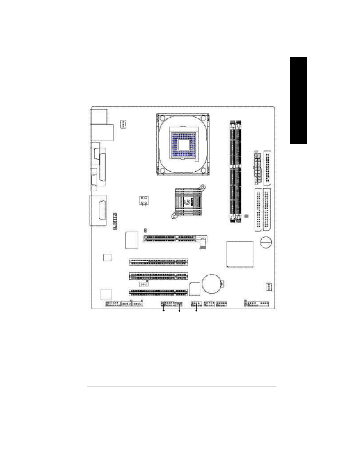
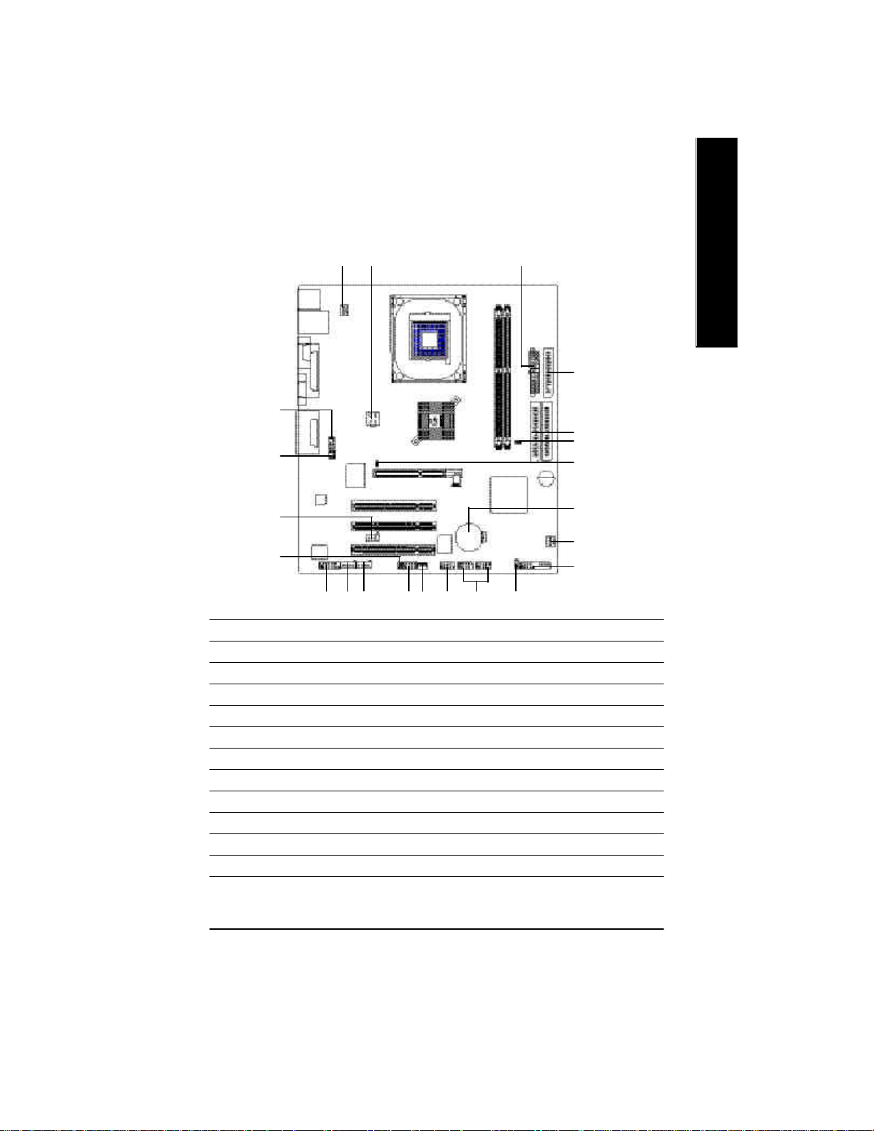
GA-8GEMT4 Series Motherboard Layout
KB_MS
CPU_FAN
USB
LAN *
COMA
LPT
SOCKET478
ATX
English
FDD
VGA
LINE_OUTMIC_IN
LINE_IN
* MODEM
GAME
CODEC
* RTL
8101L
F_AUDIO
SUR_CEN
IT8712
CD_IN
ATX_12V
AUX_IN
2X_DET
SPDIF_O
CI
IR_CIR
WOL
845GE
PCI1
PCI2
PCI3
BIOS
COMB
AGP
BAT
F_USB1
GA-8GEMT4
DDR1
F_USB2
DDR2
ICH4
PWR_LED
CLR_PWD
IDE2
F_PANEL
IDE1
BUZZER
SYS _FAN
“ * ” Only for GA-8GEMT4.
- 7 -
Introduction
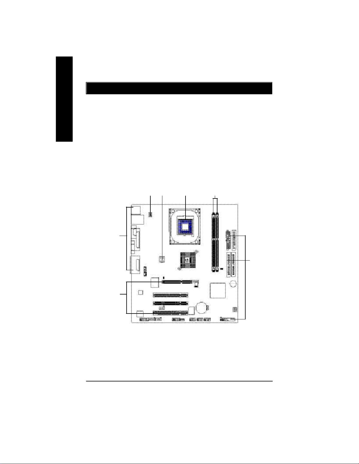
Chapter 2 Hardware Installation Process
To set up your computer, you must complete the following steps:
English
Step 1- Install the Central Processing Unit (CPU)
Step 2- Install memory modules
Step 3- Install expansion cards
Step 4- Connect ribbon cables, cabinet wires, and power supply
Step 5- Setup BIOS software
Step 6- Install supporting software tools
Step 4
Step 3
Step 1
Step 4
Step 1
Step 2
Step 4
- 8 -GA-8GEMT4 Series Motherboard

Step 1: Install the Central Processing Unit (CPU)
Step1-1 : CPU Installation
English
Angling the
rod to 65
1. Angling the rod to 65-degree maybe feel
a kind of tight, and then continue pull the
rod to 90-degree when a noise “cough”
made.
0
Pin1 indicator
3. CPU Top View
Socket
Actuation
Lever
2. Pull the rod to the 90-degree directly.
Pin1 indicator
4. Locate Pin 1 in the socket and look
for a (golden) cut edge on the CPU
upper corner. Then insert the CPU
into the socket.
M Please make sure the CPU type is supported by the motherboard.
M If you do not match the CPU socket Pin 1 and CPU cut edge well, it will cause
improper installation. Please change the insert orientation.
- 9 - Hardw are Installation Process

Step1-2 : CPU Heat Sink Installation
English
1. Hook one end of the cooler
bracket to the CPU socket first.
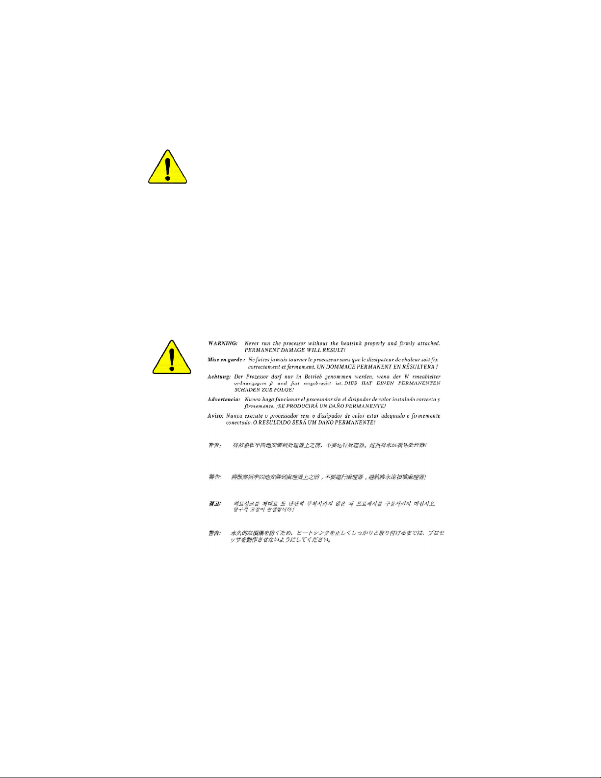
M Please use Intel approved cooling fan.
M We recommend you to apply the thermal tape to provide better heat
conduction between your CPU and heatsink.
(The CPU cooling fan might stick to the CPU due to the hardening of the
thermal paste. During this condition if you try to remove the cooling fan, you
might pull the processor out of the CPU socket alone with the cooling fan, and
might damage the processor. To avoid this from happening, we suggest you to
either use thermal tape instead of thermal paste, or remove the cooling fan with
extreme caution.)
M Make sure the CPU fan power cable is plugged in to the CPU fan connector,
this completes the installation.
M Please refer to CPU heat sink user’s manual for more detail installation
procedure.
2. Hook the other end of the
cooler bracket to the CPU
socket.
- 10 -GA-8GEMT4 Series Motherboard
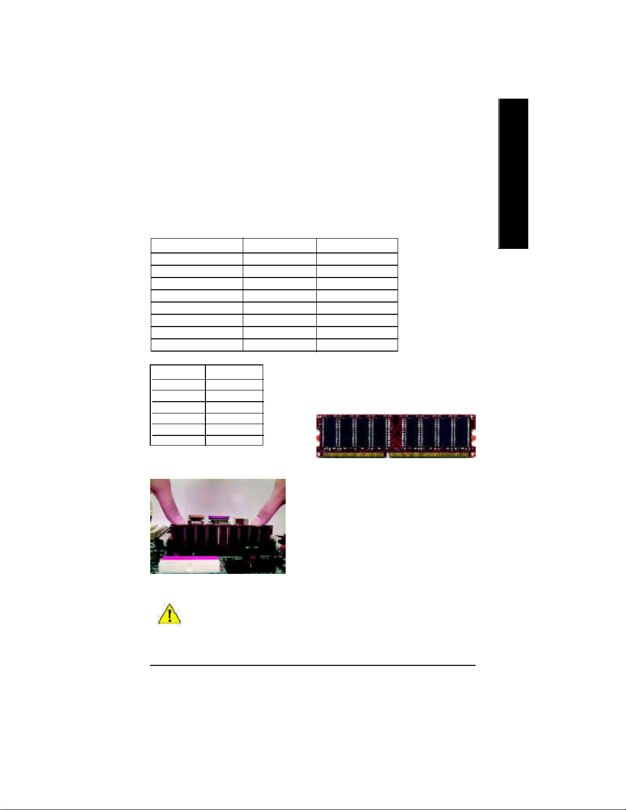
Step 2: Install memory modules
The motherboard has 2 dual inline memory module (DIMM) sockets. The BIOS will automatically
detects memory type and size. To install the memory module, just push it vertically into the DIMM socket
.The DIMM module can only fit in one direction due to the notch. Memory size can vary between
sockets.
Total Memory Sizes With Unbuffered DDR DIMM
Dev ices used on DIMM 1 DIMM x 64 / x 72 2 DIMMs x 64 / x 72
64 Mbit (2Mx 8x4 banks) 128 MBy tes 256 MBy tes
64 Mbit (1Mx 16x4 banks) 32 MBytes 64 MBy tes
128 Mbit(4Mx 8x4 banks) 256 MBy tes 512 MBy tes
128 Mbit(2Mx 16x4 banks) 64 MBytes 128 MBytes
256 Mbit(8Mx 8x4 banks) 512 MBy tes 1 GBy tes
256 Mbit(4Mx 16x4 banks) 128 MBytes 256 MBy tes
512 Mbit(16Mx 8x4 banks) 1 GBytes 2 GBytes
512 Mbit(8Mx 16x4 banks) 256 MBytes 512 MBy tes
Notes: Double-sided x16 DDR memory dev ices are not support by Intel 845E/G/PE/GE chipset.
DDR1 DDR2
S S
D S
D D
D X
S D
S X
D:Double Sided DIMM S:Single Sided DIMM
X:Not Use
DDR
English
1. The DIMM socket has a n otch, so the DIMM memory
module can only fit in one direction.
2. Insert the DIMM memory module vertically into the
DIMM socket. Then push it down.
3. Close the plastic clip at both edges of the DIMM
sockets to lock the DIMM module.
Reverse the installation steps when you wish to
remove the DIMM module.
M When STR/DIMM LED is ON, do not install/remove DIMM from socket.
M Please note that the DIMM module can only fit in one direction due to
the two notches. Wrong orientation will cause improper installation.
Please change the insert orientation.
- 11 - Hardw are Installation Process
DDR Introduction
high performance and cost-effective solution that allows easy adoption for memory vendors, OEMs and
system integrators.
English
SDRAM i nfrastructure, yet makes awesome adv ances in solving the system performance bottleneck by
doubling the memory bandwidth. DDR SDRAM will offer a superior solution and migration path from
existing S DRAM designs due to its availability, pricing and overall market support. PC2100 DDR
memory (DDR266) do ubles the data rate through reading and writing at both the rising a nd falling edge of
the clock, achiev ing data bandwidth 2X greater than PC133 when running with the same DRAM clock
frequency . With peak bandwidth of 2.664GB per second, DDR memory enables system OEMs to build
high performance and low latency DRAM subsystems that are suitable for serv ers, workstations, highend PC's and value desktop SM A sy stems. With a core voltage of only 2.5 Volts compared to
conventional SDRAM's 3.3 volts, DDR memory is a compelling solution for small form factor desktops
and notebook applications.
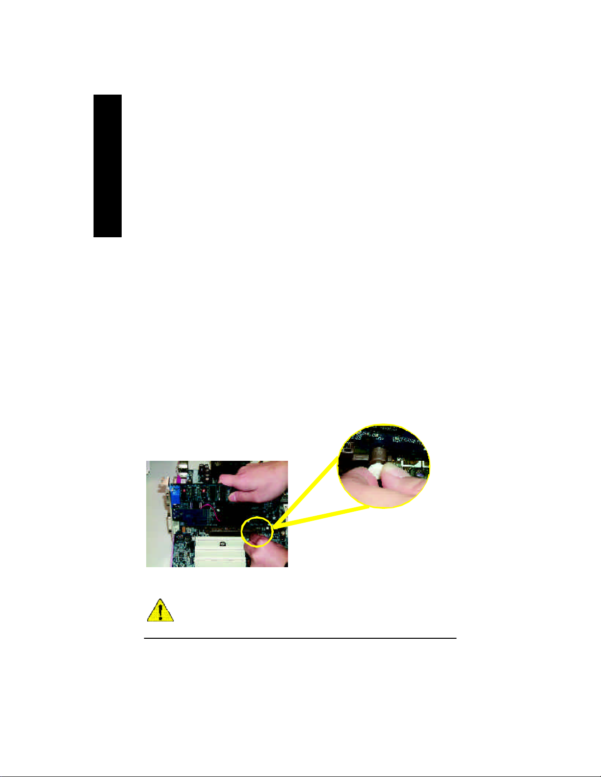
Step 3: Install expansion cards
1. Read the related expansion card’s instruction document before install the expansion card into
2. Remove your computer’s chassis cover, necessary screws and slot bracket from the computer.
3. Press the expansion card firmly into expansion slot in motherboard.
4. Be sure the metal contacts on the card are indeed seated in the slot.
5. Replace the screw to secure the slot bracket of the expansion card.
6. Replace your computer’s chassis cover.
7. Power on the computer, if necessary, setup BIOS utility of expansion card from BIOS.
8. Install related driver from the operating system.
Established on the existing SDRAM industry infrastructure, DDR (Double Data Rate) memory is a
DDR memory is a sensible evolutionary solution for the PC industry that builds on the existing
the computer.
Please carefully pull out the small whitedrawable bar at the end of the AGP slot when
you try to install/ Uninstall the AGP card.
Please align the AGP card to the onboard
AGP Card
When an AGP 2X (3.3V) card is installed the 2X_DET will light up, indicating a
non-supported graphics card is inserted. Informing users that system might not boot up
normally due to AGP 2X (3.3V) is not supported by the chipset.
AGP slot and press firmly down on the slot .
Make sure your AGP card is locked by the
small white- drawable bar.
- 12 -GA-8GEMT4 Series Motherboard
Step 4: Connect ribbon cables, cabinet wires, and power
supply
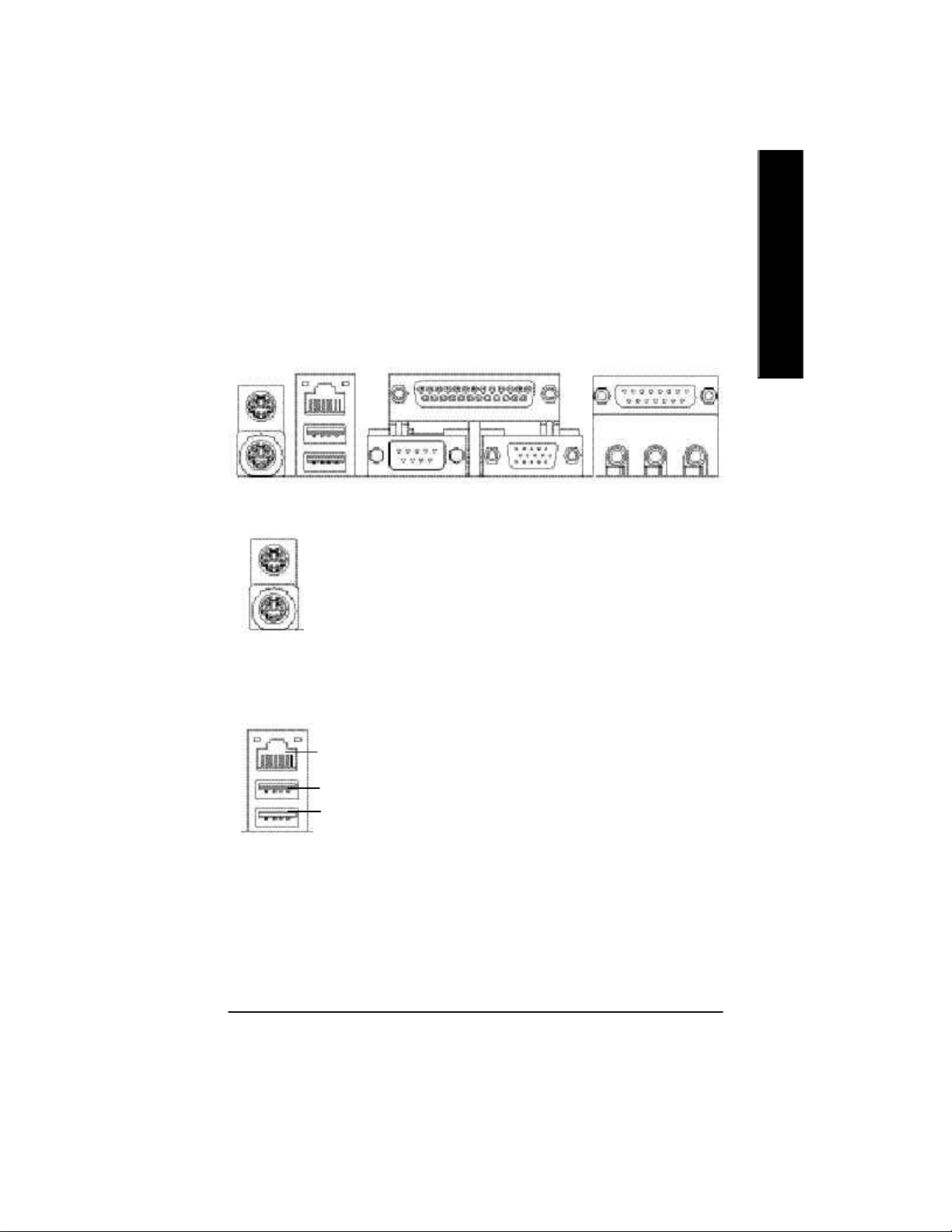
Step 4-1: I/O Back Panel Introduction
English
u
v(*) w
u PS/2 Keyboard and PS/2 Mouse Connector
PS/2 Mouse Connector
(6 pin Female)
PS/2 Keyboard Connector
(6 pin Female)
v USB Connector
LAN(*) Connector
USB 0
USB 1
ØThis connector supports standard PS/2 keyboard
and PS/2 mouse.
Ø Before you connect your device(s) into USB
connector(s), please make sure y our device(s)
such as USB keyboard,mouse, scanner, zip,
speaker..etc. Have a standard USB interface.
Also make sure your OS supports USB control ler.
If your OS does not support USB controller, please
contact OS vendor for possible patch or driver
upgra de. For more information please contact your
OS or device(s) vendors.
x
y
“ * ” Only for GA-8GEMT4.
- 13 - Hardw are Installation Process
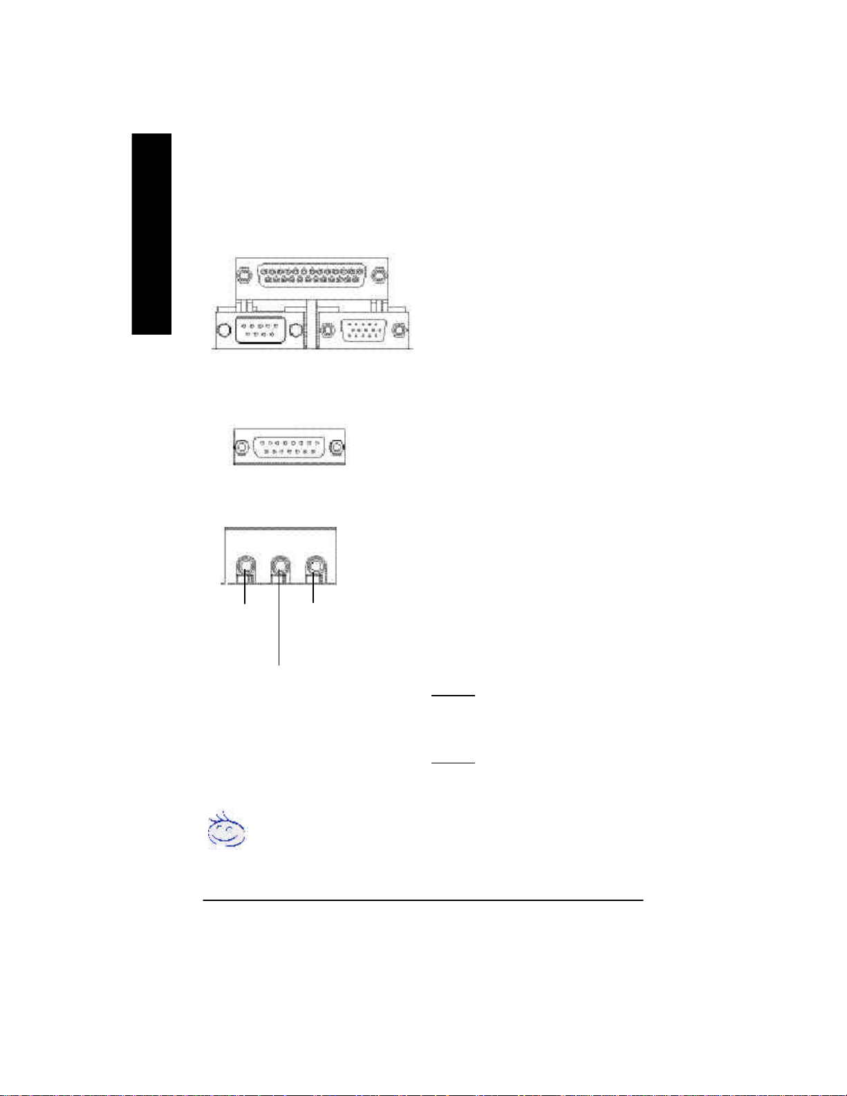
w Parallel Port and VGA Port / COMA Port
English
Parallel Port
(25 pin Female)
ØThis mainboard sutports 1 standard COM port,
1 VGA port and 1 LPT port. Device like printer
can be connected to LPT port ; mouse and
modem etc can be connected to COM port.
Serial Port
(9 pin Male)
x Game /MIDI Ports
Joystick/ MIDI (15 pin Female)
y Audio Connectors
Line Out
(Front
Speaker)
MIC In
(Center and Subw oofer)
Line In
(Rear S peaker)
VGA Port
(15 pin Female)
ØThis connector supports joystick, MIDI keyboard
and other relate audio devices.
Ø After install onboard audio driver, you may
connect speaker to Line Out jack, micro phone to
MIC In jack.
Device like CD-ROM , walkman etc can be
connected to Line-In jack.
Please note:
You are able to use 2-/4-/6- channel audio feature
by S/W selection.
If y ou want to enable 6-channel function, you have
2 choose for hardware connection.
Method1:
Connect “Front Speaker” to “Line Out”
Connect “Rear Speaker” to “Line In”
Connect “Center and Subwooferr” to “MIC Out “.
Method2:
You can refer to page 18, and contact your nearest
dealerfor optional SUR_CEN cable.
If you want the detail information for 2-/4-/6-channel audio setup
installation, please refer to page 67.
- 14 -GA-8GEMT4 Series Motherboard
Step 4-2 : Connectors Introduction
1 3 4
10
11
English
6
5
22
14
16
12813
20
7
1517 18 19
1) CPU_FAN 13) AUX_IN
2) SYS_FAN 14)SPDIF_O
3) ATX_12V 15) F_USB1/F_USB2
4) ATX 16) CI
5) IDE1/IDE2 17) IR_CIR
6) FDD 18) WOL
7) PWR_LED 19) COM B
8) 2X_DET 20) MODEM (*)
9) F_P ANEL 21) BAT
10) F_AUDIO 22) CLR_PWD
11) SUR_CEN
12) CD_IN
“ * ” Only for GA-8GEMT4.
21
2
9
- 15 - Hardw are Installation Process
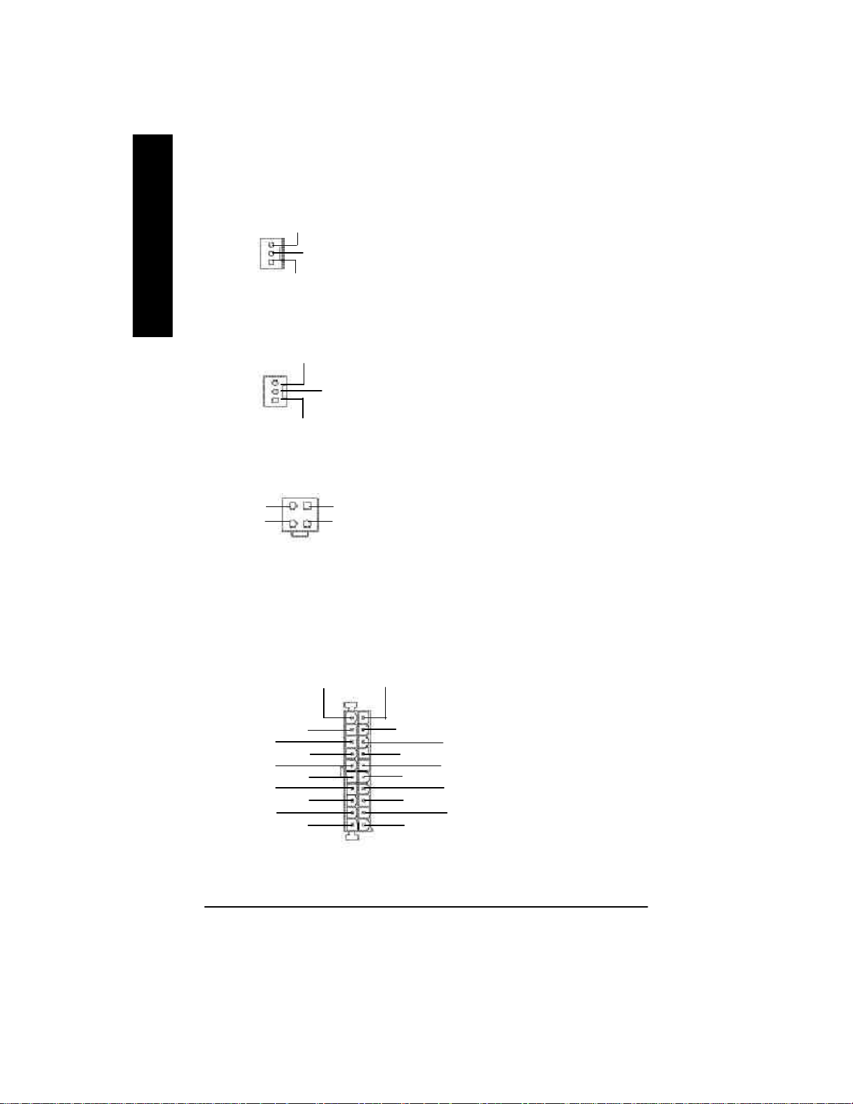
1) CPU_FAN (CPU FAN Connector) Ø Please note, a proper installation of the CPU
English
Sense
1
+12V
GND
cooler is essential to prevent the CPU from
running under abnormal condition or damaged
by overheating.The CPU fan connector
supports Max. current up to 600 mA.
2) SYS_FAN (System FAN Connector)
Sense
1
+12V
GND
3) ATX_12V (+12V Power Connector)
1
2
GND
+12V
4
GND
+12V
3
4) ATX (ATX Power)
3.3V
1
20
-12V
GND
PS-ON(Soft On/Off)
GND
GND
GND
-5V
VCC
VCC
3.3V
Ø This connector allows you to link with the
cooling fan on the system case to lower the
system temperature.
Ø This connector (ATX +12V) supplies the CPU
operation v oltage (Vcore).
If this " ATX+ 12V connector" is not
connected, sy stem cannot boot.
Ø AC power cord should only be connected to
your power supply unit after ATX power cable
and other related devices are firmly connected
to the mainboard.
3.3V
VCC
GND
GND
VCC
Power Good
+12V
GND
5V SB (Stand by +5V)
- 16 -GA-8GEMT4 Series Motherboard
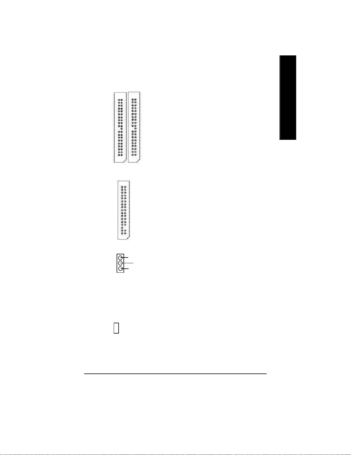
5) IDE1/ IDE2 [IDE1 / IDE2 Connector(Primary/Secondary)]
Ø Important Notice:
Please connect first harddisk to IDE1 and
connect CDROM to IDE2.
The red stripe of the ribbon cable must be
the same side with the Pin1.
1
IDE1
IDE2
6) FDD (Floppy Connector)
1
Ø Please connect the floppy drive ribbon cables
to FDD. It supports 360K,1.2M, 720K, 1.44M
and 2.88M bytes floppy disk types.
The red stripe of the ribbon cable must be the
same side with the Pin1.
English
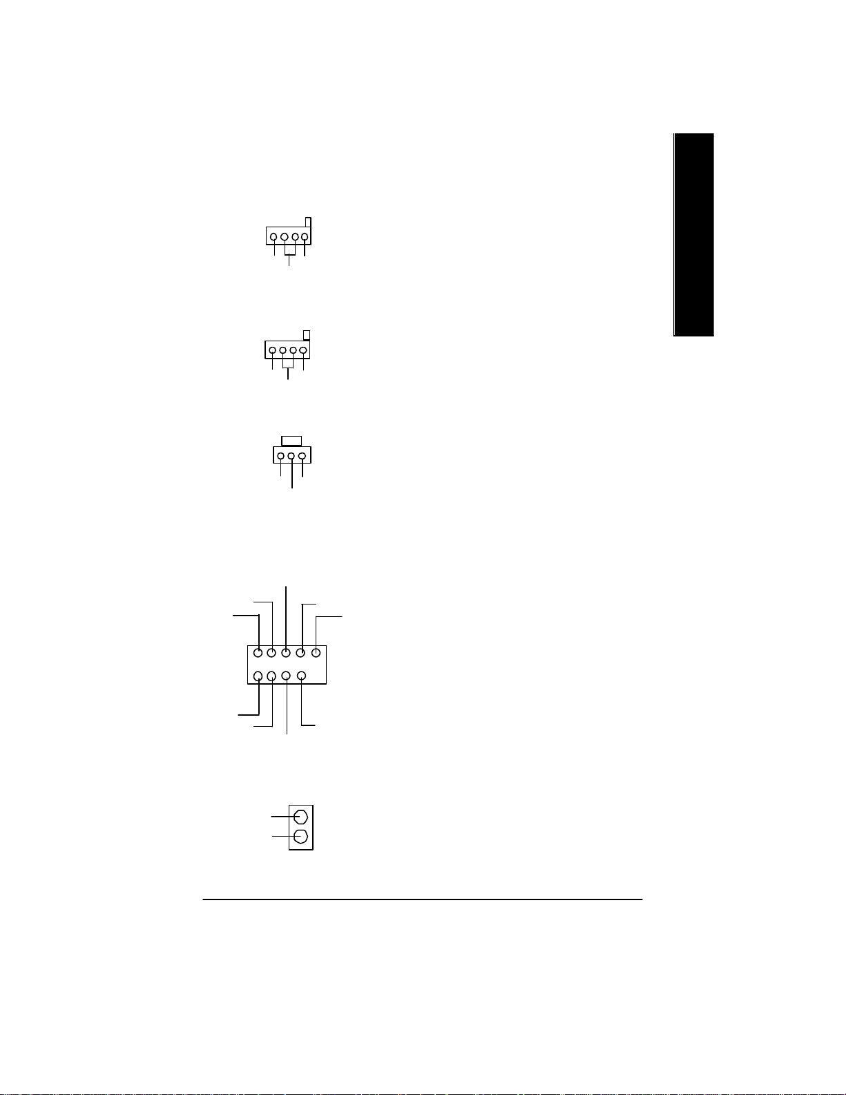
7) PWR_LED
8 ) 2X_DET
Ø PWR_LED is connect with the system power
MPD-
MPD-
MPD+
1
+ -
indicator to indicate whether the system is
on/off. It will blink when the system enters
suspend mode.
If y ou use d ual color LED, power LED will turn
to another color.
Ø When an AGP 2X (3.3V) card is installed the
2X_DET will light up, indicating a nonsupported graphics card is inserted. Informing
users that system might not boot up normally
due to AGP 2X (3.3V) is not supported by the
chipset.
- 17 - Hardw are Installation Process
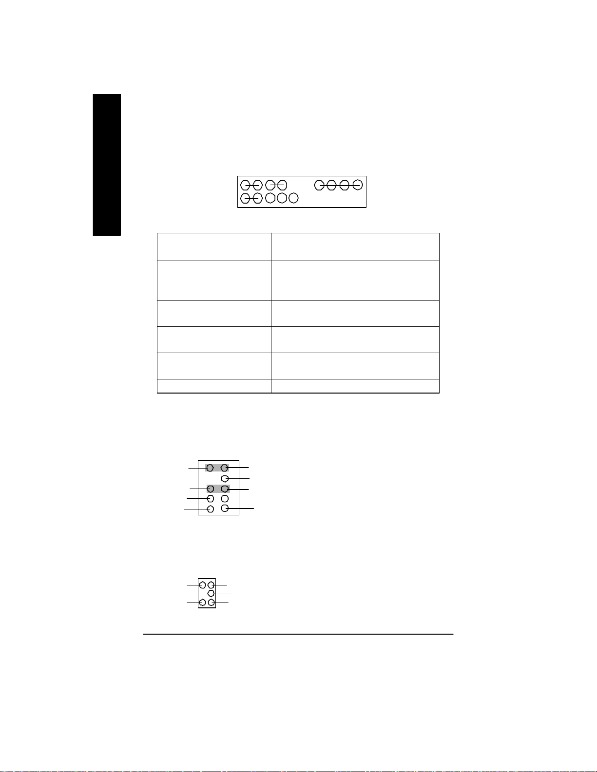
9 ) F_P ANEL (2x10 pins connector)
English
Ø Please connect the power LED, PC speaker, reset switch and power switch etc of your chassis
10) F_AUDIO (Front Audio Connector)
Rear Audio (L)
Rear Audio (R)
MSG+
1
2 20
1 19
1
HD+
HD (IDE Hard Disk Active LED) Pin 1: LED anode(+)
(Blue) Pin 2: LED cathode(-)
SPK (Speaker Connector) Pin 1: VCC(+)
(Amber) Pin 2- Pin 3: NC
RES (Reset Switch) Open: Normal Operation
(Green) Close: Reset Hardware System
PW (Soft Power Connector) Open: Normal Operation
(Red) Close: Power On/Off
MSG(Message LED/Power/ Pin 1: LED anode(+)
Sleep LED)(Yellow) Pin 2: LED cathode(-)
NC( Purple) NC
front panel to the F_PANEL connector according to the pin assignment above.
910
Front Audio (L)
Reserved
Front Audio (R)
REFPOWER
GND
1
2
MIC
PW+
MSG-
1
HD-
RES-
Pin 4: Data(-)
PW-
1
RES+
SPK+
1
NC
ØIf you want to use "Front Audio" connector ,
you must remove 5-6, 9-10 Jumper. In order to
utilize the front audio header, yourchassis must
have front audio connector . Also please make
sure the pin assigment on the cable is the same
as the pin assigment on the MB header. To find
out if the chassis you are buying support front
audio connector, please contact your dealer.
SPK-
11) SUR_CEN
SUR OUTR
Ø Please contact your nearest dealer for optional
SUR_CEN cable.
CENTER_OUTBASS_OUT
GND
SUR OUTL
1
- 18 -GA-8GEMT4 Series Motherboard
12) CD_IN (CD Audio Line In)
1
Ø Connect CD-ROM or DVD-ROM audio out
to the connector.
English
CD-R
13) AUX_IN (AUX In Connector)
AUX-R
14) SPDIF_O
CD-L
GND
AUX-L
GND
GND VCC
SPDIF Out
Ø Connect other dev ice(such as PCI TV Tunner
audio out )to the connector.
1
Ø The SPDIF output is capable of providing
digital audio to external speakers or com
1
pressed AC3 data to an external Dolby
Digital Decoder. Use this feature only when
your stereo system has digital input
function.
15 ) F_USB1/F_USB2 (F_USB1 ~ F_USB2 connector in yellow are for USB 2.0)
Ø Be careful with the polarity of the front USB
connecto r. Check the pin assignment while you
connect the front USB cable.
Please contact your nearest dealer for optional
front USB cable.
USB Dy-
Power
USB Dy+
GND
USB Over Current
1
Power
USB Dx-
USB Dx+
16) CI (CASE OPEN)
Signal
GND
GND
1
Ø This 2 pin connector allows your system to
enab le or disable the “Case Open” item in BIOS
if the system case begin remove.
- 19 - Hardw are Installation Process

17 ) IR_CIR
English
CIRRX
GND
VCC
IRRX
GND
NC
IRTX
NC
1
NC
VCC
Ø Make sure the pin 1 on the IR dev ice is
aling with pin one the connector . To
enable the IR/CIR function on the board,
you are required to purchase an option IR/
CIR module. For detail information please
contact your autherized Giga-Byte
distributor.
To use IR function only, please connect IR
module to Pin1 to Pin5.
18 ) WOL (Wake On Lan)
1
+5V SB
GND
Signal
19 ) COM B ( White connector)
NSINB
NDTRB-
NDSRB-
NCTSB-
NC
1
GND
NRIB-
NRTSB-
NDCDB-
NSOUTB
20 ) Modem ( * )
1
VDD33
VCC
GND
VAUX33
+12V
NC
NC
AC SYNC
AC RSTB
Ø This connector allows the remove servers to
manage the sy stem that installed this
mainboard via your network adapter which
also supports WOL.
Ø Be careful with the polarity of the COMB
connector. Check the pin assignment
while you connect the COMB cable.
Please contact your nearest dealer for optional
COMB cable.
Ø Please contact your nearest dealer for optional
Modem cable.
“ * ” Only for GA-8GEMT4.
- 20 -GA-8GEMT4 Series Motherboard
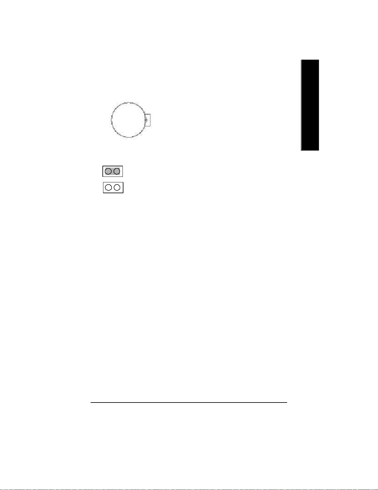
21 ) BAT (Battery)
+
CAUTION
English
v Danger of explosion if battery is incorrectly
replaced.
v Replace only with the same or equivalent
ty pe recommended by the manufacturer.
v Dispose of used batteries according to the
manufacturer’s instructions.
22 ) CLR_PWD
1
Close: Normal
Open: Clear Password1
Ø When Jumper set to "open", the password that
set will be cleared. On the contrary when
Jumper set to "close", the current status
remains.
M PS, the function offers a solution for users who
forget the password.
- 21 - Hardw are Installation Process

English
- 22 -GA-8GEMT4 Series Motherboard

Chapter 3 BIOS Setup
BIOS Setup is an ov erview of the BIOS Setup Program. The program that allows users to modify the
basic system configuration. This type of information is stored in battery-backed CMOS RAM so that it
retains the Setup information when the power is turned off.
English
ENTERING
Powering ON the computer and pressing <Del> immediately will allow you to enter Setup. If you require
more advanced BIOS settings, please go to “Advanced BIOS” setting menu.To enter Advanced BIOS
setting menu, press “Ctrl+F1” key on the BIOS screen.
CONTROL
<á> Move to previous item
<â> Move to next item
<ß> Move to the item in the left hand
<à> Move to the item in the right hand
Enter Select item
<Esc> Main Menu - Quit and not save changes into CMOS Status Page Setup Menu and
<+/PgUp> Increase the numeric value or make changes
<-/PgDn> Decrease the numeric v alue or make changes
<F1> General help, only for Status Page Setup Menu and Option Page Setup Menu
<F2> Item Help
<F3> Reserved
<F4> Reserved
<F5> Restore the previous CMOS value from CMOS, only for Option Page Setup Menu
<F6> Load the file-safe default CMOS value from BIOS default table
<F7> Load the Optimized Defaults
<F8> Q-Flash function
<F9> Reserved
<F10> Save all the CMOS changes, only for Main Menu
SETU P
K EY S
Option Page Setup Menu - Exit current page and return to Main Menu
- 23 - BIOS Setup

G ETTING HELP
The on-line description of the highlighted setup function is displayed at the bottom of the screen.
English
Press F1 to pop up a small help window that describes the appropriate keys to use and the possible
selections for the highlighted item. To exit the Help Window press <Esc>.
The Main Menu (For example: BIOS Ver. : E2)
Once you enter Award BIOS CMOS Setup Utility, the Main Menu (Figure 1) will appear on the screen.
The Main Menu allows you to select from eight setup functio ns and two exit choices. Use arro w keys to
select among the items and press <Enter> to accept or enter the sub-menu.
M ain Menu
Status Page Setup Menu / Option Page Setup Menu
CMOS Setup Utility-Copyright (C) 1984-2002 Aw ard Software
}Standard CMOS Features Top Performance
}Adv anced BIOS Features Load Fail-Safe Defaults
}Integrated Peripherals Load Optimized Defaults
}Pow er Management Setup Set Supervisor Password
}PnP/PCI Configurations Set User Passw ord
}PC Health Status Sav e & Exit Setup
}Frequency /Voltage Control Exit Without Sav ing
ESC:Quit higf:Select Item
F8: Q-Flash F10:Sav e & Exit Setup
Time, Date, Hard Disk Type...
Figure 1: Main Menu
If you can’t find the set ting you want, please press ”Ctrl+F1” to
search th e advanced option widden.
l Stand ard CMOS Features
This setup page includes all the items in standard compatible BIOS.
l Ad vanced BIOS Features
This setup page includes all the items of Award special enhanced features.
- 24 -GA-8GEMT4 Series Motherboard

l Integrated Peripherals
This setup page includes all onboard peripherals.
l Pow er Manag ement Setup
This setup page includes all the items of Green function features.
l PnP/PCI Configurations
This setup page includes all the configurations of PCI & PnP ISA resources.
l PC H ealth Status
This setup page is the System auto detect Temperature, voltage, fan, speed.
l Freq uency/Voltage Control
This setup page is control CPU’s clock and frequency ratio.
l Top Performance
If y ou wish to maximize the performance of your syste m, set "Top Performance" as "Enabled".
l Load Fail-Safe Defaults
Fail-Safe Defaults indicates the value of the system parameters which the system would
be in safe configuration.
l Load Optimized Defaults
Optimized Defaults indicates the value of the system parameters which the system would
be in best performance configuration.
l Set Sup ervisor password
Change, set, or disable password. It allows you to limit access to the system and Setup,
or just to Setup.
l Set U ser password
Change, set, or disable password. It allows you to limit access to the system.
l Save & Exit Setup
Save CMOS value settings to CMOS and exit setup.
l Exit Without Saving
Abandon all CMOS value changes and exit setup.
English
- 25 - BIOS Setup

Standard CMOS Features
English
CMOS Setup Utility-Copyright (C) 1984-2002 Aw ard Software
Standard CMOS Features
Date (mm:dd:yy) Fri, May 3 2002 Item Help
Time (hh:mm:ss) 17:56:23 Menu Level u
Change the day , month,
}IDE Primary Master None y ear
}IDE Primary Slave None
}IDE Secondary Master None <Week>
}IDE Secondary Slave None Sun. to Sat.
Driv e A 1.44M, 3.5 in. <Month>
Driv e B None Jan. to Dec.
Floppy 3 Mode Support Disabled
<Day >
Halt On All, But Keyboard 1 to 31 (or maximum
allow ed in the month)
Base Memory 640K
Ex tended Memory 130048K <Year>
Total Memory 131072K 1999 to 2098
higf: Mov e Enter:Select +/-/PU/PD:Value F10:Sav e ESC:Exit F1:General Help
F5:Prev ious Values F6:Fail-Safe Defaults F7:Optimized Defaults
Figure 2: Standard CMOS Features
C Date
The date format is <week>, <month>, <day>, <year>.
8Week The w eek, from Sun to Sat, determined by the BIOS and is display only
8Month The month, Jan. Through Dec.
8Day The day, from 1 to 31 (or the maximum allowed in the month)
8Year The y ear, from 1999 through 2098
- 26 -GA-8GEMT4 Series Motherboard
 Loading...