

Page 1
Phone/Fax No: (818) 854- 9338/ (818) 854-9339
hereby declare s that the product
Product Name:
Model Number:
Mother Board
Signature:
Date: Jul.26,2001
GA- 7ZXE
FCC Compliance Statement:
DECLARATION OF CONFORMITY
Per FCC Part 2 Section 2. 1077(a)
Responsible Party Name: G.B.T. INC.
Address: 18305 Valley Blvd., Suite#A
LA Puent, CA 91744
Conforms to the following specifications:
FCC Part 15, Subpart B, Section 15.107(a) and Section 15.109(a),
Class B Digital Device
Supplementary Information:
This device complies with part 15 of the FCC Rules. Operation is subject to the
following two conditions: (1) This device may not cause harmful
and (2) this device must accept any inference received, including
that may cause undesired operation.
Representative Person's Name: ERIC LU
Eric Lu
determined by turning the equipment off and on, the user is encouraged to try to
correct the interference by one or more of the following measures:
-Reorient or relocate the receiving antenna
-Move the equipment away from the receiver
-Plug the equipment into an outlet on a circuit different from that to which
the receiver is connected
This equipment has been tested and found to
comply with limits for a Class B digital device,
pursuant to Part 15 of the FCC rules. These
limits are designed to provide reasonable
protection against harmful interference in
residential installations. This equipment
generates, uses, and can radiate radio
frequency energy, and if not installed and used
in accordance with the instructions, may cause
harmful interference to radio communications.
However, there is no guarantee that interference
will not occur in a particular installation. If this
equipment does cause interference to radio or
television equipment reception, which can be
You are cautioned that any change or modifications to the equipment not
expressly approve by the party responsible for compliance could void Your
authority to operate such equipment.
This device complies with Part 15 of the FCC Rules. Operation is subjected to
the following two conditions 1) this device may not cause harmful interference
and 2) this device must accept any interference received, including interference
that may cause undesired operation.
-Consult the dealer or an experienced radio/television technician for
additional suggestions
Page 2
Declaration of Conformity
We, Manufacturer/Importer
(full address)
G.B.T. Technology Träding GMbH
Ausschlager Weg 41, 1F, 20537 Hamburg, Germany
( description of the apparatus, system, installation to which it refers)
(reference to the specification under which conformity is declared)
in accordance with 89/336 EEC-EMC Directive
EN 55011 Limits and methods of measurement EN 61000-3-2* Disturbances in supply systems caused
of radio disturbance characteristics of EN60555-2 by household appliances and similar
industrial, scientific and medical (ISM electrical equipment “Harmonics”
high frequency equipment
EN55013 Limits and methods of measurement EN61000-3-3* Disturbances in supply systems caused
of radio disturbance characteristics of EN60555-3 by household appliances and similar
broadcast receivers and associated electrical equipment “Voltage fluctuations”
equipment
EN 55014 Limits and methods of measurement EN 50081-1 Generic emission standard Part 1:
of radio disturbance characteristics of Residual, commercial and light industry
household electrical appliances,
portable tools and similar electrical EN 50082-1 Generic immunity standard Part 1:
apparatus Residual, commercial and light industry
EN 55015 Limits and methods of measurement EN 55081-2 Generic emission standard Part 2:
of radio disturbance characteristics of Industrial environment
fluorescent lamps and luminaries
EN 55020 Immunity from radio interference of EN 55082-2 Generic immunity standard Part 2:
broadcast receivers and associated Industrial environment
equipment
EN 55022 Limits and methods of measurement ENV 55104 Immunity requirements for household
of radio disturbance characteristics of appliances tools and similar apparatus
information technology equipment
DIN VDE 0855 Cabled distribution systems; Equipment EN 50091- 2 EMC requirements for uninterruptible
part 10 for receiving and/or distribution from power systems (UPS)
part 12 sound and television signals
declare that the product
Mother Board
GA-7ZXE
is in conformity with
CE marking (EC conformity marking)
The manufacturer also declares the conformity of above mentioned product
with the actual required safety standards in accordance with LVD 73/23 EEC
EN 60065 Safety requirements for mains operated EN 60950 Safety for information technology equipment
electronic and related apparatus for including electrical business equipment
household and similar general use
EN 60335 Safety of household and similar EN 50091-1 General and Safety requirements for
electrical appliances uninterruptible power systems (UPS)
Signature
Date : Jul. 26, 2001 Name : Rex Lin
(Stamp)
Manufacturer/Importer
:
Rex Lin
Page 3

7ZXE
AMD AthlonTM/Duron
中文安裝手冊
AMD AthlonTM/DuronTM Socket A 處理器主機板
TM
Socket A 處理器
主機板
REV 1.1 First Edition
12MC-7ZXE-1101
Page 4

Page 5

使用手冊之組織架構
此安裝手冊是依下列章節組織而成:
1) 版本修改摘要 使用手冊版本修改資訊
2) 清點附件 產品盒內附件清單
3) 特色彙總 主機板詳細資訊和規格
4) 安裝指南 主機板安裝指南
5) 效能測試和晶片組功能方塊圖 主機板效能測試結果和晶片組功能方
塊圖
6) Suspend to RAM STR 安裝說明
7) Q-Flash BIOS 燒錄工具程式 Q-Flash BIOS 燒錄工具程式介紹
8) @BIOSTM 及 EasyTuneIIITM @BIOSTM 及 EasyTuneIIITM功能介紹
9) BIOS 功能設定 BIOS功能設定指南
10) 技術支援送修單 記錄使用配備,提供快速服務
11) 附錄 參考資料
Page 6

Page 7

目 錄
版本修改摘要
清點附件
特色彙總
7ZXE 主機板的元件配置圖
安裝指南
插座及接腳設定的快速安裝指南
效能測試
晶片組功能方塊圖
安裝 Suspend to RAM 功能
Q-Flash BIOS 燒錄工具程式介紹
@BIOSTM功能介紹
EasyTuneIIITM功能介紹 P.35
P. 1
P. 2
P. 3
P. 4
P. 6
P.12
P.24
P.25
P.26
P.32
P.34
BIOS 組態設定目錄
技術支援送修單
附錄
P.36
P.67
P.68
Page 8

Page 9

7ZXE 主機板
版本修改摘要
版本 修改摘要 日期
1.01
1.1
本手冊所有提及之商標與名稱皆屬該公司所有。
主機板上的任何貼紙請勿自行撕毀,否則會影響到產品的保固服務.
本手冊若有任何內容修改,恕不另行通知。
7ZXE 主機板中文安裝手冊首版發行。
7ZXE 主機板中文安裝手冊首版發行。
2001 年 9 月 5 日 台北,台灣
Aug.2001
Sep.2001
Page 10

清點附件
þ 7ZXE 主機板一片
þ 軟、硬碟插座排線各一條
þ 主機板驅動程式光碟片(VUCD)
þ 7ZXE 中文使用手冊
清點附件
Page 11

7ZXE 主機板
特色彙總
規格 主機板採四層設計 ATX 規格 30.4 公分x 18.3 公分
CPU Ÿ AMD AthlonTM/DuronTM (K7)Socket A 處理器
Ÿ 256K/64K 第二層快取記憶體內含於 CPU
Ÿ 支援 600MHz ~ 1.5GHz 以上
晶片組
時脈產生器
記憶體
I/O 控制器
擴充槽 Ÿ 5 個 PCI插槽支援 33MHz及符合 PCI 2.2規格
內建 IDE
內建周邊設備
硬體監控
PS/2 插座
內建音效
BIOS
附加特色
Apollo KT133A, consisting of:
Ÿ VT8363A Memory/AGP/PCI Controller (PAC)
Ÿ VT82C686B PCI Super-I/O Integrated Peripheral
Controller (PSIPC)
Ÿ ICS 94236AF
100 / 133 MHz system bus speeds
Ÿ 3 個 168-pin DIMM 插槽
Ÿ 支援 PC-100 / PC-133 SDRAM 及 VCM SDRAM
Ÿ 最高可支援到 1.5GB 記憶體
Ÿ 僅支援 3.3V SDRAM DIMM
Ÿ VT82C686B
Ÿ 1 個 AGP 插槽支援 4X mode 及符合 AGP 2.0 規格
Ÿ 1 ISA 插槽 (選擇性的功能)
Ÿ 2 IDE bus master (UDMA 33/ATA 66/ATA 100) IDE 埠
可連接 4 ATAPI 裝置
Ÿ 支援 PIO mode 3、4,UDMA 33/ATA 66/ATA 100 IDE
Ÿ 及 ATAPI CD-ROM
Ÿ 1 個軟碟插座支援兩台磁碟機
(360K ,720K ,1.2M ,1.44M 及 2.88M bytes)
Ÿ 1 個並列插座可支援 Normal/EPP/ECP 模式
Ÿ 2 個串列插座(COM A 及 COM B)
Ÿ 4 個 USB 插座
Ÿ 系統電壓自動偵測
Ÿ PS/2
Ÿ AC’97 CODEC
Ÿ Line In / Line Out / Mic In Game Port / CD In
Ÿ 使用經授權 AMI BIOS, 2M bit 快閃記憶體
Ÿ 網路遠端開機功能
Ÿ 包含 2 個散熱風扇電源接腳
Ÿ 鍵盤過電流保護
Ÿ 支援 @BIOS™ 和 EasyTuneIII™
鍵盤連接埠及 PS/2 滑鼠連接埠
Page 12
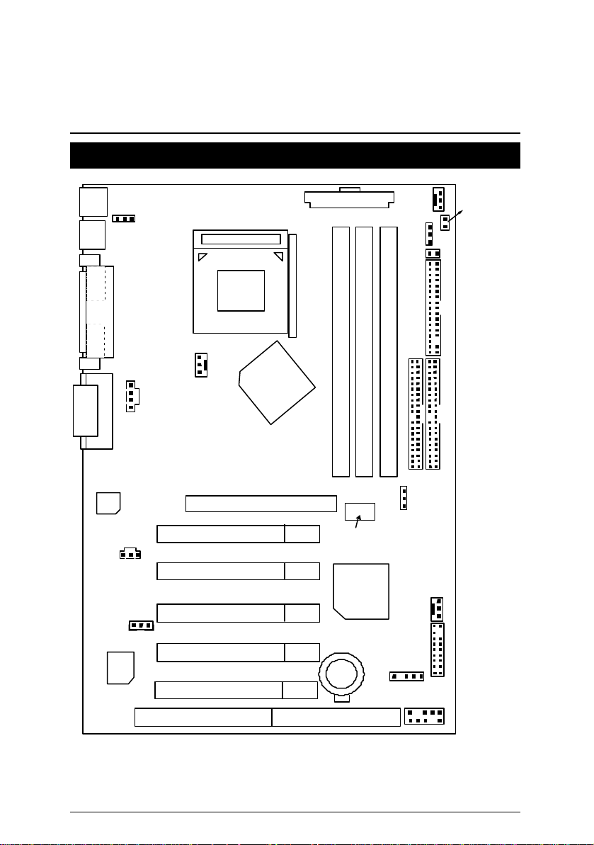
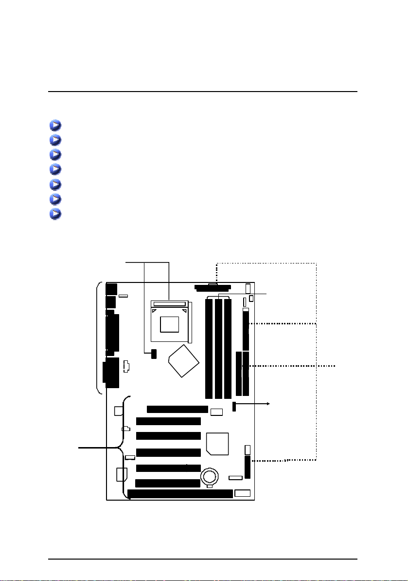
7ZXE 主機板的元件配置圖
BAT1
7ZXE (Rev.1.01) 主機板的元件配置圖
PS/2
USB_ON
USB1
COM A
Socket A
CPU
LPT
COM B
ATX POWER
PWR_FAN
RAM_LED
STR_EN
STR_LED
FLOPPY
AC’97
GAME & AUDIO
BIOS
CD_IN
SPDIF
WOL
ISA 1
PCI1
PCI2
PCI3
PCI4
PCI5
CPU_FAN
AGP 1
VT8363A
7ZXE
DIMM2
DIMM1
Clock
Generator
VT82C
686B
IR
IDE1
DIMM3
CLK_JP
IDE2
SYS_FAN
F_PANEL
USB2
Page 13
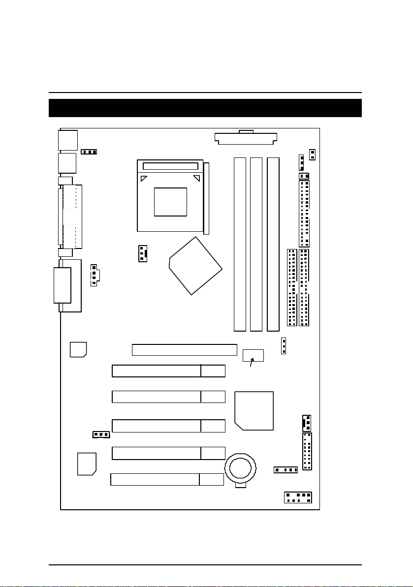
7ZXE 主機板
BAT1
7ZXE 主機板的元件配置圖
PS/2
USB_ON
ATX POWER
RAM_LED
USB1
COM A
COM B
GAME & AUDIO
AC’97
LPT
BIOS
STR_EN
STR_LED
Socket A
CPU
FLOPPY
CPU_FAN
CD_IN
VT8363A
IDE1
IDE2
7ZXE
DIMM3
DIMM2
DIMM1
WOL
PCI1
PCI2
PCI3
PCI4
PCI5
AGP 1
Clock
Generator
VT82C
686B
IR
CLK_JP
SYS_FAN
F_PANEL
USB2
Page 14

安裝指南
安裝指南
開始
警告!
主機板由許多精密的積體電路及其他元件所構成,這些積體電路很
容易因為遭到靜電影響而損失。所以請在正式安裝前,做好下列準
備。
1. 請將電腦的電源關閉,最好拔除電源插頭。
2. 拿取主機板時請儘量避免觸碰金屬接線部份。
3. 拿取積體電路元件(CPU、RAM)時,最好能夠戴上有防靜電手環。
4. 在積體電路未安裝前,需將元件置放在靜電墊或防靜電袋內。
5. 當您將主機板中的 ATX 電源供應器插座上的插頭拔除時,請確認電源供應器
的開關是關閉狀況。
安裝主機板至機殼中…
大多數電腦機殼的底部會有多個固定孔孔位,可使主機板確實固定並且不會短
路。
請小心不要讓螺絲接觸到任何PCB板上的線路或零件,當印刷電路主機板表面線
路接近固定孔時,您可使用塑膠墊片來讓螺絲與主機板表面隔離過,避免造成主
機板損壞或故障。
Page 15
7ZXE 主機板
請依據下列方式,完成電腦的安裝:
步驟 1 – 參考手冊內容調整 Jumper
步驟 2 – 安裝中央處理器 (CPU)
步驟 3 – 安裝記憶體模組
步驟 4 – 安裝所有介面卡
步驟 5 – 連接所有訊號線、排線、電源供應線及面版控制線
步驟 6 – 完成 BIOS 組態設定
步驟 7 – 安裝軟體驅動程式
步驟
2
步驟
5
步驟
3
步驟
5
步驟
步驟
1
4
Page 16
安裝指南
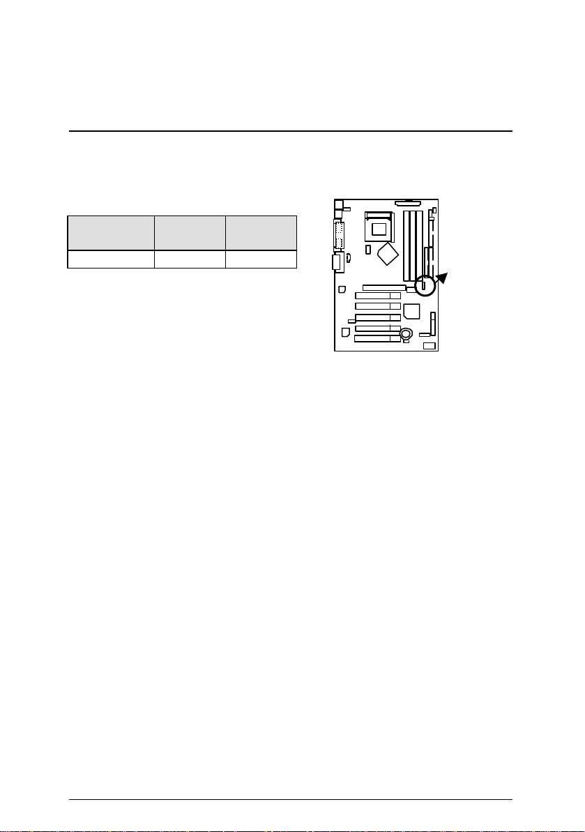
CLK_JP
CPU速度設定
系統速度可以選擇設定為 100~133MHz。您可以用Jumper(CLK_JP)來選擇系統速度。
(倍頻取決於 CPU 設計)
CPU CLK
Frequency
100MHz 133MHz
CLK_JP 2-3 Close 1-2 Close
MAMD CPU 散熱裝置安裝:
在你啟動電腦之前,請先確認是否裝妥散熱裝置,否則將導致中央處理器過熱而
燒毀。
Page 17
7ZXE 主機板
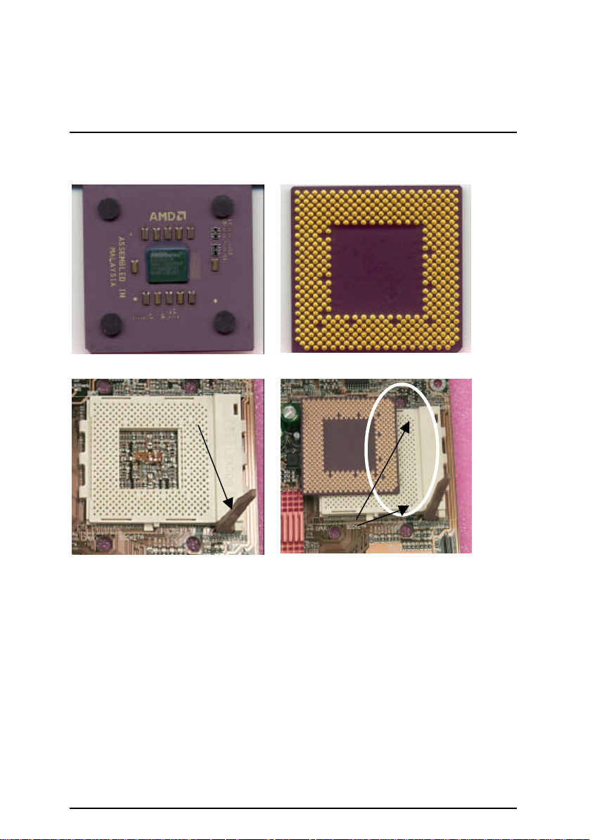
安裝中央處理器(CPU)
請確認您使用的中央處理器為本主機板的支援範圍。
中央處理器正面
連桿
1.將連桿向外拉出並昇起。
中央處理器背面
斜角
2.中央處理器的斜角對齊於插座的斜腳後
平行插入插座 (中央處理器安裝是有方向
性的)。
Page 18
安裝指南
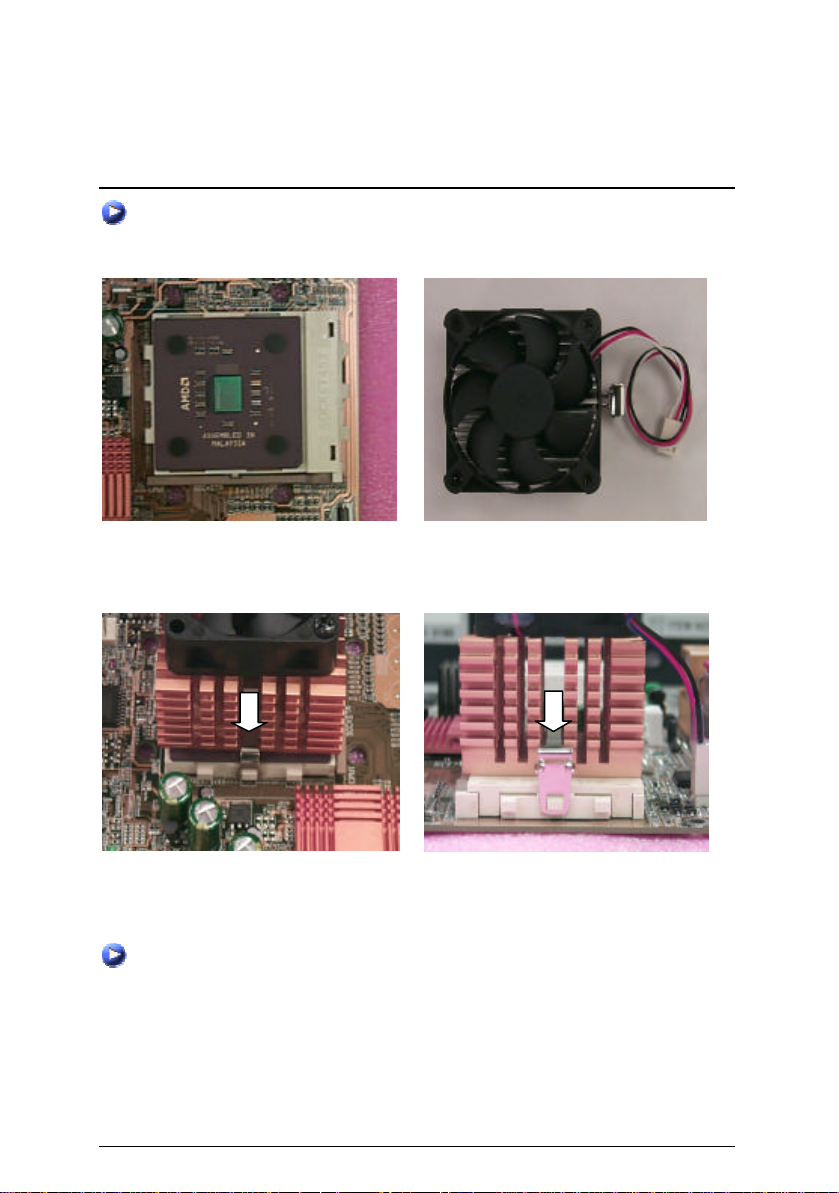
AMD 中央處理器散熱裝置安裝:
在你啟動電腦之前,請先確認是否裝妥散熱裝置,否則將導致中央處理器過熱而
燒毀。
3.將連桿往下按至原位
(塗抹散熱膏於處理器上,可使處理器與
散熱風扇之間能達到較好的散熱效果。
以上動作請參考散熱風扇的使用手冊。)
5.依箭頭方向依序將風扇確實扣緊。
6.確認中央處理器散熱風扇電源線接至中央處理器散熱風扇接頭,安裝完成。
細部安裝步驟請參考散熱風扇的使用手冊。
4.使用經 AMD 認證過的散熱風扇。
Page 19
7ZXE 主機板
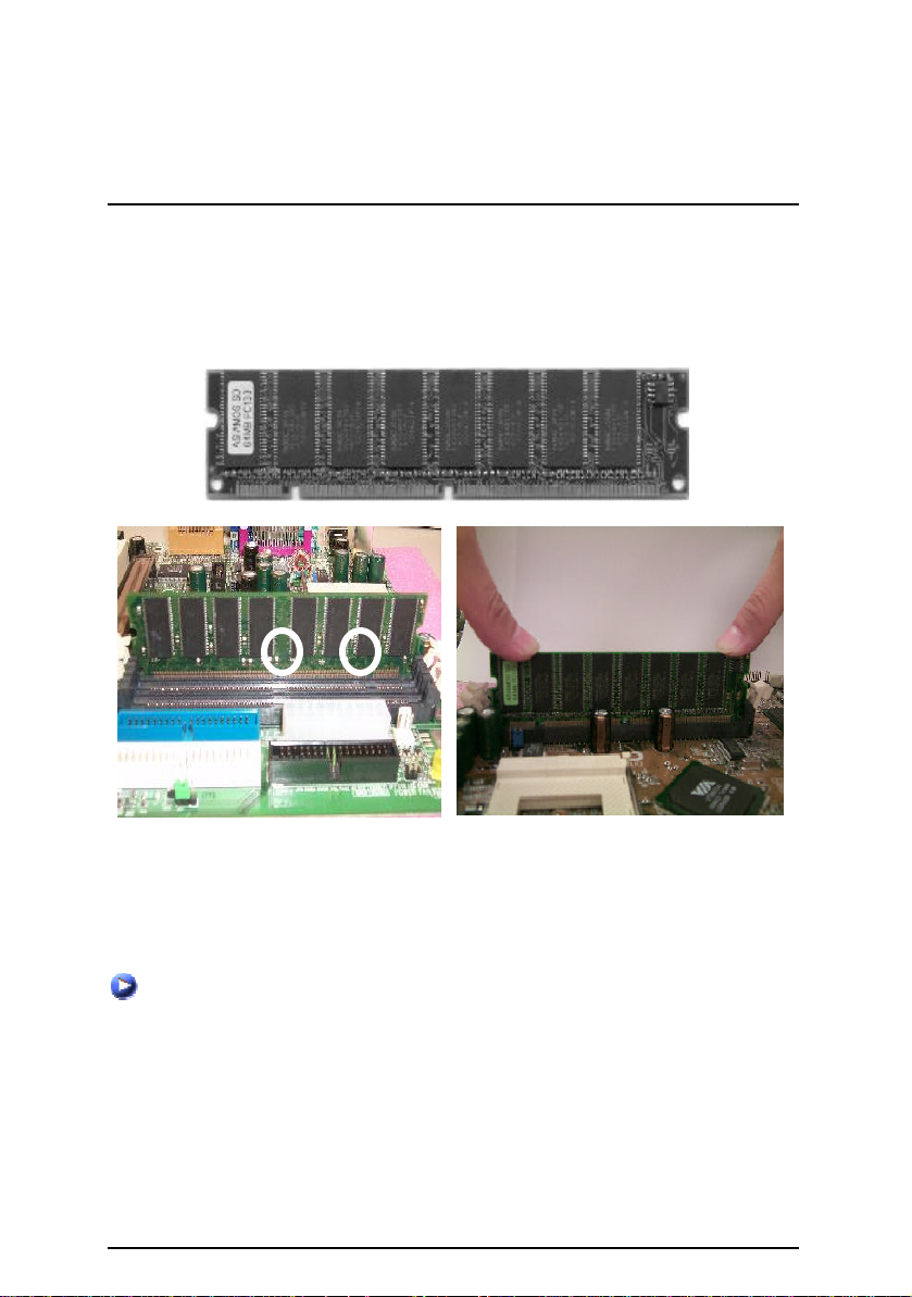
DIMM
記憶體安裝指南
本主機板有3個(DIMM)擴充槽. BIOS會自動偵測記憶體的規格及其大小. 安裝記憶
體只需將DIMM插入其插槽內即可, 由於記憶體模組有兩個凹痕, 所以只能以一個
方向插入,在不同的插槽,記憶體大小可以不同,建議使用相同顆粒的記憶體模組,
如:NEC, Toshiba, PQI, Winbond…等.
SDRAM
1. 記憶體模組有兩個凹痕,所以只能以
一個方向插入.
3. 將卡楯向內推,確實卡住記憶體模組 DIMM。一旦固定位置,兩旁的卡楯便
自動卡住記憶體模組予以固定。試著輕輕搖動記憶體模組,若不搖晃則裝置
成功.
當您要移除 DIMM 記憶體模組,請反向操作以上步驟.
2. 確認 DIMM 記憶體模組安裝於
插槽內,然後下壓.
Page 20

安裝指南
插座及接腳設定的快速安裝指南 頁數
插座
第一組IDE插座 / 第二組IDE插座
串列埠A /串列埠B/印表機並列埠插座
遊戲搖桿控制埠及音源插座
ATX Power (電源插座)
CPU_FAN (CPU散熱風扇電源接腳)
CD_IN (光碟機音源接腳)
Floppy Port (軟碟機插座)
IR (紅外線接腳)
PWR_FAN (電源散熱風扇電源接腳)
PS/2鍵盤及PS/2滑鼠插座
SPDIF P.18
SYS_FAN (系統散熱風扇電源接腳)
STR_LED /RAM_LED(進階省電模式指示燈/記憶體電源指示燈)
USB1 (通用串列埠插座)
USB2 (前端通用串列埠插座)
WOL (網路卡喚醒功能接腳)
接腳定義說明
BAT 1 (電池)
F_PANEL (2x11 Pins 接腳)說明
USB_ON (通用串列埠設備喚醒功能接腳)
STR_EN (進階省電模式開關)
P.13
P.16
P.13
P.16
P.13
P.19
P.17
P.15
P.20
P.18
P.14
P.17
P.20
P.14
P.15
P.19
P.21
P.23
P.21
P.22
P.22.
Page 21
7ZXE 主機板
AC
(110/220V)
ATX
電源插座,並接好其相關配備才可以將
插座
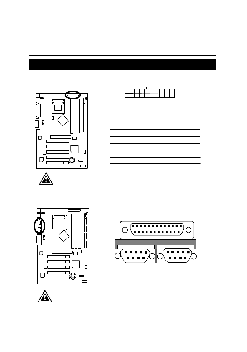
ATX Power 電源插座
20
10
接腳
3,5,7,13,15-17
1,2,11 3.3V 電壓
4,6,19,20
10 +12V 電壓
12 -12V 電壓
18 -5V 電壓
8
9 5V SB (Stand by +5V)
14
請特別注意, 先將
緊密的插入主機板的
交流電
AC
(110/220V)
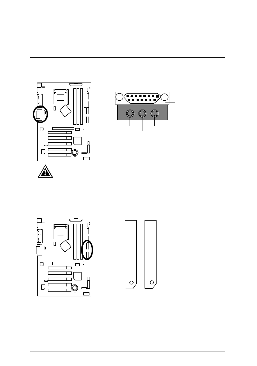
串列埠A/串列埠B/印表機並列埠插座
交流電
ATX
插入交流電源插座。
印表機並列埠插座
+5V 電壓
電源穩態訊號腳
電源開關控制腳
拔除,再將
11
1
定義
接地腳
電源插頭
A
串列埠 B 串列埠
請特別注意,本主機板支援二組標準的串列埠傳輸協定之週邊裝置、
及一組標準的並列傳輸協定之週邊裝置,您可以依據您的需求連接您
需要的裝置,如並列埠有印表機,串列埠有滑鼠、數據機等。
Page 22
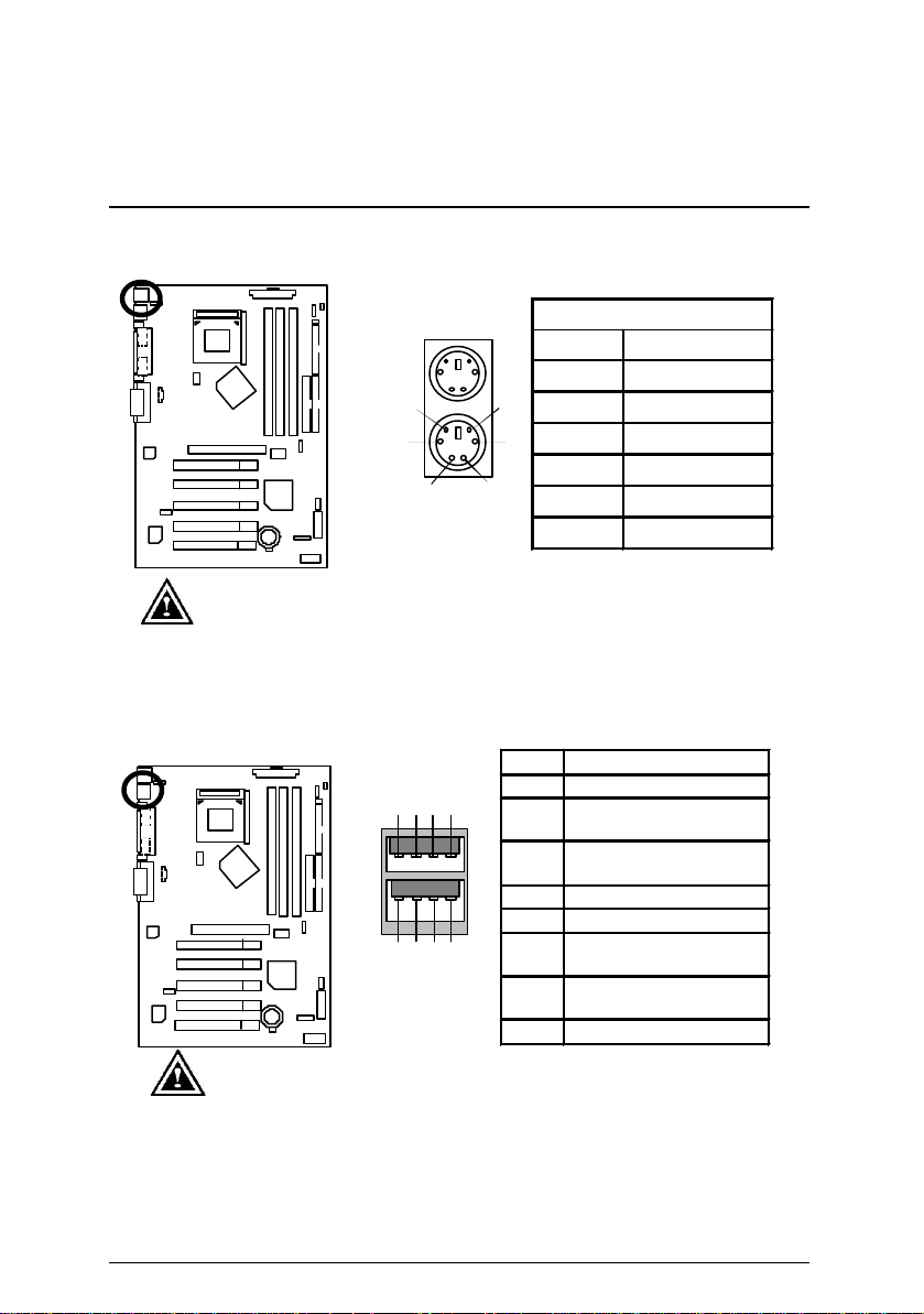
PS/2鍵盤及PS/2滑鼠插座
3
4
6
PS/2
PS/2
而且您也必須確認您的作業系統是否有支援此
插座及接腳設定說明
PS/2
PS/2 鍵盤
請特別注意,本主機板提供標準
腳。
USB1 : USB通用串列埠插座
1 2 3 4
請特別注意,當你要使用通用串列埠連接埠時,必須先確認您要使用
的週邊裝置為標準的
USB ZIP,USB
功能,或是需要另外再掛其他的驅動程式,如此才能正常工作,詳情
請參考
週邊裝置的使用手冊。
USB
喇叭等
USB
… .
滑鼠
2
8
6 5
7
介面,如:
PS/2 滑鼠/鍵盤
接腳
1
5
2
3 接地腳
1
4 電源
5 時脈
6 空腳
鍵盤介面及
接腳
1 USB 電源
第一組負極資料訊號
2
第一組正極資料訊號
3
4
5 USB 電源
第二組負極資料訊號
6
第二組正極資料訊號
7
8 接地腳
鍵盤,滑鼠,
USB
定義
訊號腳
空腳
滑鼠介面接
定義
(USB D0-)
(USB D0+)
接地腳
(USB D1-)
(USB D1+)
USB
掃瞄器,
Page 23
7ZXE 主機板
USB
USB
連接排線為選擇性的功能套件,可以聯
USB2 :前端通用串列埠插座
2
1
請特別注意, 前端
特別注意極性,而且前端
絡相關代理商購買。
接腳是有方向性的,所以安裝
Floppy Port 軟碟機插座
USB
10
9
接腳
1 電源
2
3 第三組負極資料訊號
4
5 第三組正極資料訊號
6
7
8 第四組負極資料訊號
9
10 電源
定義
接地腳
(USB D2-)
空腳
(USB D2+)
第四組正極資料訊號
(USB D3+)
空腳
(USB D3-)
接地腳
裝置時,要
紅色線為第一支腳
Page 24
遊戲搖桿控制埠及音源插座
埠,您在設定完成內建音效的驅動程式後,即可將喇叭輸出接腳
接在音源輸出端,而麥克風接腳可接在麥克風輸入端,至於音源
插座及接腳設定說明
遊戲搖桿
控制埠
音源輸出
請特別注意, 本主機板支援標準的音效輸入接腳及遊戲搖桿控制
輸入端可以接上如:光碟機,隨身聽及其他音源輸入接腳。
第一組IDE插座及第二組IDE插座
IDE 1 IDE 2
麥克風輸入
音源輸入
紅色線為第一支腳
Page 25
7ZXE 主機板
AGP或PCI
卡有散熱風扇接腳,我們即可以
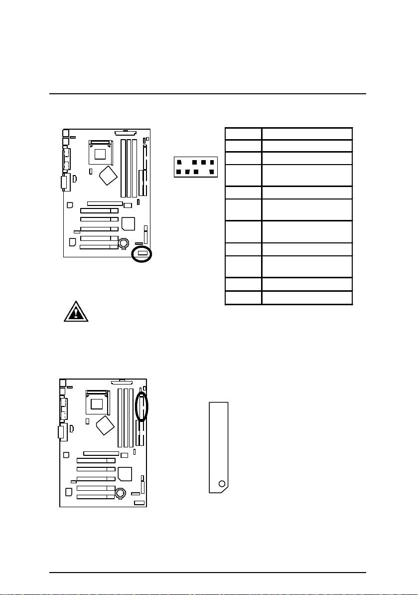
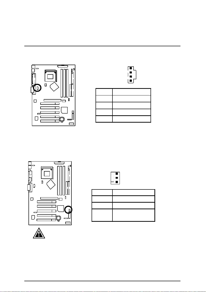
CD_IN : 光碟機音源接腳
1
接腳
1
2 接地腳
3
4 右聲道音源輸入
SYS_FAN : 系統散熱風扇電源接腳
接腳
1
2
3
請特別注意, 當有些
利用系統散熱風扇接腳,來協助相關裝置散熱。
定義
左聲道音源輸入
接地腳
1
定義
接地腳
電壓
+12V
偵測風扇轉速的
訊號腳
Page 26
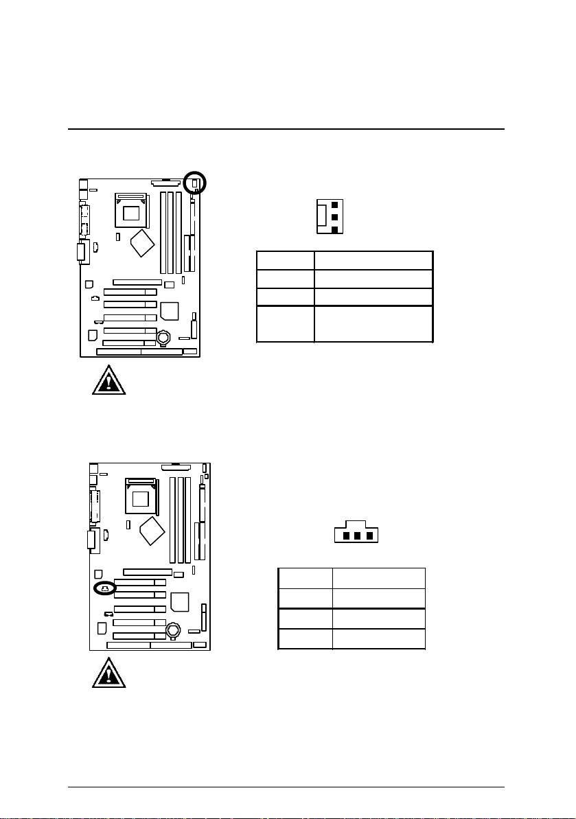
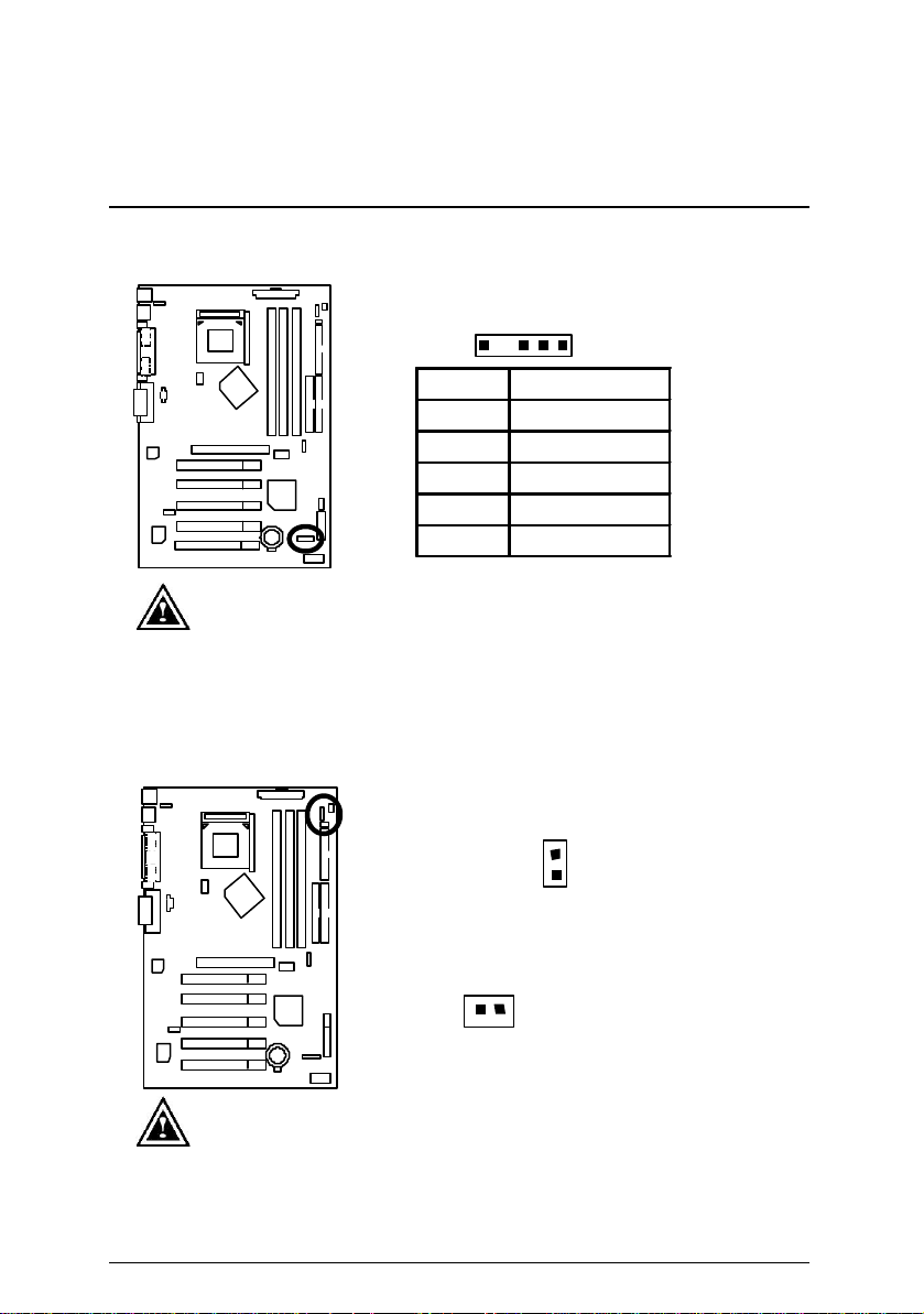
PWR_FAN : 電源散熱風扇電源接腳
ATX
Sony/Philip Digital Interface Format
/
飛利浦所制定
插座及接腳設定說明
1
接腳
接地腳
1
2 +12V
偵測風扇轉速的
3
訊號腳
請特別注意,一般我們建議
熱風扇,因為可以增加機殼內部散熱的速度進而減低機殼內的工
作溫度。
的主機板,至少安裝一台電源散
定義
電壓
SPDIF
1
接腳
1
2 數位音效輸出
3
請特別注意,
的數位介面格式,
者第三代音效編碼格式
意,使用此功能時,須確認您的音響系統具有數位輸入
功能。
輸出能夠提供數位音效給外接的喇叭或
SPDIF
解壓縮成杜比數位格式。請特別注
(AC-3)
定義
+5V
接地腳
為新力
電源
(SPDIF In)
Page 27
7ZXE 主機板
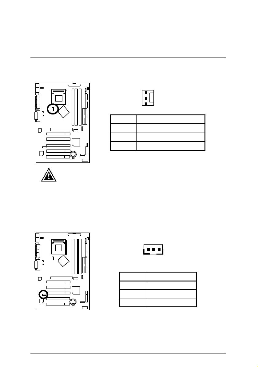
CPU_FAN : CPU散熱風扇電源接腳
1
請特別注意 ,當我們安裝處理器時要特別注意將散熱風扇安裝妥當,
不然您的處理器將處於不正常的工作環境,甚至會因為溫度過高,而
燒毀處理器。
此
CPU
散熱風扇電源插座, 提供最大電流為
WOL : 網路卡喚醒功能接腳
接腳
1
定義
接地腳
2 +12V 電壓
3 偵測風扇轉速的訊號腳
毫安培。
600
1
接腳
定義
1 +5V 待機電源
2
接地腳
3 訊號腳
Page 28
IR: 紅外線接腳
紅外線接腳是有方向性的,所以在安裝紅外線裝置
插座及接腳設定說明
1
接腳
1 +5V
定義
電源
2 空腳
3 紅外線接收腳
4 接地腳
5 紅外線傳輸腳
請特別注意,
時,要特別注意極性,而且紅外線裝置為選擇性的功能套件,可
以聯絡相關代理商購買。
STR_LED/ RAM LED : 外接STR指示燈連接腳及記憶體電源指
示燈
+
記憶體電源指示燈
外接
指示燈連接腳
STR
1
請特別注意,當記憶體電源指示燈亮起時,千萬不可以插拔記憶
體裝置,因為記憶體插槽內還有
或者其他不可預知的問題,請將
(AC110/220V)
拆下再做記憶體插拔的動作。
待機電源,可能會導致短路
3.3V
功能關閉或將交流電源
STR
Page 29
7ZXE 主機板
接腳定義說明
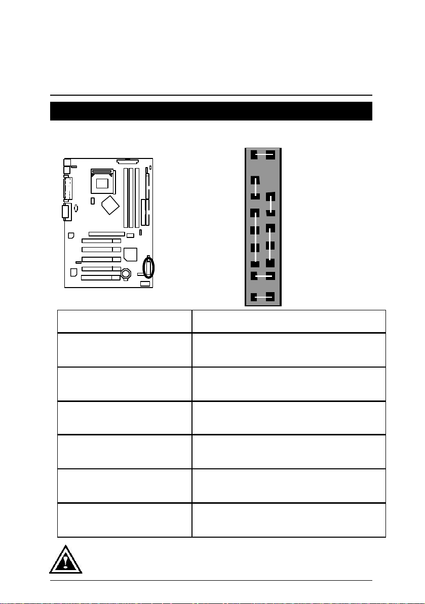
F-PANEL : For 2X11 接腳說明
GD
RE
S P K
1
PW
1
1
P−P−P+
HD
GN
1
GN (Green Switch)省電模式開關 Open: Normal Operation 開路:一般運作
Close: Entering Green Mode 短路:進入省電模式
GD (Green LED)省電模式指示燈 Pin 1: LED anode(+)省電指示燈正極
Pin 2: LED cathode(−)省電指示燈負極
M請注意正負極性
HD (IDE Hard Disk Active LED)
硬碟動作指示燈
SPKR (Speaker Connector)
喇叭接腳
RE (Reset Switch)系統重置開關 Open: Normal Operation 開路:一般運作
P+P−P−(Power LED)電源指示燈 Pin 1: LED anode(+) 電源指示燈正極
PW (Soft Power Connector)按鍵開關機 Open: Normal Operation 開路:一般運作
請特別注意,當您購買電腦機殼時,電腦機殼的控制面板有電源指示燈,喇叭,
系統重置開關,電源開關等,你可以依據上列表格的定義加上連接。
Pin 1: LED anode(+)硬碟指示燈正極
Pin 2: LED cathode(−)硬碟指示燈負極
M請注意正負極性
Pin 1: VCC(+) +5v 電源接腳
Pin 2- Pin 3: NC 空腳
Pin 4: Data(−) 訊號接腳
Close: Reset Hardware System 短路:強迫系統重置開 機
M無正負極性正反皆可使用
Pin 2: LED cathode(−)電源指示燈負極
Pin 3: LED cathode(−)電源指示燈負極
Close: Power On/Off 短路:開機/關機
M無正負極性正反皆可使用
Page 30

USB_ON :通用串列埠設備喚醒功能選擇接腳
1
請特別注意,如果您要使用通用串列埠設備喚醒功能時,必須將
BIOS
設成
"USB Dev Wakeup from
的設
插座及接腳設定說明
(
接腳
開啟通用串列埠設備喚醒功
短路
1-2
2-3短路
選項“
USB Dev Wakeup from S3~S5
啟動。
開機後當記憶體開始偵測計算時,按下
*(
設定,在
”POWER MANAGEMENT SETUP"內,
S3~S5: Enabled".
定儲存並離開
)
按下
"ESC"
能
關閉通用串列埠設備喚醒功
能(預設值
”開啟並將
鍵回到
"SAVE & EXIT SETUP"
STR 進階省電模式開關
1
開啟
接腳
.
短路 開啟進階省電模式
1-2
短路 關閉進階省電模式
2-3
(
1
關閉
預設值
)
定義
)
”USB_ON”及”STR_ON”
您將可進入
<Del>.
選擇
1
關閉
預設值
(
定義
預設值
)
開啟
)
BIOS
將變更
內選項
Page 31

7ZXE 主機板
如果電池有任何不正確的移除動作,
BAT1: 電池
+
警告
將會產生危險。
如果需要更換電池時請更換相同廠
牌、型號的電池。
有關電池規格及注意事項請參考電
池廠商之介紹。
Page 32

效能測試
AMD Athlo
1400MHz,AMD Duron
950MHz
1400MHz (266x5.25)
DRV-07CPU
Awadvs-04
CC Winstone 2001
Business Winstore 2001
效能測試
以下是 7ZXE 的測試數據,基本上這些測試數值僅供參考,因為不同的軟、硬體
配備都會影響測試結果,所以我們無法保證使用者自行測試的數據會與下列公佈
數值完全吻合。
TM
• CPU
• 記憶體
(128x1) MB RAM (PQI PC166 MP6828UMR-T6863 0205-A57)
n
• 快取記憶體 CPU 內建 384 KB 快取記憶體(Athlon)
• 顯示介面卡
CPU 內建 192 KB 快取記憶體(Duron)
GV-GF3000D
• 儲存裝置 內建 IDE 插座 (Quantum AS30000AT 30GB)
• 作業系統
• 驅動程式
Processor
WCPUID 2.8 Clock Frequency
SiSoft Sandra 20001
CPU/FPU Benchmark
CPU Multi-Media Benchmark
SPECviewperf 6.12
Winstone 2001
M 如果您想使您的系統獲得最高效能,詳細資料請參考第 45 頁.
Windows 2000 + SP2
顯示卡驅動程式使用1024 x 768 x 64k 色 75Hz解析度
AMD AthlonTM
Internal MHz
External MHz
Drivers Benchmark
Memory Benchmark
Pro CDRS-03
MedMCAD-01
Light-04
DX-06
1400.04 950.03
266.67 200.01
3905/1907 2649/1296
7885/8757 5348/5939
22119 20832
500/582 469/573
14.97 14.94
22.85 19.24
6.313 5.244
19.04 17.12
13.98 11.27
53.16 60.01
63.8 48.7
47.5 35.3
5285 4501
TM
950MHz (200x4.75)
處理器
AMD Duron
TM
Page 33

7ZXE 主機板
AC97
CODEC
AGP
晶片組功能方塊圖
AGPCLK (66MHz)
5 PCI
PCI (33MHz)
2X/4X
PCI Bus 33MHz
AMD-K7TM
System Bus 100/133MHz
VT8363A
VT82C
686B
Floppy
PS/2
AGPCLK (66MHz)
33MHz
14.318MHz
LPT
Game
Port
Port
CPUCLK (100/133MHz)
100/133MHz
COM Ports
3.3V SDRAM
HCLK (100/133MHz)
48MHz
4 USB Ports
ATA66/100
IDE Channels
AGPCLK (66MHz)
PCI (33MHz)
48MHz
14.318MHz
33MHz
ICS
94236AF
HCLK (100/133MHz)
AGPCLK (66MHz)
CPUCLK (100/133MHz)
Page 34

安裝 Suspend To RAM 功能
安裝 Suspend To RAM 功能
A.1 STR 功能簡介
STR 是一種 Windows 98/ME/2000 ACPI 下的暫停模式功能。 當恢復 STR 暫停模式,
系統能夠在幾秒鐘之內回復到進 STR(S3)之前的狀態, 這狀態是在系統進入暫停
模式之前就已經被存在記憶體內,當在 STR 暫停模式時,系統將會使用少量的能源
去維持 STR 功能重要的資料,並支援各種不同模式的喚醒功能。
A.2 STR 功能安裝
請依照下列步驟來完成 STR 安裝
步驟 1:
要使用 STR 功能, 系統必須在 Windows 98/ME/2000 ACPI 模式:
使用 Windows 98/ME/2000 光碟片安裝
A. 將 Windows ME/98/2000 光碟片放入光碟機中, 選擇開始, 並執行。
B. 依 Window 規定鍵入 “D:\Setup”, 按下 enter 或雙擊滑鼠兩下。
C. 當安裝完成後,從光碟機中移除光碟片,並重新啟動您的系統。
(我們假設光碟機的代號為 D:)
Page 35

7ZXE 主機板
步驟 2:
當使用
功能之前,您需要設定主機板上的
STR
”STR_EN” Jumper
開啟,如下圖所示
:
1
開啟
接腳
.
短路 開啟進階省電模式
1-2
短路 關閉進階省電模式
2-3
預設值
(
1
關閉
預設值
(
定義
)
)
步驟 3:
當系統開機開始計算記憶體時, 按下<Del>。您將會進入 BIOS 設定畫面,選
擇”POWER MANAGEMENT SETUP”,並選”ACPI Sleep Type : S3/STR”。請務必記得要按
下”ESC”並選擇”SAVE & EXIT SETUP”來儲存設定。
恭喜您!!您已經順利的完成了 STR 的功能安裝。
Page 36

安裝 Suspend To RAM 功能
A.3 如何讓您的系統進入 STR 模式? (For Example:Windows ME)
有兩種方式來完成:
1.選擇”關閉 Windows”中的” 待機” 選項
A. 在 Windows ME 功能列選擇”開始”並選”關機”
B. 選擇”待機”並按下”確定”。
Page 37

7ZXE 主機板
2.定義系統在按下“電源開關”按鈕是進入 STR 模式:
A. 用滑鼠雙擊”我的電腦”中的”控制台” 。
B. 用滑鼠雙擊”電源管理”選項。
Page 38

安裝 Suspend To RAM 功能
C. 選擇”進階”並選”待機”模式.
D. 在完成設定後重新啟動你的系統.當您想要進入 STR 省電模式時, 只要按
下”電源開關”按鈕即可。
A.4 如何恢復到 STR 省電模式?
有 4 種方式可”喚醒”系統:
1. 按下”電源開關”按鈕。
2. 使用”定時開機”功能。
3. 使用”網路卡開機”功能。
4. 使用”USB 裝置喚醒”功能。
Page 39

7ZXE 主機板
A.5 注意事項:
1.為了要使用正確的 STR 功能,一些硬體及軟體的需求是必須符合的:
A. 您的 ATX 電源供應器必須要是 ATX 2.01 的規格(供應超過 720 毫安培 5V
Stand-By 電流)
B. SDRAM 必須是符合 PC-100/PC-133 規格。
2. “STR_LED” Jumper 是STR 指示燈的連接頭.當系統進入 STR 省電模式時, STR 指示
燈將會亮起.
+
記憶體電源指示燈
外接
指示燈連接腳
STR
1
請特別注意,當記憶體電源指示燈亮起時,千萬不可以插拔記憶
體裝置,因為記憶體插槽內還有
或者其他不可預知的問題,請將
(AC110/220V)
拆下再做記憶體插拔的動作。
待機電源,可能會導致短路
3.3V
功能關閉或將交流電源
STR
Page 40

Q-Flash BIOS 燒錄工具程式功能介紹
Q-Flash BIOS 燒錄工具程式功能介紹
A.
什麼是
Q-Flash BIOS
技嘉科技帶您進入 BIOS 更新技術之新領域,跳脫傳統煩瑣的燒錄 BIOS 步驟
及過程..提供一個簡單方便的更新及備份工具,不受任何作業程式及應用程
式之限制.
在開機時即可做 BIOS 的更新及備份工作.
B.
如何使用
Q- Flash BIOS
a. 進入BIOS畫面, 按 <F8>
STANDARD CMOS SETUP INTEGRATED PERIPHERALS
BIOS FEATURES SETUP HARDWARE MONITOR & MISC SETUP
CHIPSET FEATURES SETUP SUPERVISOR PASSWORD
POWER MANAGEMENT SETUP USER PASSWORD
PNP / PCI CONFIGURATION IDE HDD AUTO DETECTION
LOAD FAIL -SAFE DEFAULTS SAVE & EXIT SETUP
LOAD OPTIMIZED DEFAULTS EXIT WITHOUT SAVING
ESC: Quit ↑↓ ←→ : Select Item (Shift)F2 : Change Color F5: Old Values
F6: Fail-Safe Values F7: Optimized Values F8 : Flash Utility F10:Save & Exit
燒錄工具程式
燒錄工具程式
AMIBIOS SIMPLE SETUP UTILITY – VERSION 1.24f
(C) 1999 American Megatrends, Inc. All Rights Reserved
Enter BIOS Flash Utility (Y/N)? Y
?
?
Time, Date , Hard Disk Type…
b. AMI Q-Flash BIOS燒錄工具程式畫面
AMI BIOS Flash Utility V1.02
Boot From……………………….. Main BIOS
Main ROM Type………………… HYUNDAI HY29F002T
Load BIOS from Floppy
Enter : Run ↑↓ : Move ESC : Res et F10 : Power Off
Page 41

7ZXE 主機板
BIOS
<Enter>鍵.
c.將存有BIOS檔案的磁碟片放入A:磁碟機,然後按<Enter>鍵.
d.在文字框”Load”後輸入BIOS 檔名,然後按<Enter>鍵
Load XXX.XX
XXX.XX 表示 BIOS 的檔名.
Load XXX.XX
Are you sure to COPY BIOS?
[Enter] to Continue Or [Esc] to abort..
若您確定要開始燒錄
程式,請按下
否則按<Esc>離開此程式.
Load XXX.XX
!! COPY BIOS Completed –Pass !!
Please press any key to continue
恭喜您!!您已經順利成功的燒錄 BIOS。
Page 42

@BIOS™功能介紹
@BIOS
TM
功能介紹
技嘉科技
@BIOSTM
視窗版
BIOS
更新軟體
技嘉科技繼視窗超頻軟體 EasyTuneIIITM之後再度推出另一石破天
,為擺脫傳統須在
驚
技嘉科技@BIOSTM為一提供使用者在視窗模式下更新 BIOS 的軟
體,使用者可透過@BIOSTM友善的使用者界面,簡易的操作模式,從此
更新、儲存BIOS不再是電腦高手的專利,輕輕鬆鬆完成不可能的任務,
更炫的是使用者可透過@BIOSTM與 Internet 連結,選取距離最近的 BIOS
伺服器並下載最新的 BIOS 更新,所有過程皆在 Windows模式下完成,從
此不再害怕更新 BIOS !
相信如此重量級的工具程式應是大家引領期盼很久了吧!試試技嘉
科技@BIOSTM從此更新 BIOS 不再驚聲尖叫!
模式下更新
DOS
BIOS之Windows
版軟體!
Page 43

7ZXE 主機板
EasyTuneIIITM功能介紹
技嘉科技EasyTuneIII TM視窗超頻軟體
技嘉科技全新推出視窗超頻軟體 EasyTuneIII
覆超頻科技!
有了技嘉科技視窗超頻軟體 EasyTuneIIITM後,從此超頻不須更改
BIOS 上之設定,更不須膽戰心驚地調整主機板上的任何 Jumpers 或
Switches,絢麗、簡單的使用者界面更提供了超頻的親切性,在簡易模式
下,僅需按下“自動最佳化“一鍵,EasyTuneIIITM便能自動在短短數秒
鐘之內找出最佳化值,並直接超頻,無須其他設定便能達軟體建議之最
佳化狀態,即使是從未超頻的生手也能輕鬆超頻。除此之外, EasyTune
IIITM更提供了進階模式,符合進階使用者的需求,可自行更改 CPU 的外
頻,找出自己系統的最佳化設定,最重要的是不須重開機即可生效。
經由以上簡單地介紹,您是否已有躍躍欲試而想趕快拿到
EasyTuneIII
它!如須更多資訊,請至 http://www.gigabyte.com.tw
ø 備註:如果您需要最新版的 EasyTuneIIITM 工具程式,請至網站下載。
TM
視窗超頻軟體來玩玩的衝動呢?試試看!相信你會愛上
TM
,一改以往超頻方式,顛
Page 44

BIOS 組態設定
$ BIOS 組態設定目錄
主畫面功能 P.38
標準 CMOS 設定
BIOS 功能設定
晶片組的特性設定
省電功能設定
隨插即用與 PCI 組態設定
載入 Fail-Safe 預設值
載入 Optimized 預設值
整合週邊設定
硬體監視設定
設定管理者(Supervisor)/使用者(User)密碼
自動偵測 IDE 硬碟
離開 SETUP 並儲存設定結果
離開 SETUP 但不儲存設定結果 P.66
Page
P.40
P.43
P.45
P.49
P.52
P.55
P.56
P.57
P.62
P.63
P.64
P.65
Page 45

7ZXE 主機板
BIOS 組態設定
基本上主機板所附 AMI BIOS 便包含了CMOS SETUP 程式,以供使用者自行依照需
求,設定不同的數據,使電腦正常工作,或執行特定的功能.
CMOS SETUP會將各項數據儲存於主機板上內建的CMOS RAM中,當電源關閉時,
則由主機板上的鋰電池繼續供應CMOS RAM所需電力。
當電源開啟之後,BIOS 開始進行 POST(Power On Self Test開機自我測試)時,按
下<Del>鍵便可進入 AMI BIOS 的 CMOS SETUP 主畫面中。
操作按鍵說明
á(向上鍵) 移到上一個項目
â(向下鍵) 移到下一個項目
ß(向左鍵) 移到左邊的項目
à(向右鍵) 移到右邊的項目
Esc 鍵 回到主畫面,或從主畫面中結束 SETUP 程式
Page Up鍵 改變設定狀態,或增加欄位中之數值內容
Page Down鍵 改變設定狀態,或減少欄位中之數值內容
F1 功能鍵 可顯示目前設定項目的相關說明
F2 功能鍵 功能保留
F3 功能鍵 功能保留
F4 功能鍵 功能保留
F5 功能鍵 可載入該畫面原先所有項目設定
F6 功能鍵 可載入該畫面之 Fail-Safe 預設設定
F7 功能鍵 可載入該畫面之 Optimized 預設設定
F8 功能鍵 功能保留
F9 功能鍵 功能保留
F10 功能鍵 儲存設定並離開 CMOS SETUP 程式
如何使用輔助說明
主畫面的輔助說明
當您在SETUP主畫面時,隨著選項的移動,底下便跟著顯示︰目前被選到的SETUP
項目的主要設定內容。
Page 46

BIOS 組態設定
設定畫面的輔助說明
當您在設定各個欄位的內容時,只要按下<F1>,便可得到該欄位的設定預設值
及所有可以的設定值,如 BIOS 預設值或CMOS SETUP 預設值,若欲跳離輔助說明
視窗,只須按<Esc>鍵即可。
主畫面功能(For Example BIOS Version :7ZXE.F2e)
當您進入CMOS SETUP設定畫面時,便可看到如下之主畫面,從主畫面中可以讓你
選擇各種不同之設定選單,你可以用上下左右鍵來選擇你要設定之選項並按Enter
進入子選單.
AMIBIOS SIMPLE SETUP UTILITY – VERSION 1.24g
(C) 1999 American Megatrends, Inc. All Rights Reserved
STANDARD CMOS SETUP INTEGRATED PERIPHERALS
BIOS FEATURES SETUP HARDWARE MONITOR & MISC SETUP
CHIPSET FEATURES SETUP SUPERVISOR PASSWORD
POWER MANAGEMENT SETUP USER PASSWORD
PNP / PCI CONFIGURATION IDE HDD AUTO DETECTION
LOAD FAIL -SAFE DEFAULTS SAVE & EXIT SETUP
LOAD OPTIMIZED DEFAULTS EXIT WITHOUT SAVING
ESC: Quit ↑↓ ←→ : Select Item (Shift)F2 : Change Color F5: Old Values
F6: Fail-Safe Valu es F7: Optimized Values F8 : Flash Utility F10:Save & Exit
Time, Date , Hard Disk Type…
圖 1: 主畫面功能
• Standard CMOS Setup (標準 CMOS 設定)
設定日期、時間、軟硬碟規格、及顯示器種類。
• BIOS Features Setup (BIOS 功能設定)
設定 BIOS 提供的特殊功能,例如病毒警告、開機磁碟優先程序、磁碟代號
交換....等。
Page 47

7ZXE 主機板
• Chipset Features Setup (晶片組特性設定)
設定主機板採用的晶片組相關運作參數,例如「DRAM Timing」、「 ISA
Clock」....等。
• Power Management Setup (省電功能設定)
設定 CPU、硬碟、GREEN 螢幕等裝置的省電功能運作方式。
• PNP/PCI Configuration (即插即用與 PCI 組態設定)
設定 ISA之 PnP 即插即用介面以及 PCI介面的相關參數。
• Load FAIL-SAFE Defaults (載入 Fail-Safe 預設值)
執行此功能可載入 FAIL-SAFE 的 CMOS 設定預設值,此設定是比較保守,
但較能進入開機狀態的設定值。
• Load OPTIMIZED Defaults (載入 Optimized 預設值)
執行此功能可載入 Optimized 的 CMOS 設定預設值,此設定是較能發揮主機
板速度的設定。
• Integrated Peripherals (內建整合週邊設定)
在此設定畫面包括所有週邊設備的的設定。如 COM Port 使用的 IRQ 位
址,LPT Port 使用的模式 Normal、EPP 或 ECP 以及 IDE 介面使用何種
PIO Mode 等裝置之設定。
• Hardware Monitor & MISC Setup (硬體監視設定)
自動偵測風扇及系統溫度功能。
• Supervisor Password (管理者的密碼)
設定一個密碼,並適用於進入系統或進入 SETUP 修改 CMOS 設定。
• User Password (使用者的密碼)
設定一個密碼,並適用於開機使用 PC 及進入 BIOS 修改設定 。
• IDE HDD Auto Detection (自動偵測 IDE 硬碟)
自動偵測 IDE 的參數設定,並可選擇寫入 CMOS(記得要存檔)。
• Save & Exit Setup (儲存並結束)
儲存所有設定結果並離開 SETUP 程式,此時 BIOS 會重新開機,以便使用
新的設定值,按<F10>亦可執行本選項。
• Exit Without Saving (離開 CMOS 不儲存設定)
不儲存修改結果,保持舊有設定並重新開機,按 <ESC>亦可直接執行本選項。
Page 48

BIOS 組態設定
標準CMOS設定
在STANDARD CMOS SETUP中,主要是為了設定IDE硬碟的種類,以順利開機,除
此之外,還有日期、時間、軟碟規格、及顯示卡的種類可以設定
AMIBIOS SETUP – STANDARD CMOS SETUP
Date (mm/dd/yyyy) : Thu Feb 17, 2000
Time (hh/mm/ss) : 14:44:35
TYPE SIZE CYLS HEAD PRECOMP LANDZ SECTOR MODE
Pri Master : Auto
Pri Slave : Auto
Sec Master : Auto
Sec Slave : Auto
Floppy Drive A : 1.44 MB 3½
Floppy Drive B : Not Installed Other Memory : 384 Kb
Extended Memory : 63 Mb
Boot Sector Virus Pro tection : Disabled Total Memory : 64 Mb
Month : Jan – Dec ESC : Exit
Day : 01– 31 ↑↓ : Select Item
Year : 19 90 – 2099 PU / PD / + / – :Modify
(Shift) F2 : Color
( C ) 1999 American Megatrends, Inc. All Rights Reserved
Base Memory : 640 Kb
圖 2: 標準 CMOS 設定
• Date(mm:dd:yy) (日期設定)
即設定電腦中的日期,格式為「星期,月/日/年」,各欄位設定範圍如下表示:
Week
Month
Day
Year
由目前設定的「月/日/年」自萬年曆公式推算出今天為星期幾,
此欄位無法自行修改。
月。
1到12
1到28/29/30/31
1990到2099
日,視月份而定。
年。
• Time(hh:mm:ss) (時間設定)
即設定電腦中的時間是以 24 小時為計算單位,格式為「時:分:秒」舉例而
言,下午一點表示方式為 13 : 00 : 00。當電腦關機後,RTC 功能會繼續執行,
並由主機板的電池供應所需電力。
Page 49

7ZXE 主機板
• Primary Master, Slave / Secondary Master, Slave
(第一組硬碟/第二組硬碟參數設定)
設定第一、二組 IDE 硬碟參數規格,設定方式有兩種,建議的是設定方式是
採方式 1,但經常更換 IDE 硬碟的使用者則可採方式 2,省去每次換硬碟都要
重新設定 CMOS 的麻煩。
方式 1:設成 User TYPE,自行輸入下列相關參數,即 CYLS、HEADS、SECTORS、
MODE,以便順利使用硬碟。
方式2:設定AUTO,將TYPE及MODE皆設定AUTO,讓BIOS在POST過程中,自
動測試IDE裝置的各項參數直接採用。
CYLS. Number of cylinders.(磁柱的數量)
HEADS number of heads.(磁頭的數量)
PRECOMP write precomp.
LANDZONE Landing zone.
SECTORS number of sectors(磁區的數量).
如果沒有裝設硬碟,請選擇”NONE”後按<Enter>
• Floppy Drive A / Drive B
可設定的項目如下表示:
None 沒有安裝磁碟機。
360K, 5.25 in.
1.2M, 5.25 in.
720K, 3.5 in.
1.44M, 3.5 in.
2.88M, 3.5 in.
吋磁碟機,
5.25
吋磁碟機,
5.25
吋半磁碟機,
3
吋半磁碟機,
3
吋半磁碟機,
3
360KB
1.2MB
720KB
1.44MB
2.88MB
容量。
容量。
容量。
容量。
容量。
• Boot Sector Virus Protection (病毒警告)
Enabled
Disabled
啟動此功能,當硬碟的啟動磁區或分割區被改寫時,會發出
警告訊息,由使用者決定是否要被寫入。
不啟動此功能。(預設值
)
Page 50

BIOS 組態設定
• Memory (記憶體容量顯示)
目前主機板所安裝的記憶體皆由 BIOS 之POST(Power On Self Test)自動偵測,
並顯示於 STANDARD CMOS SETUP 右下方。
Base Memory:傳統記憶體容量
PC 一般會保留 640KB 容量做為 MS-DOS 作業系統的記憶體使用空間。
Extended Memory:延伸記憶體容量
可做為延伸記憶體的容量有多少,一般是總安裝容量扣除掉 Base
及 Other Memory 之後的容量,如果數值不對,可能是有 Memory Module
沒安裝好,請仔細檢查。
Other Memory:其它記憶體容量
通常是指 BIOS 從記憶體容量中,取 384KB 容量,做為 BIOS Shadow
功能的用途(Shadow RAM)。主要是在開機時,BIOS 將一些裝置的驅
動程式 Copy 到 DRAM 上面,使 BIOS 的執行速度提昇,有助 PC 整體
的效益。
Page 51

7ZXE 主機板
BIOS功能設定
AMIBIOS SETUP – BIOS FEATURES SETUP
( C ) 1999 American Megatrends, Inc. All Rights Reserved
1st Boot Device Floppy
2nd Boot Device IDE-0
3rd Boot Device CDROM
S.M.A.R.T. for Hard Disks Disabled
BootUp Num -Lock On
Floppy Drive Seek Enabled
Password Check Setup
F1 : Help PU/PD+/-/ : Modify
F5 : Old Values (Shift)F2:Color
F6 : Load Fail-Safe F8:Flash Utility
F7 : Load Optimized
ESC: Quit
圖 3: BIOS 功能設定
↑↓← →
: Select Item
1st / 2nd / 3rd Boot Device (
•
Floppy
ZIP A: /LS 120
CDROM
SCSI
NETWORK
IDE-0~IDE-3
Disabled
ATAPI ZIP C:
第一/二/三優先開機裝置
由軟碟機為第一優先的開機裝置。
由 ZIP A:/ LS-120 為第一優先的開機裝置。
由光碟機為第一優先的開機裝置。
由 SCSI 裝置為第一優先的開機裝置。
由 PCI網路卡為第一優先的開機裝置。
由硬碟機為第一優先的開機裝置。
關閉此功能。
由 ATAPI ZIP C:為第一優先的開機裝置。
• S.M.A.R.T. for Hard Disks(硬碟自我檢測功能)
Enabled 啟動硬碟 S.M.A.R.T. 的功能。
Disabled 關閉硬碟 S.M.A.R.T. 的功能。(預設值)
• Boot Up Num-Lock(起始時數字鍵鎖定狀態)
On
Off
開機後將數字區設成數字鍵功能。(預設值
開機後將數字區設成方向鍵功能。
)
)
Page 52

BIOS 組態設定
• Floppy Drive Seek (開機時測試軟碟)
設定在 PC 開機時,POST程式需不需要對 FLOPPY 做一次讀寫頭定位測試。
可設定的項目為:
Enabled
Disabled
要對
Floppy做Seek
不必對
Floppy做Seek
測試。(預設值
測試。
)
• Password Check (檢查密碼方式)
Always
Setup
無論是開機或進入
只有在進入
CMOS SETUP
CMOS SETUP
均要輸入密碼。
時才要求輸入密碼。(預設值
)
M欲取消密碼之設定時,只要於 SETUP 內重新設定密碼時,不要按任何鍵,
直接按<Enter>使密碼成為空白,即可取消密碼的設定。
詳細資料請參考第 63 頁。
Page 53

7ZXE 主機板
晶片組的特性設定
我們不建議您任意改變此項預設值,除非您真的需要去更改設定。
AMIBIOS SETUP – CHIPSET FEATURES SETUP
( C ) 1999 American Megatrends, Inc. All Rights Reserved
*********DRAM Timing*** SDRAM Command Drive 24 mA
Top Performance Disabled Memory Address Drive 24 mA
DRAM Frequency 100MHz CAS# Drive 12 mA
SDRAM CAS# Lat ency 3 RAS# Drive 24 mA
AGP Fast Write Disabled
AGP Mode 4X
AGP Comp. Driving Auto
Manual AGP Comp. Driving DB
AGP Aperture Size 64MB
PCI Delay Transaction Enabled
USB Controller All USB Port
USB Legacy Support Disabled
USB Port 64/ 60 Emulation Disabled
BIOS Flash Protection Auto
DRAM Drive Strength Auto
MD Bus Strength High F1 : Help PU/PD+/-/ : Modify
CAS Bus Strength High F5 :Old Values (Shift)F2:Color
Delay DRAM Read Latch 1.0ns F6 : Load Fail-Safe F8: Flash Utility
Memory Data Drive 8 mA F7 : Load Optimized
ESC: Quit
↑↓←→
: Select Item
圖 4: 晶片組的特性設定
• Top Performance (最高效能)
如果您想使您的系統獲得最高效能,請將“Top Performance”設定為
“Enabled”。
Disabled 關閉此功能。(預設值)
Enabled 開啟 Top Performance功能。
• DRAM Frequency
Auto 由 BIOS 自動去設定 DRAM Frequency。
100MHz 設定 DRAM Frequency 為 100MHz。(預設值)
133MHz 設定 DRAM Frequency 為 133MHz。
• SDRAM CAS# Latency (SDRAM CAS 延遲時間)
Auto 設定 SDRAM CAS# Latency 為 Auto。
3 使用較慢 SDRAM DIMM module。(預設值)
2 使用較快 SDRAM DIMM module。
Page 54

• AGP Fast Write
Disabled 關閉此功能。(預設值)
Enabled 啟動 AGP Fast Write 功能。
• AGP Mode (AGP 模式)
4X 設定 AGP 模式為 4X。(預設值)
1X 設定 AGP 模式為 1X。
2X 設定 AGP 模式為 2X。
• AGP Comp. Driving
Auto 設定 AGP Comp. Driving 為 Auto。 (預設值)
Manual 設定 AGP Comp. Driving 為 Manual。
如果將 AGP Comp. Driving 設定為 Manual:
Manual AGP Comp. Driving: 00~FF
• AGP Aperture Size
4MB 設定 AGP Aperture Size為 4 MB。
8MB 設定 AGP Aperture Size為 8 MB。
16MB 設定 AGP Aperture Size為 16 MB。
32MB 設定 AGP Aperture Size為 32 MB。
64MB 設定 AGP Aperture Size為 64 MB。(預設值)
128MB 設定 AGP Aperture Size為 128 MB。
256MB 設定 AGP Aperture Size為 256 MB
BIOS 組態設定
• PCI Delay Transaction
Enabled 啟動 Delay Transaction。 (預設值)
Disabled 關閉此功能。
• USB Controller (通用序列匯流排功能)
Disabled 不啟動 USB 功能.
USB Port 0&1
USB Port 2&3
All USB Port
啟動 USB Port 0 & 1.
啟動 USB Port 2 & 3.
啟動所有 USB Port. (預設值)
Page 55

7ZXE 主機板
• USB Legacy Support
當啟動 USB 功能,USB 的支援形態將可被設定。
Keyboard/FDD 支援 USB 鍵盤/ 磁碟機。
KB/Mouse/FDD 支援 USB 鍵盤/ USB 滑鼠 /磁碟機。
Disabled 關閉此功能。(預設值)
• USB Port 64/60 Emulation
當您要在NT的作業系統環境下使用USB 滑鼠時,必須將“USB Legacy Support”
選項設為 KB/Mouse/FDD 及“USB Port 64/60 Emulation”選項設為Enabled,USB
滑鼠才可以動作。
Enabled 啟動在 NT的作業系統環境下使用 USB 滑鼠的功能。
Disabled 關閉此功能。(預設值)
• BIOS Flash Protection (BIOS 防寫保護)
Enabled 在開機過程中時,不會更新 DMI/ESCD。開機完後只能用
Auto 在開機過程中時,會更新DMI/ESCD。使用本公司的工具
本公司的工具更新 BIOS。
程式更新 BIOS、DMI/ESCD 的時候,系統會自動開啟
FLASH 寫入權限 (預設值)
• DRAM Drive Strength
Auto 自動偵測 DRAM Drive Strength。(預設值)
Manual 手動設定 DRAM Drive Strength。
當 DRAM Drive Strength 設定為 Manual 時,你將可針對以下選項做調整。
• MD Bus Strength
High 設定 MD Bus Strength 為 High。(預設值)
Low 設定 MD Bus Strength 為 Low。
• CAS Bus Strength
High 設定 CAS Bus Strength 為 High。(預設值)
Low 設定 CAS Bus Strength 為 Low 。
• Delay DRAM Read Latch
1.0ns 設定 DRAM Read Latch Delay 為 1.0ns。(預設值)
1.5ns 設定 DRAM Read Latch Delay 為 1.5ns。
0.5ns 設定 DRAM Read Latch Delay 為 0.5ns。
No delay 設定 DRAM Read Latch 為 No delay。
Page 56

• Memory Data Drive
6 mA 設定 Memory Data Drive 為 6 mA。
8 mA 設定 Memory Data Drive 為 8 mA。(預設值)
• SDRAM Command Drive
16 mA 設定 SDRAM Command Drive 為 16 mA。
24 mA 設定 SDRAM Command Drive 為 24 mA。(預設值)
• Memory Address Drive
16 mA 設定 Memory Address Drive 為 16 mA。
24 mA 設定 Memory Address Drive 為 24 mA。(預設值)
• CAS# Drive
8 mA 設定 CAS# Drive為 8 mA。
12 mA 設定 CAS# Drive為 12 mA。(預設值)
• RAS# Drive
16 mA 設定 RAS# Drive為 16 mA。
24 mA 設定 RAS# Drive為 24 mA。(預設值)
BIOS 組態設定
Page 57

7ZXE 主機板
省電功能設定
AMIBIOS SETUP – POWER MANAGEMENT SETUP
( C ) 1999 American Megatrends, Inc. All Rights Reserved
ACPI Sleep Type S1/POS RTC Alarm Hour 00
USB Dev Wakeup from S3~S5 Disabled RTC Alarm Minute 00
Suspend Time Out(Minute) Disabled RTC Alarm Second 00
Display Activity Ignore
IRQ3 Monitor
IRQ4 Monitor
IRQ5 Ignore
IRQ7 Monitor
IRQ9 Ignore
IRQ10 Ignore
IRQ11 Ignore
IRQ13 Ignore
IRQ14
IRQ15 Ignore
Soft-Off by Power Button
System after AC Back Soft-Off
Resume on Ring/LAN Enabled F1 : Help PU/PD+/-/ : Modify
PME Event Wake Up Enabled F5 :Old Values (Shift)F2:Color
Resume On RTC Alarm Disabled F6 : Load Fail-Safe F8 : Flash Utility
RTC Alarm Date
Monitor
Instant -Off
Every Day
ESC : Quit
F7 : Load Optimized
↑↓→ ←
: Select Item
圖 5: 省電功能設定
• ACPI Sleep Type
S1/POS 設定 ACPI Sleep type 為 S1. (預設值)
S3/STR 設定 ACPI Sleep type 為 S3.
• USB Dev Wakeup From S3~S5
(由省電模式(S3)~關機模式(S5)使用 USB 裝置喚醒系統)
Disabled 關閉此功能. (預設值)
Enabled 啟動此功能.
Page 58

• Suspend Time Out (Minute)
Disabled 不設定此功能。(預設值)
1 設定電腦離線 1 分鐘後進入 Suspend 省電模式。
2 設定電腦離線 2 分鐘後進入 Suspend 省電模式。
4 設定電腦離線 4 分鐘後進入 Suspend 省電模式。
8 設定電腦離線 8 分鐘後進入 Suspend 省電模式。
10 設定電腦離線 10 分鐘後進入 Suspend 省電模式。
20 設定電腦離線 20 分鐘後進入 Suspend 省電模式。
30 設定電腦離線 30 分鐘後進入 Suspend 省電模式。
40 設定電腦離線 40 分鐘後進入 Suspend 省電模式。
50 設定電腦離線 50 分鐘後進入 Suspend 省電模式。
60 設定電腦離線 60 分鐘後進入 Suspend 省電模式。
• Display Activity
Ignore 忽略螢幕監控功能。(預設值)
Monitor 啟動螢幕監控功能。
• IRQ 3~IRQ15
Ignore 忽略 IRQ3 ~IRQ15。
Monitor 監控 IRQ3~IRQ15。
• Soft-off by Power Button (關機方式)
BIOS 組態設定
Instant-off 按一下 Soft-Off 開關便直接關機。(預設值)
Delay 4 Sec. 須按住 Soft-Off 開關 4 秒後才關機。
• System after AC Back(電源回復時的系統狀態)
Memory 電源回復時,恢復系統斷電前狀態。
Soft-Off 需按 Soft PWR button 才能重新啟動系統。(預設值)
Full-On 電源回復時,立刻啟動系統。
• Resume On Ring / LAN(數據機開機/網路開機)
Disabled 不啟動數據機開機/網路開機.
Enabled 啟動數據機開機/網路開機. (預設值)
Page 59

7ZXE 主機板
• PME Event Wake Up (電源管理事件喚醒功能)
Disabled 不啟動電源管理事件喚醒功能。
Enabled 啟動電源管理事件喚醒功能。(預設值)
• Resume On RTC Alarm (定時開機)
您可以將“Resume On RTC Alarm”這個選項設定為Enabled並且輸入開機的時
間。
Disabled 不啟動此功能。(預設值)
Enabled 啟動定時開機功能。
若啟動定時開機功能,則可設定以下時間:
RTC Alarm Date:
RTC Alarm Hour: 0~23
RTC Alarm Minute: 0~59
RTC Alarm Second: 0~59
Every Day,1~31
Page 60

BIOS 組態設定
隨插即用與PCI組態設定
AMIBIOS SETUP – PNP / PCI CONFIGURATION
( C ) 1999 American Megatrends, Inc. All Rights Reserved
PnP OS Installed No
Reset Configuration Data
VGA Boot from AGP
PCI AGP Palette Snoop Disabled
PCI Slot 1/5 IRQ Priority Auto
PCI Slot 2 IRQ Priority Auto
PCI Slot 3 IRQ Priority
PCI Slot 4 IRQ Priority Auto
IRQ 3 PCI/PnP
IRQ 4 PCI/PnP
IRQ 5 PCI/PnP
IRQ 7 PCI/PnP
IRQ 9 PCI/PnP
IRQ 10 PCI/PnP
IRQ 11 PCI/PnP F1 : Help PU/PD+/-/ : Modify
IRQ 14 PCI/PnP F5 :Old Values (Shift)F2:Color
IRQ 15 PCI/PnP F6 : Load Fail-Safe F8 : Flash Utility
F7 : Load Optimized
No
Auto
ESC: Quit ↑↓ ←→: Select Item
圖 6: 隨插即用與PCI組態設定
• PnP OS Installed (是否安裝 PnP 作業系統)
Yes
No
啟動 O/S 隨插既用(PnP)的功能。
關閉 O/S 隨插既用(PnP)的功能。(預設值)
• Reset Configuration Data (清除組態資料)
指示 BIOS 將所有 PnP 等相關組態清除,以便寫入或恢復部份預設值。
Yes
No
執行 Reset Configuration Data 動作。
不執行 Reset Configuration Data。(預設值)
• VGA Boot From
AGP 設定 VGA Boot From 為 AGP。(預設值)
PCI 設定 VGA Boot From 為 PCI。
Page 61

7ZXE 主機板
• PCI/VGA Palette Snoop (顏色校正)
當您安裝 MPEG 後,若發現顯示顏色異常,可試設定此值為 Enabled,以校正
顏色輸出。
Enabled
Disabled
要作顏色校正動作。
不需要作顏色校正動作。(預設值
)
• PCI Slot 1,5 IRQ Priority
Auto 系統會自動保留可用的 IRQ 給 PCI slot 1 及 5 裝置使用。
(預設值)
3 如果沒有將 IRQ3給 ISA 裝置使用,那麼系統會保留給 PCI
slot 1 及 5 裝置使用。
4 如果沒有將 IRQ4 給 ISA 裝置使用,那麼系統會保留給 PCI
slot 1 及 5 裝置使用。
5 如果沒有將 IRQ5 給 ISA 裝置使用,那麼系統會保留給 PCI
slot 1 及 5 裝置使用。
7 如果沒有將 IRQ7 給 ISA 裝置使用,那麼系統會保留給 PCI
slot 1 及 5 裝置使用。
9 如果沒有將 IRQ9 給 ISA 裝置使用,那麼系統會保留給 PCI
slot 1 及 5 裝置使用。
10 如果沒有將IRQ10 給ISA 裝置使用,那麼系統會保留給 PCI
slot 1 及 5 裝置使用。
11 如果沒有將 IRQ11 給ISA 裝置使用,那麼系統會保留給PCI
slot 1 及 5 裝置使用。
• PCI Slot 2 / 3 / 4 IRQ Priority
Auto 系統會自動保留可用的 IRQ 給 PCI slot 2 / 3 / 4 裝置使用。
(預設值)
3 如果沒有將 IRQ3給 ISA 裝置使用,那麼系統會保留給 PCI
slot 2 / 3 / 4 裝置使用。
4 如果沒有將 IRQ4 給 ISA 裝置使用,那麼系統會保留給 PCI
slot 2 / 3 / 4 裝置使用。
5 如果沒有將 IRQ5 給 ISA 裝置使用,那麼系統會保留給 PCI
slot 2 / 3 / 4 裝置使用。
7 如果沒有將 IRQ7 給 ISA 裝置使用,那麼系統會保留給 PCI
slot 2 / 3 / 4 裝置使用。
9 如果沒有將 IRQ9 給 ISA 裝置使用,那麼系統會保留給 PCI
slot 2 / 3 / 4 裝置使用。
Page 62

10 如果沒有將 IRQ10 給 ISA 裝置使用,那麼系統會保
留給 PCI slot 2 / 3 / 4 裝置使用。
11 如果沒有將 IRQ11 給 ISA 裝置使用,那麼系統會保
留給 PCI slot 2 / 3 / 4 裝置使用。
• IRQ (3,4,5,7,9,10,11 ,14,15)
PCI/PnP 指定給 PCI/PnP 介面卡使用。
ISA/EISA 指定給 ISA/EISA 的介面卡使用。
BIOS 組態設定
Page 63

7ZXE 主機板
Safe Value F7: Load Optimized Value F8:FlashUtility F10: Save & Exit
載入FAIL-SAFE預設值
AMIBIOS SIMPLE SETUP UTILITY -VERSION 1.24g
( C ) 1999 American Megatrends, Inc. All Rights Reserved
STANDARD CMOS SETUP INTEGRATED PERIPHERALS
BIOS FEATURES SETUP HARDWARE MONITOR & MISC SETUP
CHIPSET FEATURES SETUP SUPERVISOR PASSWORD
POWER MANAGEMENT SETUP USER PASSWORD
PNP/PCI CONFIGURATION IDE HDD AUTO DETECTION
LOAD FAIL-SAFE DEFAULTS SAVE & EXIT SETUP
LOAD OPTIMIZED DEFAULTS EXIT WITHOUT SAVING
ESC : Quit ↑↓←→ : Select Item (Shift) F2 : Change Color F5 : Old Values
F6 : Fail-
請按<Y>、<
M如果系統出現不穩定的情況,您不妨試試載入 Fail-Safe Defaults,看看能
否正常。當然了,整個系統的各項效能都會變慢,因為 Fail-Safe Defaults
本來就是為了只求能開機所做的預設值。
Load Fail-Safe Defaults (Y/N)?N
Load Fail-Safe Defaults except Standard CMOS SETUP
圖 11: 載入 Fail-Safe 預設值
>,即可載入
Enter
BIOS
預設值。
Page 64

BIOS 組態設定
e & Exit
載入Optimized 預設值
AMIBIOS SIMPLE SETUP UTILITY -VERSION 1.24g
( C ) 1999 American Megatrends, Inc. All Rights Reserved
STANDARD CMOS SETUP INTEGRATED PERIPHERALS
BIOS FEATURES SETUP HARDWARE MONITOR & MISC SETUP
CHIPSET FEATURES SETUP SUPERVISOR PASSWORD
POWER MANAGEMENT SETUP USER PASSWORD
PNP/PCI CONFIGURATION IDE HDD AUTO DETECTION
LOAD FAIL-SAFE DEFAULTS SAVE & EXIT SETUP
LOAD OPTIMIZED DEFAULTS EXIT WITHOUT SAVING
ESC : Quit ↑↓←→ : Select Item (Shift) F2 : Change Color F5 : Old Values
F6 : Fail-Safe Value F7: Load Optimized Value F8:FlashUtility F10: Sav
請按<Y>、<
MLoad Optimized Defaults的使用時機為何呢?好比您修改了許多CMOS設定,最後
覺得不太妥當,便可執行此功能,以求系統的穩定度。
Load Optimized Defaults (Y/N)?N
Load Optimized Defaults except Standard CMOS SETUP
圖 12: 載入 Optimized 預設值
>,即可載入出廠時的設定。
Enter
Page 65

7ZXE 主機板
整合週邊設定
AMIBIOS SETUP – INTEGRATED PERIPHERALS
( C ) 1999 American Megatrends, Inc. All Rights Reserved
Enhance ATAPI Performance Disabled FM Port (388h-38Bh) Disabled
OnBoard IDE
IDE1 Conductor Cable Auto
IDE2 Conductor Cable Auto
OnBoard Serial Port A Auto
OnBoard Serial Port B Auto
Serial PortB Mode
àDuplex Mode N/A
OnBoard Parallel Port Auto
Parallel Port Mode ECP
Parallel Port DMA Auto
Parallel Port IRQ Auto
AC97 Audio Auto
OnBoard Legacy Audio Enabled
Sound Blaster Disabled
SB I/O Base Address 220h -22Fh
SB IRQ Select 5 F1 : Help PU/PD+/-/ : Modify
SB DMA Select 1 F5 : Old Values (Shift)F2:Color
MPU -401 Disabled F6 : Load Fail-Safe F8:Flash Utility
MPU-401 I/O Address 330h -333h F7 : Load Optimized
Both
Normal
Game Port(200h-207h) Enabled
ESC: Quit
↑↓→ ←
: Select Item
圖 9: 整合週邊設定
à當“Serial PortB Mode”設為 IrDA或ASK IR時,此選項才能啟用。
• OnBoard IDE (內建 IDE 介面)
Disabled
Both
Primary
Secondary
關閉內建 IDE 介面。
Primary 及 Second IDE 介面皆設為啟動。(預設值)
Primary IDE 介面皆設為啟動。
Second IDE 介面皆設為啟動。
• Enhance ATAPI Performance
如果您想使您的 ATAPI 設備獲得最高效能,請將“Enhance ATAPI Performance”
設定為“Enabled”。請特別注意,使用此功能有可能會造成 ATAPI 設備不穩,
或者其它不可預期之結果。僅供電腦玩家使用。
Disabled 關閉 Enhance ATAPI Performance. (預設值)
Enabled 啟動 ATAPI Performance function.
Page 66

• IDE1 Conductor Cable
BIOS 組態設定
Auto
ATA66/100
ATA33
設定為自動偵測。(預設值)
設定 IDE1 Conductor Cable 為 ATA66/100 (請確定您所
使用的 IDE 裝置及排線是否符合 ATA66/100 規格)。
設定 IDE1 Conductor Cable 為 ATA33 (請確定您所使用
的 IDE 裝置及排線是否符合 ATA33 規格)。
• IDE2 Conductor Cable
Auto
ATA66/100
ATA33
設定為自動偵測。(預設值)
設定 IDE1 Conductor Cable 為 ATA66/100 (請確定您所
使用的 IDE 裝置及排線是否符合 ATA66/100 規格)。
設定 IDE1 Conductor Cable 為 ATA33 (請確定您所使用
的 IDE 裝置及排線是否符合 ATA33 規格)。
• OnBoard Serial Port A(內建串列插座介面 A)
Auto 由 BIOS 自動設定。(預設值)
3F8/COM1 指定內建串列插座 A 且使用 3F8 位址。
2F8/COM2 指定內建串列插座 A 且使用 2F8 位址。
3E8/COM3 指定內建串列插座 A 且使用 3E8 位址。
2E8/COM4 指定內建串列插座 A 且使用 2E8 位址。
Disabled 關閉內建串列插座 A。
• OnBoard Serial Port B 內建串列插座介面 B)
Auto 由 BIOS 自動設定。(預設值)
3F8/COM1 指定內建串列插座 B 且使用 3F8 位址。
2F8/COM2 指定內建串列插座 B 且使用 2F8 位址。
3E8/COM3 指定內建串列插座 B 且使用 3E8 位址。
2E8/COM4 指定內建串列插座 B 且使用 2E8 位址。
Disabled 關閉內建串列插座 B。
• Serial Port B Mode(此功能要取決於主機板上 I/O 是否支援 IR功能)
ASK IR 主機板上 I/O 有支援 ASK IR。
IrDA 主機板上 I/O 有支援 IrDA。
Normal 主機板上 I/O 支援正常模式。(預設值)
Page 67

7ZXE 主機板
• Duplex Mode
N/A
Half Duplex
Full Duplex
關閉此功能。(預設值
設定
設定
模式為半雙工。
IR
模式為全雙工。
IR
)
• OnBoard Parallel port (內建並列插座)
378
278
3BC 指定內建並列插座位址為 3BC。
Auto 將內建並列插座位址設為自動偵測。(預設值)
Disabled 關閉內建的並列插座。
指定內建並列插座位址為
指定內建並列插座位址為
378。
278。
• Parallel Port Mode (並列插座模式)
EPP 使用 EPP(Enhanced Parallel Port)傳輸模式。
ECP 使用 ECP(Extended Capabilities Port)傳輸模式。(預設值)
EPP+ECP
Normal 支援一般速度單向傳輸。
使用 EPP(Enhanced Parallel Port)及 ECP(Extended Capabilities
Port)傳輸模式。
• Parallel Port DMA (並列插座 DMA 設定)
0 設定 Parallel Port DMA 為 0。
1 設定 Parallel Port DMA 為 1。
3 設定 Parallel Port DMA 為 3。
Auto 設定 Parallel Port DMA 為自動偵測。(預設值)
• Parallel Port IRQ (並列插座 IRQ 設定)
7 設定 Parallel Port IRQ 為 7。
5 設定 Parallel Port IRQ 為 5。
Auto 設定 Parallel Port IRQ 為自動偵測。(預設值)
• AC’97 Audio
Auto BIOS 自動偵測 AC’97 音效晶片。如果有偵測到,AC’97 功能
將會啟動。如果沒有偵測到,AC’97 功能將會關閉。(預設值)
Disabled 關閉此功能。
Page 68

• OnBoard Legacy Audio
Enabled 開啟內建 Legacy Audio 功能。(預設值)
Disabled 關閉此功能。
• Sound Blaster
Enabled 開啟 Sound Blaster 功能。
Disabled 關閉此功能。(預設值)
• SB I/O Base Address
220h-22Fh 設 SB I/O Base位置為 220h-22Fh。(預設值)
280h-28Fh 設 SB I/O Base位置為 280h-28Fh。
260h-26Fh 設 SB I/O Base位置為 260h-26Fh。
240h-24Fh 設 SB I/O Base位置為 240h-24Fh。
• SB IRQ Select
IRQ 5 / 7 / 9 / 10(預設值:5 ) 。
• SB DMA Select
DMA 0 / 1 / 2/ 3(預設值:1 ) 。
• MPU-401
BIOS 組態設定
Enabled 啟動 MPU-401。
Disabled 關閉 MPU-401。(預設值)
Ps.當 Force Feedback joystick 被使用時,必須啟動 MPU-401。
• MPU-401 I/O Address
330h-333h 設 MPU-401 I/O 位置為 330h-333h。(預設值)
300h-303h 設 MPU-401 I/O 位置為 300h-303h。
310h-313h 設 MPU-401 I/O 位置為 310h-313h。
320h-323h 設 MPU-401 I/O 位置為 320h-323h。
• FM Port (388h-38Bh)
Enabled
Disabled
啟動 Game Port (388h-38Bh)。
關閉 Game Port (388h-38Bh)。(預設值)
Page 69

7ZXE 主機板
• Game Port (200h-207h)
Enabled
Disabled
啟動 Game Port (200h-207h)。(預設值)
關閉 Game Port (200h-207h)。
Page 70

BIOS 組態設定
硬體監視設定
AMIBIOS SETUP – HARDWARE MONITOR & MISC SETUP
( C ) 1999 American Megatrends, Inc. All Rights Reserved
CPU Temperature
System Temperature
CPU Fan Speed 7123 RPM
System Fan Speed 0 RPM
Vcore 1.6 V
Vdd 3.3 V
Vcc3 3.312 V
+5.000V 5.030 V
+12.000V 11.923 V
ESC: Quit ↑↓ ←→: Select Item
F1 : Help PU/PD+/-/ : Modify
F5 :Old Values (Shift)F2:Color
F6 : Load Fail-Safe F8 :Flash Utility
F7 : Load Optimized
32°C/89°F
32°C/89°F
圖 10: 硬體監視設定
• CPU Temperature (°C / °F)
自動偵測CPU 溫度
• System Temperature (°C / °F)
自動偵測系統溫度
• CPU / System Fan Speed
自動偵測風扇的轉速
• Voltage (V) Vcore / Vdd / Vcc3 / +5V / +12V
自動偵測系統的電壓狀態
.
Page 71

7ZXE 主機板
Safe Value F7: Load Optimized Value F8:FlashUtility F10: Save & Exit
管理者(Supervisor)/使用者(User)密碼
當您想設定密碼時,請於主畫面下選擇好項目,並按下Enter,畫面中間即出現的
方框讓您輸入密碼:
AMIBIOS SIMPLE SETUP UTILITY -VERSION 1.24g
( C ) 1999 American Megatrends, Inc. All Rights Reserved
STANDARD CMOS SETUP INTEGRATED PERIPHERALS
BIOS FEATURES SETUP HARDWARE MONITOR & MISC SETUP
CHIPSET FEATURES SETUP SUPERVISOR PASSWORD
POWER MANAGEMENT SETUP USER PASSWORD
PNP/PCI CONFIGURATION IDE HDD AUTO DETECTION
LOAD FAIL-SAFE DEFAULTS SAVE & EXIT SETUP
LOAD OPTIMIZED DEFAULTS EXIT WITHOUT SAVING
ESC : Quit ↑↓←→ : Select Item (Shift) F2 : Change Color F5 : Old Values
F6 : Fail-
最多可以輸入 6 個字元,輸入完畢後按下 Enter,BIOS 會要求再輸入一次,以確定
剛剛沒有打錯,若兩次密碼吻合,便將之記錄下來。
如果您想取消密碼,只需在輸入新密碼時,直接按Enter,這時BIOS會顯示
「PASSWORD DISABLED」,也就是關閉密碼功能,那麼下次開機時,就不會再被
要求輸入密碼了。
❖ SUPERVISOR
當您設定了
項目設成
入開機程序。若您將
態設定就得輸入
❖ USER
當您設定了 User 密碼時,如果「BIOS Features Setup」中的 Password Check
項目設成 Always,那麼一開機時,必需輸入 User 或 Supervisor 密碼才能進入開
機程序。當您想進入 BIOS 組態設定時,如果輸入的是 USER Password,很抱歉,
BIOS 是不允許做任何修改的,因為只有 Supervisor 可以進入 BIOS 組態設定中做
修改動作。
Enter new supervisor password:
Chang /Set /Disabled Password
圖 11: 管理者(Supervisor)/使用者(User)密碼
密碼的用途
Supervisor
,那麼一開機時,必須輸入
Always
Supervisor
密碼的用途
密碼時,如果「
BIOS Features Setup
Password Check
密碼才能進入修改。
項目設成
」中的
Password Check
User或Supervisor
,那麼想進入
Setup
密碼才能進
組
BIOS
Page 72

BIOS 組態設定
自動偵測IDE硬碟
AMIBIOS SETUP – STANDARD CMOS SETUP
Date (mm/dd/yyyy) : Tue Jan 18, 2000
Time (hh/mm/ss) : 10:36:24
TYPE SIZE CYLS HEAD PRECOMP LANDZ SECTOR
MODE
Pri Master : Auto
Pri Slave : Auto
Sec Master : Auto
Sec Slave : Auto
Floppy Drive A: 1.44 MB 3 ½
Floppy Driver B: Not Installed
Boot Sector Virus Protection : Disabled
Month: Jan – Dec ESC : Exit
Day: 01 – 31 ↑↓ : Select Item
Year : 1990 – 2099 /PD/+/– : Modify
Shift)F2 : Color
( C ) 1999 American Megatrends, Inc. All Rights Reserved
Base Memory : 640 kb
Other Memory : 384 kb
Extended Memory : 31mb
Total Memory : 32mb
圖 12: 自動偵測IDE硬碟
當 BIOS 偵測出結果時,通常會有三種 Mode 可供選擇,即 Normal、LBA 與 LARGE,
而目前的 BIOS 多會將 LBA 擺在第一項,因此只需按Y,即可將參數寫入 STANDARD
CMOS 中,但記得離開 CMOS 時要存檔。
Page 73

7ZXE 主機板
Safe Value F7: Load Optimized Value F8:FlashUtility F10: Save & Exit
離開SETUP並儲存設定結果
AMIBIOS SIMPLE SETUP UTILITY -VERSION 1.24g
( C ) 1999 American Megatrends, Inc. All Rights Reserved
STANDARD CMOS SETUP INTEGRATED PERIPHERALS
BIOS FEATURES SETUP HARDWARE MONITOR & MISC SETUP
CHIPSET FEATURES SETUP SUPERVISOR PASSWORD
POWER MANAGEMENT SETUP USER PASSWORD
PNP/PCI CONFIGURATION IDE HDD AUTO DETECTION
LOAD FAIL-SAFE DEFAULTS SAVE & EXIT SETUP
LOAD OPTIMIZED DEFAULTS EXIT WITHOUT SAVING
ESC : Quit ↑↓←→ : Select Item (Shift) F2 : Change Color F5 : Old Values
F6 : Fail-
SAVE to CMOS and EXIT(Y/N)? Y
Save Data to CMOS & Exit Setup
圖 13: 離開SETUP並儲存設定結果
當您設定好 CMOS 內容後,於主畫面中按 F10 或選擇「SAVE & EXIT SETUP」,即會
出現畫面:
若按 Y 並按下 Enter,即可儲存所有設定結果到 RTC 中的 CMOS RAM 並離開 Setup
Utility 。若不想儲存,則按 N 或 Esc 皆可回到主畫面中。
Page 74

BIOS 組態設定
Safe Value F7: Load Optimized Value F8:FlashUtility F10: Save & Exit
離開SETUP但不儲存設定結果
AMIBIOS SIMPLE SETUP UTILITY -VERSION 1.24g
( C ) 1999 American Megatrends, Inc. All Rights Reserved
STANDARD CMOS SETUP INTEGRATED PERIPHERALS
BIOS FEATURES SETUP HARDWARE MONITOR & MISC SETUP
CHIPSET FEATURES SETUP SUPERVISOR PASSWORD
POWER MANAGEMENT SETUP USER PASSWORD
PNP/PCI CONFIGURATION IDE HDD AUTO DETECTION
LOAD FAIL-SAFEFAULTS SAVE & EXIT SETUP
LOAD OPTIMIZED DEFAULTS EXIT WITHOUT SAVING
ESC : Quit ↑↓←→ : Select Item (Shift) F2 : Change Color F5 : Old Values
F6 : Fail-
若按Y並按下Enter,則離開Setup Utility。若按N或Esc則可回到主畫面中。
Quit without saving (Y/N)? N
Abandon all Datas & Exit Setup
圖 14: 離開SETUP但不儲存設定結果
Page 75

硬體設備
中央處理
音效卡
硬式磁碟
數據機
網路卡
電源供應
其他硬體
"
"
7ZXE 主機板
技術支援/送修單
國家別 公司名稱: 電話:
聯絡人: E-mail 信箱:
產品型號: 主機板版本: Lot 批號:
BIOS 版本: 作業系統/應用軟體名稱:
名稱
器(CPU)
記憶體
(RAM)
顯示卡
(Video)
(Audio)
機(HDD)
CD-ROM /
DVD-ROM
(Modem)
(Network)
AMR / CNR
鍵盤
滑鼠
器
設備
廠牌 品名 規格 驅動程式
問題描述 :
Page 76

附錄
1.按“VIA 4in 1 Service Pack
Driver
2.按“Next”
5.按“Next”。
附錄
以下安裝畫面為作業系統 Windows ME 下所示(光碟片版本為:1.8)
將驅動程式光碟片置入光碟機中,光碟機將自動執行,請參考以下步驟進行安裝
(若沒有自動執行該程式,請在“我的電腦”中雙擊光碟機圖示,並執行其中的
setup.exe檔)。
”選項。
4.按“Next”。
(1)
(3)
(5)
(2)
3.按“Yes”。
(4)
(6)
Page 77

7ZXE 主機板
6.按“Next”。
8.按“Finish
7.按“Next”。
(7)
(9)
(8)
”重新開機。
(10)
Page 78

附錄
”圖示。
5.
附錄 B:安裝VIA AC’97音效晶片驅動程式
將驅動程式光碟片置入光碟機中,光碟機將自動執行,請參考以下步驟進行安裝
(若沒有自動執行該程式,請在“我的電腦”中雙擊光碟機圖示,並執行其中的
setup.exe檔)。
按“Audio
1.按“VIA AC’97 Audio Driver”。
(1)
2.按“Next”。
(3)
4.按“Finish”完成安裝。
(5)
(2)
3.按“Next”。
當驅動程式安裝完成後,此圖示
將會顯示。
(4)
Page 79

7ZXE 主機板
2.按“EasyTuneIII Ver.3.2f”。
4.請輸入您的名字及公司名字,
5.按“Next”。
附錄 C:安裝EasyTuneIII
將驅動程式光碟片置入光碟機中,光碟機將自動執行,請參考以下步驟進行安裝
(若沒有自動執行該程式,請在“我的電腦”中雙擊光碟機圖示,並執行其中的
setup.exe檔)。
按“Tools”圖示。
1.按“Gigabyte Utilities”。
(1)
3.按“Next”。
(3)
(5)
(2)
然後按下“Next”。
(4)
6.按“Next”。
(6)
Page 80

附錄
7.按“Finish
”重新開機。
(7)
(8)
Page 81

7ZXE 主機板
c.
d.
e.
”圖示。
附錄 D:BIOS 更新程序
BIOS更新程序:
假如您OS是Win9X,我們建議您使用技嘉 @BIOS 更新程式。
按“Tools
2.按“@BIOS Writer v1.06f”。
1.按“Gigabyte Utilities”。
(1)
(2)
請打勾“ü”。
(3)
1. 操作選項及步驟:
I. 透過 Internet 更新 BIOS:
a.
點選 "Internet Update"選項。
b.
點選 "Update New BIOS"。
選擇 @BIOS 伺服器 (目前已開放 "Gigabyte @BIOS server 1 in Taiwan" 和
"Gigabyte @BIOS server 2 in Taiwan")。
選擇您使用本公司主機板正確的型號。
系統將下載 BIOS 檔案,接著作更新的動作。
按這裡。
Page 82

c.
d.
e.
檔
然後
d.
如果在更新的過程中斷的話,
附錄
II. 不透過 Internet 更新 BIOS:
a.
不要點選 "Internet Update" 選項。
b.
點選 "Update New BIOS"。
在 "開啟舊檔的對話框中,將檔案類型改為 "All Files (*.*)"。
找尋透過網站下載或其它管道得到之已解壓縮的 BIOS 檔案 (如 :
7ZXE.F2)。
接著按照指示完成更新的動作。
III. 儲存 BIOS 檔案:
在一開始的對話框中,"Save Current BIOS" 這個選項是讓您儲存目前使用版
本的 BIOS。
IV. 查看支援那些晶片組主機板及 Flash ROM 廠牌:
在一開始的對話框中,"About this program" 這個選項是讓您查閱 @BIOS 支援
那些晶片組系列的主機板,及支援那些 Flash ROM 的廠牌。
2. 注意事項:
a.
在上述操作選項 I 中,如果出現二個(含)以上的型號供您選擇時,請再
次確認您的主機板型號,因為選錯型號來更新 BIOS 時,會導致您的系
統無法開機。
b.
在上述操作選項 II 中,已解壓縮的 BIOS 檔案所屬的主機板型號,一
定要和您的主機板型號相符,不然會導致您的系統無法開機。
c.
在上述操作選項 I 中,如果 @BIOS 伺服器找不到您主機板的 BIOS
案時,請到本公司網站下載該主機板型號最新版的 BIOS 壓縮檔,
經由解壓縮後,利用步驟 II 的方法來更新 BIOS。
在更新 BIOS 的過程中,絕對不能中斷。
會導致系統無法開機。
Page 83

7ZXE 主機板
假如您是在DOS模式下,請照下列的方法更新BIOS。
Flash BIOS 步驟:
步驟(一):
(1) 確認您的電腦已安裝如 Winzip 等解壓縮程式。
您的電腦需安裝 pkunzip 或 winzip 等應用程式,以利待會兒要執行解壓縮。
此應用程式可在很多的網站免費下載,如: http://shareware.cnet.com
步驟(二):製作 DOS 開機磁片(範例:Windows 98 作業系統)
注意:Windows ME/2000 無法製作 DOS 開機磁片
(1) 將空白磁片放入磁碟機中(將防寫鎖撥至“可寫入”)。再用滑鼠雙擊桌面“我
的電腦”圖示後,將滑鼠點選“3.5 磁片(A)”並按滑鼠右鍵,選擇“製作格式”。
(2) 在格式類型中,選擇“快速(消除)”,並勾選“完成時顯示摘要”及“複製系
統檔”,再按“開始”。
注意:執行此步驟後,磁片中原有的檔案將全部消失!
Page 84

(3) 當複製系統檔的動作完成後,請按“關閉”即可。
步驟(三):下載 BIOS 及 BIOS 燒錄工具程式
(1) 請進入本公司中文網站 (http://www.gigabyte.com.tw/chinese-web/index.html)
後,選擇“技術支援”。
附錄
Page 85

7ZXE 主機板
(2) 請選擇“主機板 BIOS & Driver”。
(3) 如本手冊所適用的機種 - - GA-7ZXE,可從左邊的 BIOS 選單畫面依型號或晶片
組的分類方式,來尋找您的主機板型號。
Page 86

附錄
(4) 請點選您想要下載的版本(例如:F2)後,出現一個對話框,選擇“從檔案目前所
在位置開啟這個檔案”並按“確定”。
(5) 此時會出現以下畫面,並選擇“Extract”按鈕來執行解壓縮程式。
(6) 請選擇將檔案存放至步驟(二)的磁片 A 中,再按下“Extract”。
Page 87

7ZXE 主機板
American Release:07/13/2001
步驟(四):確認系統會先從磁碟機來開機
(1) 將剛做好的磁片(含開機程式及解壓縮的檔案)放入磁碟機 A 之後重新開機,剛
開機時馬上按下“DEL”鍵進入 BIOS Setup 主畫面
7ZXE F1
Check System Health OK!
AMD Druon™ Processor –950MHz
Checking NVRAM…
Wait…
Press F2 to enter Flash Utility.
( C ) American Megatrends Inc.,
62-0502-001199-00101111-071595-KT133-GA7ZXE01-F
Megatrends AMIBIOS (C) 1999 American Megatrends Inc.,
(2) 進入主畫面將光棒移至BIOS FEATUERS SETUP之選項。
AMIBIOS SIMPLE SETUP UTILITY -VERSION 1.24e
( C ) 1999 American Megatrends, Inc. All Rights Reserved
STANDARD CMOS SETUP INTEGRATED PERIPHERALS
BIOS FEATURES SETUP HARDWARE MONITOR & MISC SETUP
CHIPSET FEATURES SETUP SUPERVISOR PASSWORD
POWER MANAGEMENT SETUP USER PASSWORD
PNP/PCI CONFIGURATION IDE HDD AUTO DETECTION
LOAD FAIL-SAFE DEFAULTS SAVE & EXIT SETUP
LOAD OPTIMIZED DEFAULTS EXIT WITHOUT SAVING
ESC : Quit ↑↓→← : Select Item (Shift) F2 : Change Color F5 : Old Values
F6 : Load Fail-Safe Defaults F7: Load Optimized Defaults F10: Save & Exit
Load BIOS Default except Standard CMOS Setup
Page 88

附錄
Load Optimized Defaults F10: Save & Exit
(3) 按“Enter”後,進入“BIOS FEATUERS SETUP”選項,將光棒移至“1st Boot
Device”,透過“Page Up” 或“Page Down”來選擇“Floppy ”。
AMIBIOS SETUP – BIOS FEATURES CMOS SETUP
( C ) 1999 American Megatrends, Inc. All Rights Reserved
1st Boot Device :Floppy
2nd Boot Device :IDE-0
3rd Boot Device :CDROM
S.M.A.R.T for Hard Disks :Disabled
BootUp Num -Lock :On
Floppy Drive Seek :Disabled
Password Check :Setup
ESC :Quit
F1 : Help PU/PD/+/ - : Modify
F5 : Old Values (Shift)F2 :Color
F6 : Load Fail-Safe Defaults
F7 : Load Optimized Defaults
↑↓←→: Select Item
(4) 按“ESC”跳回上一頁,將光棒移至“SAVE & EXIT SETUP”後按“Enter”,會
詢問您是否將修改的資料儲存並離開?此時則鍵入“Y”後按“Enter”,此時系
統會重新開機。
AMIBIOS SIMPLE SETUP UTILITY-VERSION 1.24e
( C ) 1999 American Megatrends, Inc. All Rights Reserved
STANDARD CMOS SETUP INTEGRATED PERIPHERALS
BIOS FEATURES SETUP HARDWARE MONITOR & MISC SETUP
CHIPSET FEATURES SETUP SUPERVISOR PASSWORD
POWER MANAGEMENT SETUP USER PASSWORD
PNP/PCI CONFIGURATION IDE HDD AUTO DETECTION
LOAD FAIL-SAFE DEFAULTS SAVE & EXIT SETUP
LOAD OPTIMIZED DEFAULTS EXIT WITHOUT SAVING
ESC : Quit ↑↓→← : Select Item (Shift) F2 : Change Color F5 : Old Values
F6 : Load Fail-Safe Defaults F7:
SAVE to CMOS and EXIT(Y/N)? Y
Load BIOS Default except Standard CMOS Setup
Page 89

7ZXE 主機板
步驟(五):開始執行 BIOS 燒錄動作
(1) 用磁片開完機後,在 A:\>輸入 dir/w 及按“Enter”查看磁片中有那些檔案,
然後在A:\>輸入“BIOS 燒錄工具程式”及“BIOS檔案”,在此例中就為“Flash841
7ZXE.F2”再按下“Enter”。
Starting Windows 98….
Microsoft® Windows98
© Copyright Microsoft Corp 1981-1999
A:\> dir/w
Volume in drive A has no label
Volume Serial Number is 16EB-353D
Directory of A: \
COMMAND.COM 7ZXE.F2 FLASH841.EXE
3 file(s) 838,964 bytes
0 dir(s) 324,608 bytes free
A:\> Flash841 7ZXE.F2
(2) 會出現更新程式畫面,直接按下[Enter]之後,光棒會落在右邊檔案名稱處,請
再按下[Enter]即會開始執行。
Page 90

附錄
Are you sure to flash the BIOS?
EXIT?
(3) 此時會出現一對話方塊詢問是否確定更新 BIOS?選擇[Enter]為繼續執行,或按
[Esc]為取消。(*在更新 BIOS 過程中請勿關機, 否則將導致 BIOS 損毀)
[Enter] to continue Or [Esc] to cancel?
(4) BIOS 更新完成。必需按[ESC]離開更新程式畫面。
[Enter] to continue Or [Esc] to cancel?
Page 91

7ZXE 主機板
Safe Defaults F7: Load Optimized Defaults F10: Save & Exit
American Release:07/13/2001
步驟(六):將燒錄完成的 BIOS 設成預設值
因為 BIOS 升級後,系統需再次偵測所有的裝置,所以強烈建議當升級BIOS 後,
需再次設成預設值。
(1) 將磁碟機中的磁片取出,重新開機。開機畫面會出現主機板型號及更新完成
之 BIOS 版本。
7ZXE F2
Check System Health OK!
AMD Druon™ Processor –950MHz
Checking NVRAM…
Wait…
Press F2 to enter Flash Utility.
( C ) American Megatrends Inc.,
62-0502-001199-00101111-071595-KT133-GA7ZXE01-F
Megatrends AMIBIOS (C) 1999 American Megatrends Inc.,
(2) 此時別忘記再按下<DEL> 再次進入 BIOS 設定畫面,將光棒移至“LOAD
OPTIMIZED DEFAULTS”後按“Enter”,系統會問您確定嗎?按“Y”及“Enter”。
AMIBIOS SIMPLE SETUP UTILITY -VERSION 1.24e
( C ) 1999 American Megatrends, Inc. All Rights Reserved
STANDARD CMOS SETUP INTEGRATED PERIPHERALS
BIOS FEATURES SETUP HARDWARE MONITOR & MISC SETUP
CHIPSET FEATURES SETUP SUPERVISOR PASSW ORD
POWER MANAGEMENT SETUP USER PASSWORD
PNP/PCI CONFIGURATION IDE HDD AUTO DETECTION
LOAD FAIL-SAFE DEFAULTS SAVE & EXIT SETUP
LOAD OPTIMIZED DEFAULTS EXIT WITHOUT SAVING
ESC : Quit ↑↓→← : Select Item (Shift) F2 : Change Color F5 : Old Values
F6 : Load Fail-
Load OPTIMIZED Defaults (Y/N) ? Y
Load BIOS Default except Standard CMOS Setup
Page 92

附錄
F7: Load Optimized Defaults F10: Save & Exit
(3) 將光棒移至“SAVE & EXIT SETUP”後按“Enter”,會詢問您是否將修改的資料
儲存並離開?此時則鍵入“Y”後按“Enter”,此時系統會重新開機。
AMIBIOS SIMPLE SETUP UTILITY -VERSION 1.24e
( C ) 1999 American Megatrends, Inc. All Rights Reserved
STANDARD CMOS SETUP INTEGRATED PERIPHERALS
BIOS FEATURES SETUP HARDWARE MONITOR & MISC SETUP
CHIPSET FEATURES SETUP SUPERVISOR PASSWORD
POWER MANAGEMENT SETUP USER PASSWORD
PNP/PCI CONFIGURATION IDE HDD AUTO DETECTION
LOAD FAIL-SAFE DEFAULTS SAVE & EXIT SETUP
LOAD OPTIMIZED DEFAULTS EXIT WITHOUT SAVING
ESC : Quit ↑↓→← : Select Item (Shift) F2 : Change Color F5 : Old Values
F6 : Load Fail-Safe Defaults
SAVE to CMOS and EXIT (Y/N) ? Y
Load BIOS Default except Standard CMOS Setup
(4) 如果順利的進行至此,那得要跟您說一聲恭禧!因為您完成了 BIOS 燒錄的動
作。
Page 93

7ZXE 主機板
附錄 E: 專有名詞縮寫介紹
專有名詞 含意
ACPI Advanced Configuration and Power Interface
APM Advanced Power Management
AGP Accelerated Graphics Port
AMR Audio Modem Riser
ACR Advanced Communications Riser
BIOS Basic Input / Output System
CPU Central Processing Unit
CMOS Complementary Metal Oxide Semiconductor
CRIMM Continuity RIMM
CNR Communication and Networking Riser
DMA Direct Memory Access
DMI Desktop Management Interface
DIMM Dual Inline Memory Module
DRM Dual Retention Mechanism
DRAM Dynamic Random Access Memory
DDR Double Data Rate
ECP Extended Capabilities Port
ESCD Extended System Configuration Data
ECC Error Checking and Correcting
EMC Electromagnetic Compatibility
EPP Enhanced Parallel Port
ESD Electrostatic Discharge
FDD Floppy Disk Device
FSB Front Side Bus
HDD Hard Disk Device
IDE Integrated Dual Channel Enhanced
IRQ Interrupt Request
I/O Input / Output
IOAPIC Input Output Advanced Programmable Input Controller
ISA Industry Standard Architecture
LAN Local Area Network
LBA Logical Block Addressing
LED Light Emitting Diode
MHz Megahertz
MIDI Musical Interface Digital Interface
MTH Memory Translator Hub
MPT Memory Protocol Translator
NIC Network Interface Card
OS Operating System
續下頁…
Page 94

專有名詞 含意
OEM Original Equipment Manufacturer
PAC PCI A.G.P. Controller
POST Power-On Self Test
PCI Peripheral Component Interconnect
RIMM Rambus in-line Memory Module
SCI Special Circumstance Instructions
SECC Single Edge Contact Cartridge
SRAM Static Random Access Memory
SMP Symmetric Multi-Processing
SMI System Management Interrupt
USB Universal Serial Bus
VID Voltage ID
附錄
 Loading...