

Gigabyte GA-7VM400AMF, GA-7VM400AM, G-MAX MA17 User Manual [zh]
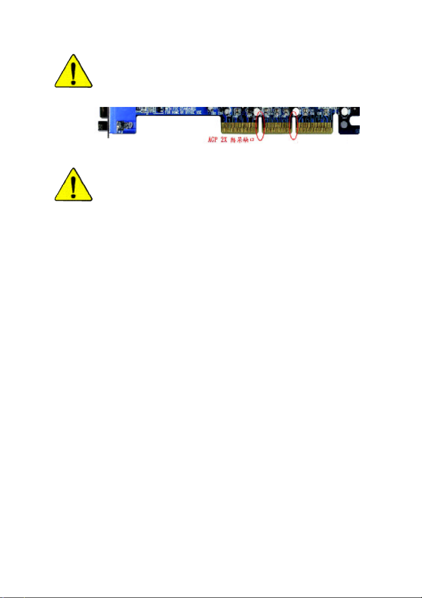
當您安裝AGP 卡時,請注意下述注意事項。
您的顯示卡若有AGP 4X/8X 防呆缺口(如下圖),請再次確
認此卡的規格為AGP 4X/ 8X(1.5V)。
AGP 4X/8X 防呆缺口
不要使用AGP 2X 卡,因為VIA® KM400A晶片組不支援
AGP 2X(3.3V),若您使用 AGP 2X (3.3V)卡時,可能造成系統
無法正常開機的情況,所以請使用AGP 4X/8X(1.5V)卡。
範例一:Diamond Vipper V770 這塊顯示卡的金手指部份設計成
2X/4X插槽皆可使用,透過Jumper 可切換於 2X 或 4X ,出廠預
設值為2X(3.3V),若您使用此卡在 GA-7VM 400AM(F)主機板
上,而且沒有將Jumper 切換至4X (1.5V)的模式時,可能造成
系統無法正常開機的情況。
範例二:某些SiS 305及Power Color所生產的某些ATi Rage 128
Pro 等顯示卡的金手指部份設計成 2X/4X插槽皆可使用,但只
支援2X(3.3V),若您使用此卡在GA-7VM400AM(F)主機板上,
可能造成系統無法正常開機的情況。
注意:技嘉科技所生產的AG32S(G)顯示卡,雖然採用ATi
Rage 128 Pro 晶片,但此卡設計符合 AGP4X(1.5V)的規格,因
此不會發生如範例二中可能造成系統無法正常開機的情況,
請您安心使用。
本手冊所有提及之商標與名稱皆屬該公司所有。
在科技迅速的發展下,此發行手冊中的一些規格可能會
有過時不適用的敘述,敬請見諒。
在此不擔保本手冊無任何疏忽或錯誤亦不排除會再更新
發行。手冊若有任何內容修改,恕不另行通知。
主機板上的任何貼紙請勿自行撕毀,否則會影響
到產品保固期限的認定標準。

Declaration of Conformity
G.B.T. Technology Träding GMbH
Ausschlager Weg 41, 1F, 20537 Hamburg, Germany
( description of the apparatus, system, installation to which it refers)
(reference to the specification under which conformity is declared)
in accordance with 89/336 EEC-EMC Directive
o EN 55011 Limits and methods of measurement
o EN 55013
o EN 55014 Limits and methods of measurement
o EN 55015 Limits and methods of measurement
o EN 55020
T EN 55022 Limits and methods of measurement
o DIN VDE 0855
o p art 10
o p art 12
T CE ma rking
o EN 60065
o EN 60335
of radio disturbance characteristics of
industrial,scientific and medic al (ISM
high frequency equipment
Limits and methods of measurement
of radio disturbance characteristics of
broadcast receivers and associated
equipment
of radio disturbance characteristics of
household electrical appliances,
portable tools and similar electrical
apparatus
of radio disturbance characteristics of
fluorescent lamps and luminaries
Immunity from radio interference of
broadcast receivers and associated
equipment
of radio disturbance characteristics of
information technology equipment
Cabled distribution systems; Equipment
for rece iving and/or distribution from
sound and television signals
The manufacturer also declares the conformity of above mentioned product
with the actual r equired safety standards in accordance with LVD 73/23 EEC
Safety requirements for mains operated
electronic and related apparatus for
household and similar general use
Safety of household and similar
electrical appliances
(S tamp)
We, Manufacturer/Importer
(full address)
declare that the product
Mother Board
GA-7VM400AM(F)
is in conformity with
o EN 61000- 3-2*
T EN 60555-2
o EN 61000- 3-3* Disturbances in supply systems cause
T EN 60555-3
T EN 50081-1
T EN 50082-1
o EN 55081-2
o EN 55082-2
o ENV 55104
o EN5009 1-2
o EN 60950
o EN 50091-1
Manufa cturer/Importer
Date : December 22, 2003
Disturbances in supply systems cause
by household appliances and similar
electrical equipment “Harmonics”
by household appliances and similar
electrical equipment “Voltage fluctuations”
Generic emission standard Part 1:
Residual commercial and light industry
Generic immunity standard Part 1:
Residual commercial and light industry
Generic emission standard Part 2:
Industrial environment
Generic emission standard Part 2:
Industrial environment
lmmunity requirements for household
appliances tools and similar apparatus
EMC requirements for uninte rruptible
powe r systems (UPS)
(EC confor mity marking)
Safety for information technology equipment
including electrical bussiness equipment
General and Safety requir ments for
uninterruptible power systems (UPS)
Signature:
Name:
Timmy Huang
Timmy Huang
DECLA RATION OF CONFORMITY
Per FCC Part 2 Section 2.1077(a)
Resp onsible PartName:
Add ress:
Ph one/Fax No:
hereby declares that the product
Produ ct Name:
Model Number:
Conforms to the following specifications:
FCC Part 15, Subpart B, Section 15.107(a) and Section 15.109(a),
Class B Digital Device
Su pplementary Information:
This device complies with part 15 of the FCC Rules. Operation is
subject to the following two conditions: (1) This device may not
cause harmful and (2) this device must accept any inference received,
including that may cause undesired operation.
Representative Person’s Name:
Signature:
G.B.T. INC . (U.S.A.)
17358 Railroad Street
City of Industry, CA 91748
(818) 854-9338/ (818) 854-9339
Moth erboard
GA-7VM400AM(F)
ERIC LU
Eric Lu
Date:
December 22 ,2003

7VM400AM(F)
AMD Socket A
AMD AthlonTM / AthlonTM XP/ Duron
Rev. 1003
12MC-7VM400AM-1003
TM
Socket A
............................................................................ 4
....................................................................... 5
.............................................................................................................. 5
GA-7VM400AM(F) Layout .................................................................... 7
............................................................................... 8
.................................................. 10
1 Switch (SW1) ...................................................................... 11
2 (CPU) ................................................................... 12
2-1 ................................................................................. 12
2-2 ................................................................ 13
3 ............................................................................. 14
4 ...................................................................................... 16
5: ............ 17
5-1 I/O ........................................................................... 17
5-2 ................................................................................................... 19
BIOS .................................................. 31
(BIOS E4) .................................................. 32
CMOS ................................................................................... 34
BIOS ............................................................................ 37
....................................................................................... 39
....................................................................................... 43
- 2 -GA-7VM400AM(F)
PCI ................................................................ 45
....................................................................................... 46
/ .................................................................................... 47
Fail-Safe ........................................................................... 49
Optimized ......................................................................... 50
(Supervisor)/ (User) ................................... 51
SETUP .......................................................... 52
SETUP ..................................................... 53
......................................... 57
Easy TuneTM 4 ................................................................................. 57
@ BIOS
BIOS
Jack-Sensing
Xpress Recovery
Serial ATA RAID BIOS
TM
........................................................................................ 58
............................................................................. 59
/ / ................................................ 74
......................................................................... 80
............................................................................. 82
......................................... 85
..................................................................... 93
- 3 -
1.
2.
3. (CPU RAM)
4.
5. ATX
PCB
- 4 -GA-7VM400AM(F)
z Micro ATX 24.4 x 23.3
z AMD AthlonTM / AthlonTM XP / DuronTM (K7) Socket A
128K 512K/256K/64K
CPU 200/266/333/400 MHz FSB
z
z VIA KM400A Memory/AGP/PCI
z VT8237
z 2 184-pin DDR DIMM
z DDR400DDR333/DDR266/DDR200 DIMM
z 2GB DDR
z
I/O z IT8705
z 1 AGP , 8X/4X/2X (1.5V)
z 3 PCI
IDE z 2 IDE bus master (UDMA 33/ATA 66/ATA 100/ATA133) IDE
z PIO mode 3 4(UDMA33/ATA66/ATA100/ATA133) IDE
SATA z 2 Serial ATA
z CPU /
z CPU /
z CPU /
z
z 1 (360K, 720K, 1.2M, 1.44M
z 1
z 1 (COMA) 1 VGA COMB
z
z 3
z 1
1.4 GHz
2.5V DDR DIMM
33MHz PCI2.2 compliant
4 ATAPI
ATAPI CD-ROM
( 1)
2.88M bytes)
8 USB 2.0/1.1
(
x 4 x 4)
IEEE1394 ( ) (*
Normal/EPP/ECP
)
( 1) SATA 1.5 Gb/s
(*)
GA-7VM400AMF
.......
- 5 -
SATA RAID z VT8237
z
z
Disk striping (RAID0) DISK Mirroring (RAID1)
UDMA up to 150 MB/sec
z 2 SATA
z CODEC (RealTek ALC655)
z Jack-Sensing
z Line Out : 2
z Line In : 2 ( )
z Mic In : / ( )
z SPDIF Out/SPDIF In
z CD_In / Game Connector
USB2.0 z VIA VT8237
z RTL8100C (10/100 Mbit)
z 1 RJ45
IEEE1394 (*
)
z Ti TSB43AB23
PS/2 z PS/2 PS/2
BIOS z Award BIOS
z Q-Flash
z PS/2 PS/2
z
z STR (Suspend-To-RAM)
z AC Recovery
z
z USB / S3
z Thermal shutdown
z @BIOS
TM
z Easy Tune 4
z (DDR/CPU)
z (DDR/AGP)
(*)
CPU CPU
CPU
GA-7VM400AMF
- 6 -GA-7VM400AM(F)
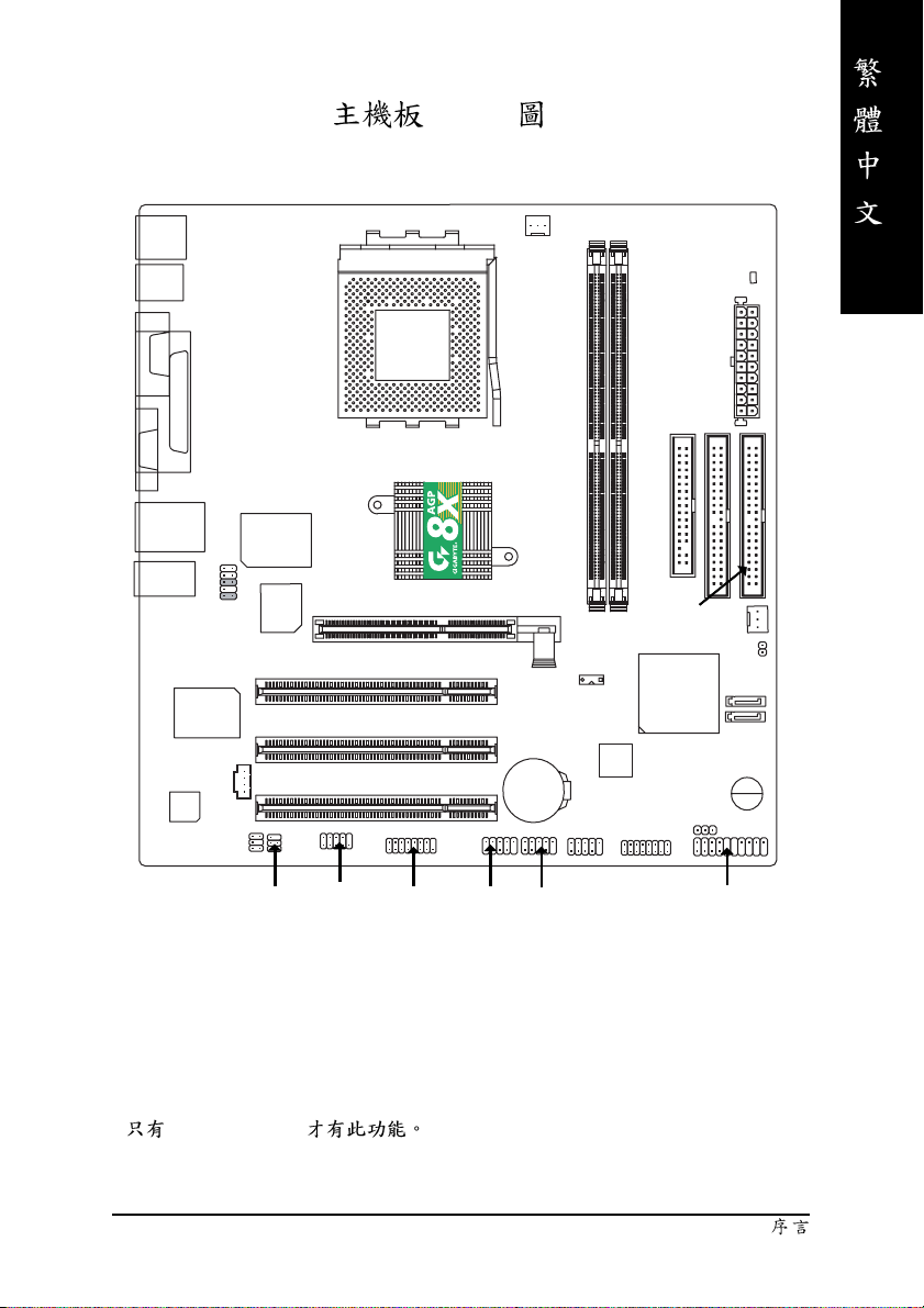
GA-7VM400AM(F) Layout
KB_MS
USB
COMA
VGA
USB
MIC_IN
LPT
LINE_OUT
RTL8100C
CODEC
LAN
LINE_IN
F_AUDIO
SUR_CEN
IT8705
BIOS
CD_IN
AGP 8X
SOCKET A
VIA KM400A
PCI3
PCI1
PCI2
CPU_FAN
GA-7VM400AM(F)
AGP
SW1
TSB43AB23 (*
BAT
F1_1394 (*
DDR1
DDR2
)
F2_1394 (*
FDD
IDE2
VT8237
)
RAM_LED
ATX
IDE1
SYS_FAN
CLR_CMOS
PWR_LED
)
SATA1
SATA0
BZ
(*)
SPDIF_IO
GA-7VM400AMF
COMB
GAME
- 7 -
F_USB1
F_USB2
F_PANEL
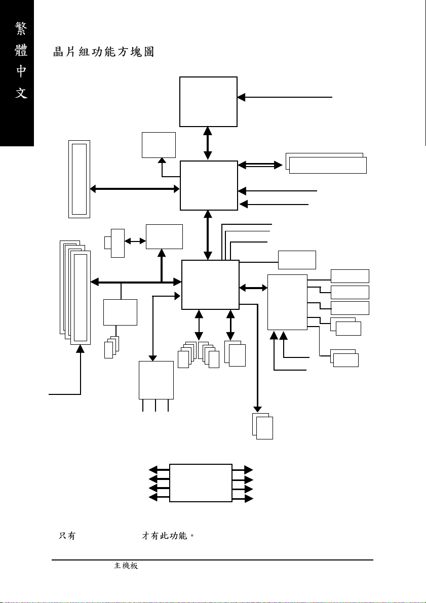
AMD-K7
Host CUP
TM
CPUCLK+/- (100/133/166/200MHz)
AGP 2X/4X/8X
3 PCI
PCICLK
(33MHz)
AGPCLK
RJ45
PCI BUS 33MHz
TSB43AB23 (*
IEEE1394 (*
66MHz
)
VGA Port
RTL8100C
)
AC97 Link
6 Channel
CODEC
MIC
LINE-IN
KM400A
8 USB
Ports
LINE-OUT
System Bus
200/266/333/400MHz FSB
VIA
66MHz V_Link
VIA
VT8237
ATA33/66/
100/133
IDE Channels
200/266/333/400MHz
DDR
HCLK+/- (100/133/166/200MHz)
AGPCLK66 MHz
33 MHz
48 MHz
14.318 MHz
BIOS
LPC BUS
IT8705
24 MHz
33 MHz
Serial ATA
Channels
Game Port
Floppy
LPT Port
PS/2 KB/Mouse
2 COM Ports
(*)
PCICLK (33MHz)
USBCLK (48MHz)
14.318 MHz
33 MHz
GA-7VM400AMF
CLK
GEN
HCLK+/- (100/133/166/200MHz)
CPUCLK+/- (100/133/166/200MHz)
AGPCLK (66MHz)
V_Link (66MHz)
- 8 -GA-7VM400AM(F)
- 9 -
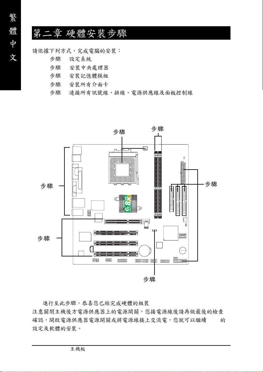
1 - Switch (SW1)
2 - (CPU)
3 -
4 -
5 -
4
5
2
3
5
1
!!
BIOS
- 10 -GA-7VM400AM(F)
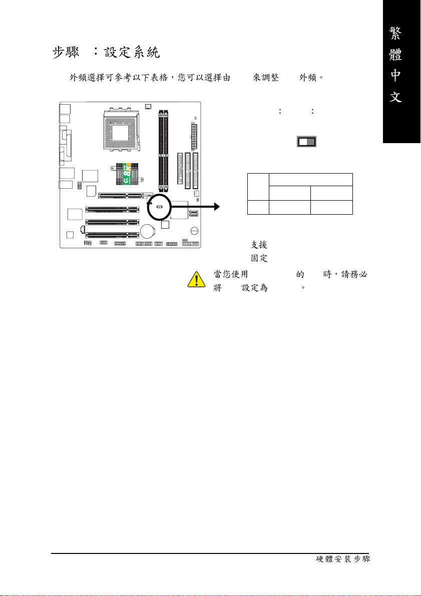
1 Switch (SW1)
CPU SW1 CPU
O ON / X OFF
ON
SW1 CPU CLOCK
100 AUTO
1 O N OFF
Auto : FSB 266/333/400 MHz CPU
100MHz :
SW1 100MHz
FSB 200MHz CPU
FSB 200MHz CPU
SW1
1
- 11 -
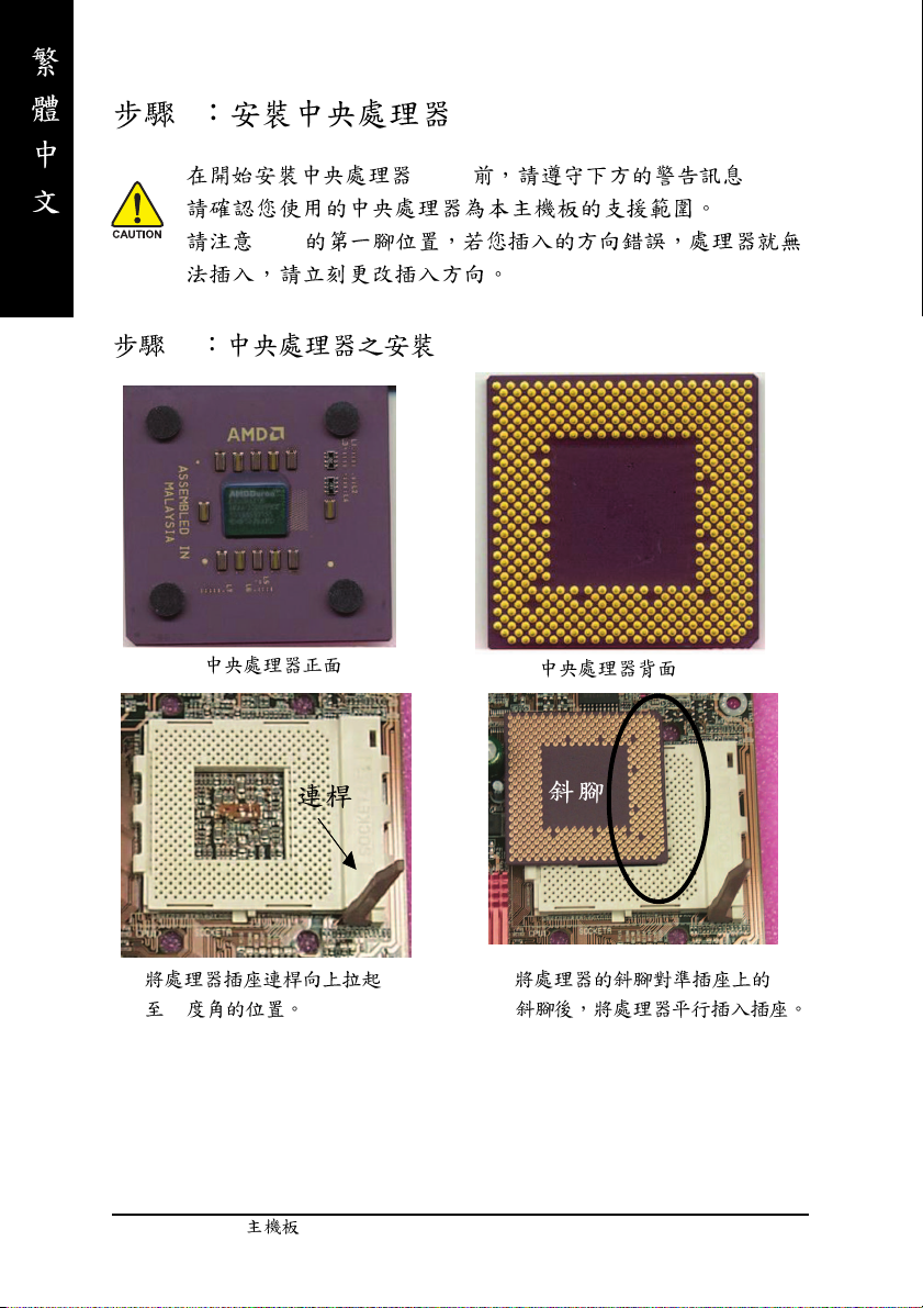
2 (CPU)
(CPU) :
CPU
2-1
1.
90
2.
- 12 -GA-7VM400AM(F)
2-2
1. AMD
2. CPU
3.
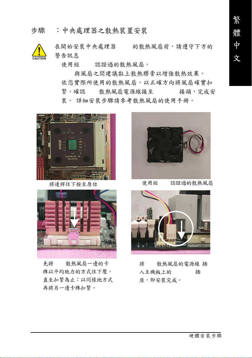
(CPU)
:
CPU CPU FAN
( )
1.
3. CPU
2. AMD
4. CPU
CPU_FAN
- 13 -
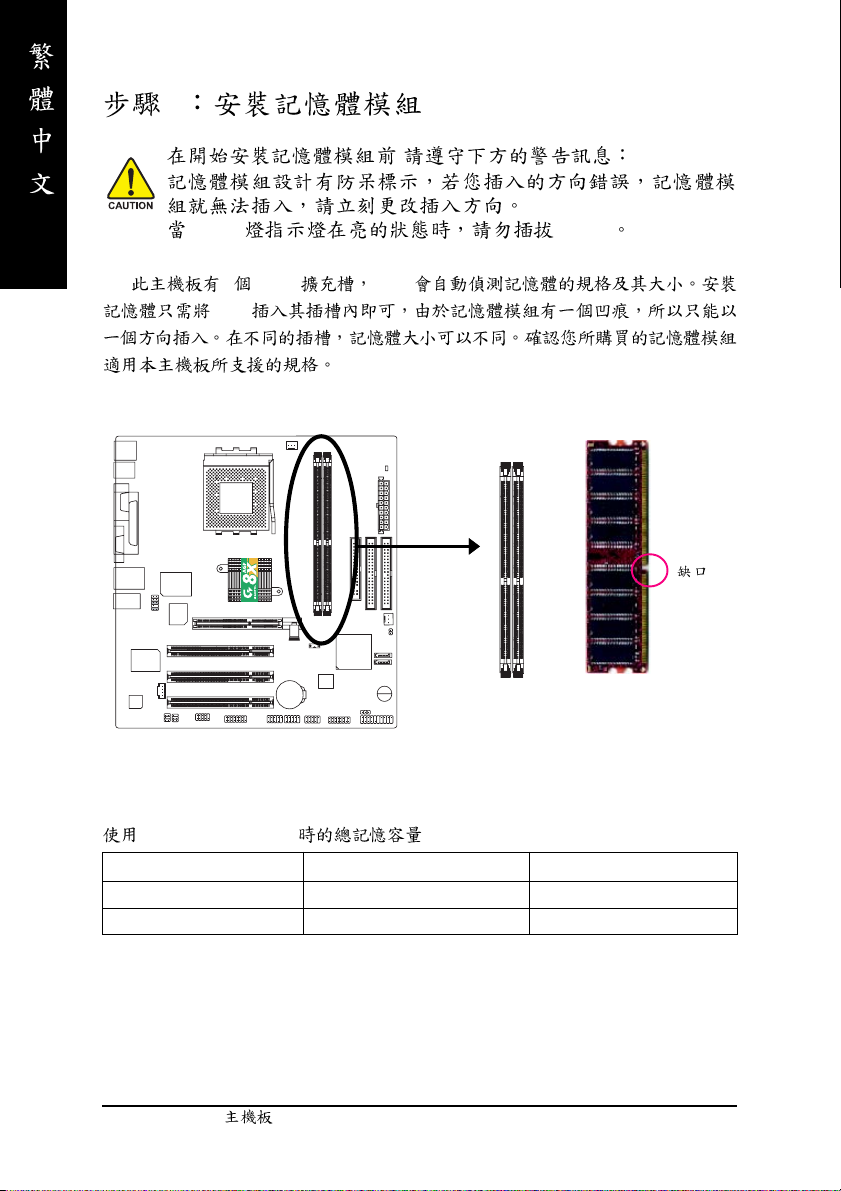
3
,
DIMM DIMM
2 (DIMM) BIOS
DIMM
DDR
Unbuffered DDR DIMM
64 Mbit (2Mx8x4 banks) 64 Mbit (1Mx16x4 banks) 128 Mbit(4Mx8x4 banks)
128 Mbit(2Mx16x4 banks) 256 Mbit(8Mx8x4 banks) 256 Mbit(4Mx16x4 banks)
512 Mbit(16Mx8x4 banks) 512 Mbit(8Mx16x4 banks)
- 14 -GA-7VM400AM(F)
1.
2.
3.
DIMM
DDR
DDR(Double Data Rate) PC SDRAM
SDRAM DDR
OEM
DDR SDRAM
SDRAM DDR SDRAM
DDR 3.2GB/s(DDR400)
DDR DRAM
PC
- 15 -
4
1.
2. (
)
3.
4.
5.
6.
7. BIOS
8.
AGP
AGP
AGP
/ AGP
AGP
- 16 -GA-7VM400AM(F)
5:
5-1 I/O
X
Y
X PS/2 PS/2
PS/2
(6 pin Female)
PS/2
(6 pin Female)
Y/[ ,
USB 7 (
USB 6 ( 6)
LAN ( )
Z[
\
PS/2
PS/2
10/100Mbps
7)
USB USB USB
USB ZIP USB .
USB 5 ( 5)
USB 4 ( 4)
USB
- 17 -
Z COMA( A)/VGA( )/LPT( )
(25 pin Female)
A
(15 pin Female)
(9 pin Male)
\
Line In (Rear Speaker)
Line Out (Front Speaker)
MIC In (Center and Subwoofer)
2-/4-/6- 74
2-/4-/6-
6-channel
2
:
"Line Out"
"Line In"
"Mic In"
:
P.25
SUR_CEN
- 18 -GA-7VM400AM(F)
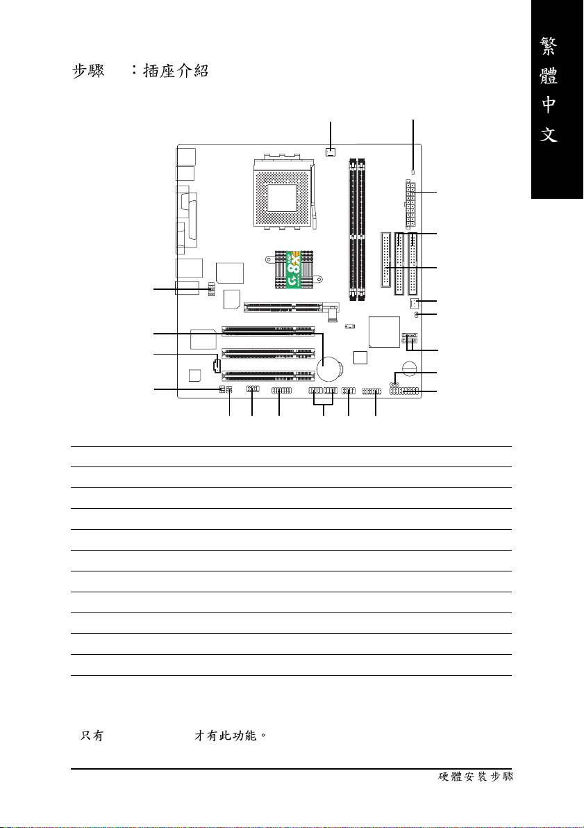
5-2
1
10
9
12
11
13
16
15
)
17(*
14
1) CPU_FAN 12) CD_IN
2) SYS_FAN 13) SPDIF_IO
3) ATX 14) F_USB1/F_USB2
4) IDE1/IDE2 15) COMB
5) FDD 16) GAME
6) RAM_LED 17) F1_1394 (*
7) F_PANEL 18) F2_1394 (*
)
)
8) PWR_LED 19) SATA0/SATA1
9) BAT 20) CLR_CMOS
10) F_AUDIO
11) SUR_CEN
18(*
6
3
4
5
2
20
19
8
7
)
(*)
GA-7VM400AMF
- 19 -
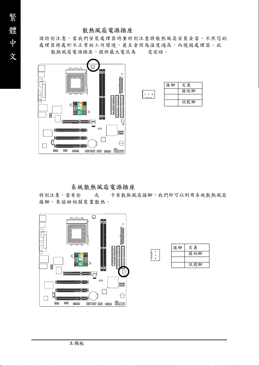
1) CPU_FAN (CPU )
CPU 600
2) SYS_FAN ( )
AGP PCI
1
1
2 +12V
3
1
1
2 +12V
3
- 20 -GA-7VM400AM(F)
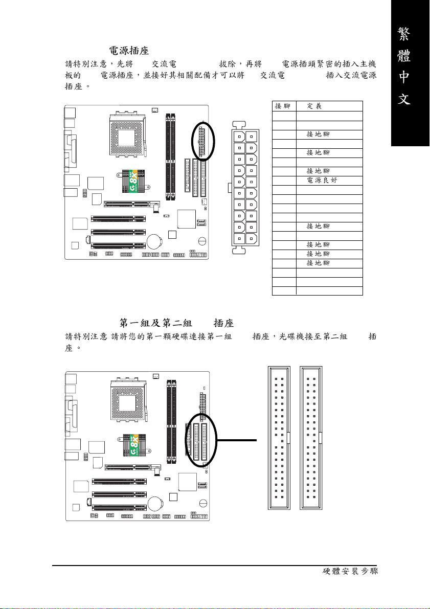
3) ATX (ATX )
AC (110/220V) ATX
ATX AC (110/220V)
11
20
4) IDE1/ IDE2( IDE )
: IDE IDE
1 3.3V
2 3.3V
3
1
4 VCC
5
6 VCC
7
8
9 5V SB(stand by +5V)
10 +12V
11 3.3V
12 -12V
13
14 PS_ON(softOn/Off)
10
15
16
17
18 -5V
19 VCC
20 VCC
- 21 -
40
2
IDE1
39
1
IDE2
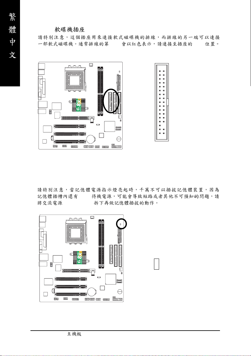
5) FDD ( )
1Pin Pin1
6) RAM_LED
2.5V
(AC110/220V)
34
2
33
1
+
-
- 22 -GA-7VM400AM(F)
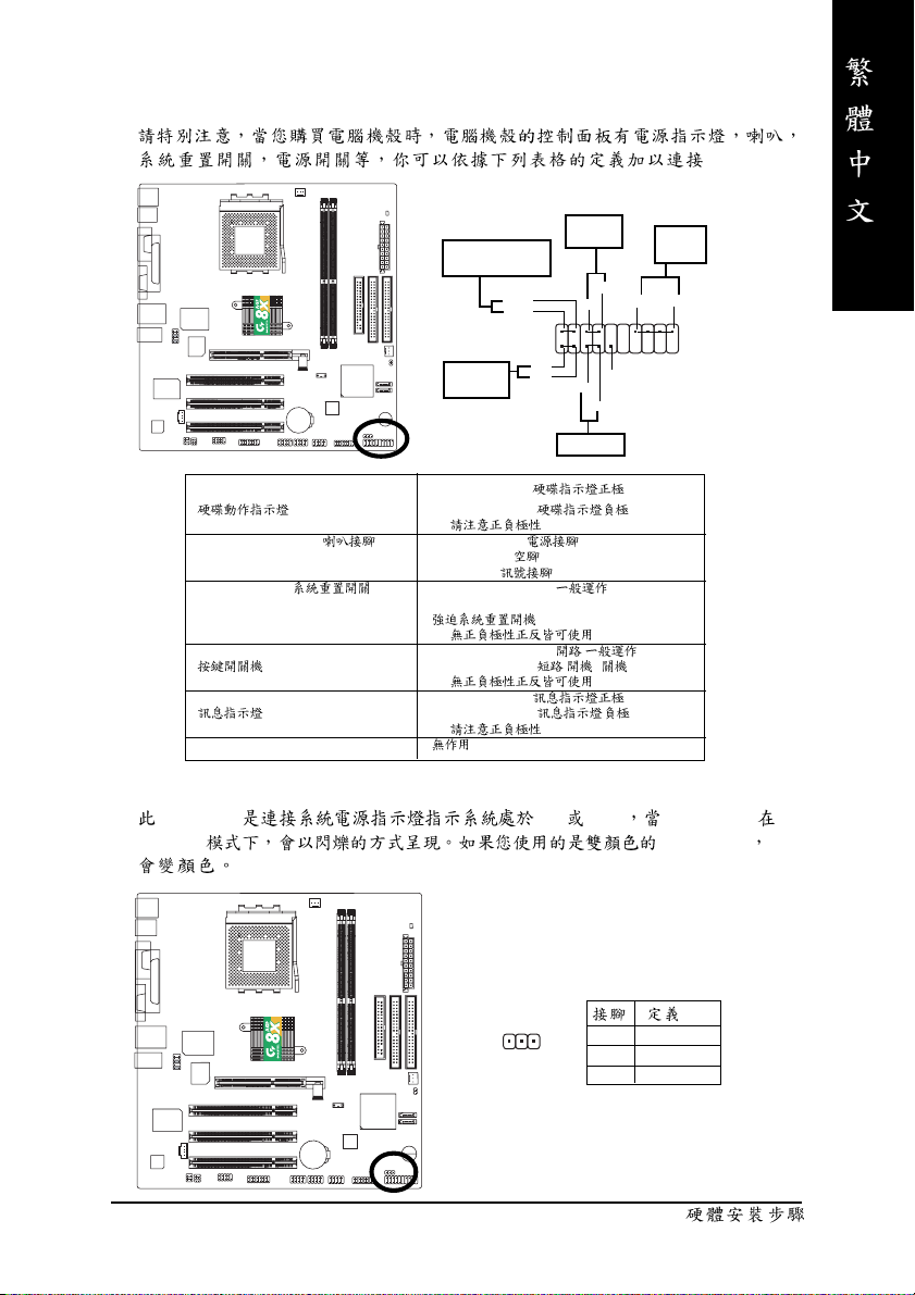
7) F_PANEL (2x10 pins connector)
.
Message LED/Power/
Sleep LED
MSG-
MSG+
IDE Hard Disk
Active LED
HD+
HD-
Soft Power
Connector
2
1
1
1
Reset Switch
PW+
1
RES-
RES+
PW-
Speaker
Connector
SPK-
SPK+
20
1
1
NC
19
HD (IDE Hard Disk Active LED) Pin 1: LED anode(+)
Pin 2: LED cathode(-)
SPK (Speaker Connector) Pin 1: VCC(+) +5v
RES (Reset Switch) Open: Normal Operation
PW (Soft Power Connector) Open: Normal Operation :
MSG(Message LED/Power/Sleep LED) Pin 1: LED anode(+)
NC
0
Pin 2- Pin 3: NC
Pin 4: Data(-)
Close: Reset Hardware System
0
Close: Power On/Off : /
0
Pin 2: LED cathode(-)
0
8) PWR_LED
PWR_LED ON OFF Power LED
Suspend power LED LED
- 23 -
1
1 MPD+
2 MPD3 MPD-
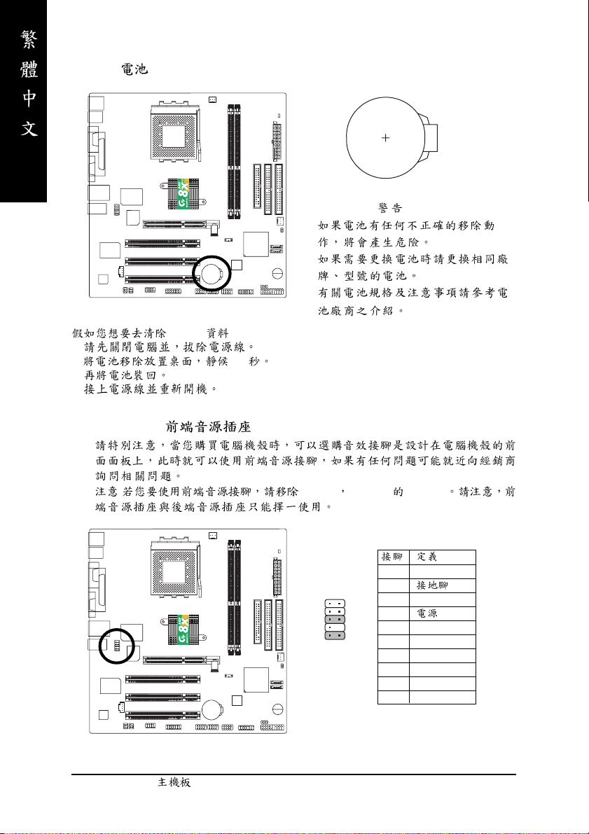
9) BAT( )
+
1.
CMOS ...
2. 30
3.
4.
10) F_AUDIO ( )
: Pin5-6 Pin9-10 Jumper
12
109
1 MIC
2
3 REF
4
5 FrontAudio(R)
6 RearAudio(R)
7 Reserved
8 No Pin
9 FrontAudio (L)
10 RearAudio(L)
- 24 -GA-7VM400AM(F)
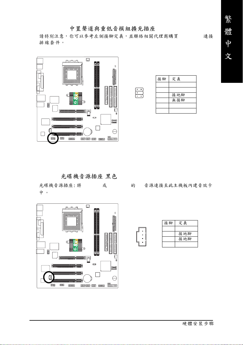
11) SUR_CEN( )
2
1
5
6
12) CD_IN ( , )
CD-ROM DVD-ROM CD
SUR_CEN
1 SUR OUTL
2 SUR OUTR
3
4
5 CENTER_OUT
6 BASS_OUT
- 25 -
1
1 CD-L
2
3
4 CD_R
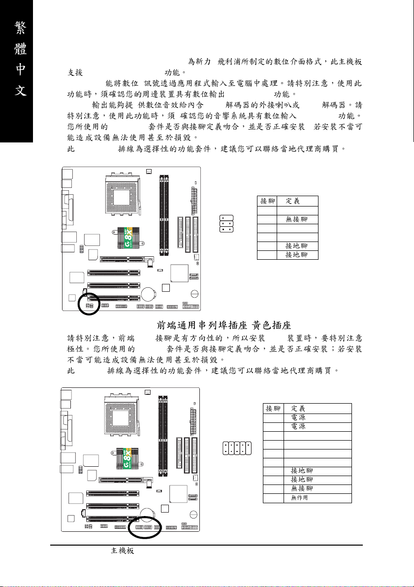
13) SPDIF_IO (SPDIF In/Out)
Sony/Philip Digital Interface Format /
SPDIF IN & SPDIF OUT
SPDIF IN
(SPDIF Out)
SPDIF AC-3 AC-3
(SPDIF In)
SPDIF_IO ;
SPDIF_IO
2
1
6
5
1 VCC
2
3 SPDIF
4 SPDIFI
5
6
14) F_ USB1 / F_USB2( , )
USB USB
F_USB
F_USB
1
2
2
1
3 USB0 DX-/USB2 DX-
10
4 USB1 Dy-/USB3 Dy5 USB0 DX+/USB2 DX+
9
6 USB1 Dy+/USB3 Dy+
7
8
9
10
- 26 -GA-7VM400AM(F)
 Loading...