

Gigabyte GA-7VKMLE User Manual

M The author assumes no responsibility for any
errors or omissions that may appear in this
document nor does the author make a
commitment to update the information
contained herein.
M Third-party brands and names are the
property of their respective owners.
M Please do not remove any labels on
motherboard, this may void the warranty of
this motherboard.
M Due to rapid change in technology, some of
the specifications might be out of date
before publicution of this booklet.

Declaration of Conformity
G.B.T. Technology Träding GMbH
Auss chlage r Weg 41 , 1F, 20 537 Hamburg, Ge rmany
( description of the apparatus, system, inst allation to which it refers)
(refere nce to the specification under wh ich conformity is declare d)
in accordance with 89/336 EEC-EMC Directive
o EN 55011 Limits and met hods of measurement
o EN 55013
o EN 55014 Limits and met hods of measurement
o EN 55015 Limits and met hods of measurement
o EN 55020
T EN 55022 Limits and methods of measurement
o DIN VDE 0855
o p art 10
o p art 12
T CE marking
o EN 60065
o EN 60335
of radio disturbance characteristics of
industrial,scientific and medical (ISM
high frequency equipment
Limits and met hods of measurement
of radio disturbance characteristics of
broadcast receivers and associated
equipment
of radio disturbance characteristics of
household electrical appliances,
portable tools and similar electrical
apparatus
of radio disturbance characteristics of
fluorescent lamps and luminaries
Immunity from radio interference of
broadcast receivers and associated
equipment
of radio disturbance characteristics of
information technology equipment
Cabled distribution systems; Equipment
for receiving and/or distribution from
sound and television signals
The manufacturer also decl ares the conformity of above mentioned product
with the actual required safety standards in accordance with LVD 73/23 EEC
Safety requirements for mains operated
electronic and related apparatus for
household and similar general use
Safety of household and similar
electrical appliances
(Stamp)
We, Manufac turer/Importer
(full address)
declare that t he produc t
Mother Board
GA-7VKMLE
is in conformity with
o EN 61000- 3-2*
T EN 60555-2
o EN 61000- 3-3* Disturban ces in supply systems cause
T EN 60555-3
T EN 50081-1
T EN 50082-1
o EN 55081-2
o EN 55082-2
o E NV 55104
o EN5009 1-2
o EN 60950
o EN 50091-1
Manufa cturer/Importer
Date : Septem ber 30, 2002
Disturbances in supply syst ems cause
by household appliances and similar
electrical equipment “Harmonics”
by household appliances and similar
electrical equipment “Voltage fluctuations”
Generic emission standard Part 1:
Residual commercial and light industry
Generic immunity standard Part 1:
Residual commercial and light industry
Generic emission standard Part 2:
Industrial environment
Generic emission standard Part 2:
Industrial environment
lmmunity requirements for household
appliances tools and similar apparatus
EMC requirements for uninte rruptible
power systems (UPS)
(EC confor mity marking)
Safety for information technology equipment
including electrical bussiness equipment
General and Safety require ments for
uninterruptible pow er systems (UPS)
Signature:
Name:
Timmy Huang
Timmy Huang
DECLARATION OF CONFORMITY
Per FCC Part 2 Section 2.1077(a)
Responsible Party Name:
Add ress:
Phone/Fax No:
hereby declares that the product
Produ ct Name:
Model Nu mber:
Conforms to the following specifications:
FCC Part 15, Subpart B, Section 15.107(a) and Section 15.109(a),
Class B Digital Device
Supplementary Information:
This device complies with part 15 of the FCC Rules. Operation is
subject to the following two conditions: (1) This device may not
cause harmful and (2) this device must accept any inference received,
including that may cause undesired operation.
Representative Person’s Name:
Signature:
G.B.T. INC. (U.S.A.)
17358 Railroad Street
City of Indu stry, CA 91748
(818) 854-9338/ (818) 854-9339
Motherboard
GA-7VKMLE
ERIC LU
Eric Lu
Date:
September 30,2002

GA-7VKMLE
AMD Socket A Processor Motherboard
USER’S MANUAL
AMD Socket A Processor Motherboard
Rev. 4001
12ME-7V KMLE-4001

Table of Content
English
Item Checklist .....................................................................................4
WARNING! .......................................................................................... 4
Chapter 1 Introduction .........................................................................5
Chapter 2 Hardware Installation Process ..............................................8
Features Summary ......................................................................................... 5
GA-7VKMLE Motherboard Layout ................................................................. 7
Step 1: Install the Central Processing Unit (CPU) ........................................ 9
Step1-1: CPU Speed Setup .....................................................................................................9
Step1-2: CPU Installation ....................................................................................................... 10
Step1-3: CPU Cooling Fan Installation .................................................................................. 11
Step 2: Install memory modules .................................................................. 12
Step 3: Install expansion cards .................................................................... 14
Step 4: Connect ribbon cables, cabinet wires, and power supply ............ 15
Step 4-1: I/O Back Panel Introduction ....................................................................................15
Step 4-2: Connectors Introduction ...........................................................................................17
Chapter 3 BIOS Setup ....................................................................... 25
The M ain Menu (For example: BIOS Ver. : F2a) ....................................... 26
Standard CMOS Features ........................................................................... 28
BIOS Features Setup .................................................................................... 31
Chipset Features Setup ................................................................................ 33
Power Management Setup .......................................................................... 36
- 2 -GA-7VKMLE Motherboard

PNP/PCI Configuration ................................................................................. 3 9
Load Fail-Safe Defaults ................................................................................ 41
Load Optimized Defaults .............................................................................. 42
Integrated Peripherals .................................................................................. 43
Hardware Monitor & MISC Setup ................................................................ 4 7
Set Supervisor / User Password ................................................................... 48
IDE HDD Auto Detection ............................................................................... 49
Save & Exit Setup .......................................................................................... 5 0
Exit Without Saving ........................................................................................ 51
Chapter 4 Technical Reference .......................................................... 53
Block Diagram .............................................................................................. 5 3
@ BIOSTM Introduction .................................................................................. 54
Easy TuneTM 4 Introduction .......................................................................... 55
Flash BIOS Method Introduction ................................................................. 5 6
Chapter 5 Appendix .......................................................................... 61
EnglishEnglish
- 3 -
Table of Content
Item Checklist
þ The GA-7VKMLE motherboard o 2 Port USB Cable x 1
English
þ IDE cable x 1/ Floppy cable x 1 o 4 Port USB Cable x 1
þ CD for motherboard driver & utility o SPDIF KIT x 1(SPD-KIT)
þ GA-7VKMLE user's manual o IEEE 1394 Cable x1
þ I/O Shield o Audio Combo Kit x 1
o Quick PC Installation Guide o Motherboard Settings Label
o RAID Manual
Computer motherboards and expansion cards contain very delicate Integrated Circuit (IC) chips. To
protect them against damage from static electricity, you should follow some precautions whenever
you work on your computer.
Installing the motherboard to the chassis…
there are no slots to attach the spacers, do not become alarmed you can still attach the spacers to
the mounting holes. Just cut the bottom portion of the spacers (the spacer may be a little hard to
cut off, so be careful of your hands). In thi s way you can still attach th e motherboard to the base
without worrying about short circuits. Sometimes you may need to use the plastic springs to isolate
the screw from the motherboard PCB surface, because the circuit wire may be near by the hole. Be
careful, don’t let the screw contact any printed c ircuit write or parts on the PCB that are near the
fixing hole, otherwise it may damage the board or cause board malfunctioning.
WARNING!
1. Unplug your computer when working on the inside.
2. Use a grounded wrist strap before handling computer components. If you do not have
one, touch both of your hands to a safely grounded object or to a metal object, such as
the power supply case.
3. Hold components by the edges and try not touch the IC chips, leads or connectors, or
other components.
4. Place components on a grounded antistatic pad or on the bag that came with the
components whenever the components are separated from the system.
5. Ensure that the ATX power supply is switche d off before you plug in or remove the ATX
power connector on the motherboard.
If the motherboard has mounting holes, but they don’t line up with the holes on the base and
- 4 -GA-7VKMLE Motherboard

Chapter 1 Introduction
Features Summary
Form Factor — 24.3cm x 19cm Micro ATX size form factor, 4 layers PCB.
CP U — Socket A processor
AMD AthlonTM/AthlonTM XP/Duron
128K L1 & 256K/64K L2 cache on die
— Supports 1.4GHz and faster
— 200/266MHz FSB and DDR bus speeds
Chipset — VIA KM266/KL266 Memory/AGP/PCI Controller (PAC)
— VIA VT8233 Low cost V-LINK Client Highly Intergated
Memory — 2 184-pin DDR DIMM sockets
— Supports PC1600 DDR or PC2100 DDR DIMM
— Supports up to 1GB DRAM (Max)
— Supports only 2.5V DDR DIMM
I/O Control — IT8700F
Slots — 3 PCI Slots Supports 33MHz & PCI 2.2 compliant
On-Board IDE — 2 IDE bus master (ATA66/100/133) IDE ports for up to 4
ATAPI devices
— Supports PIO mode3,4 (ATA66/100/133) IDE & ATAPI
CD-ROM
On-Board Peripherals — 1 Floppy port supports 2 FDD with 360K, 720K,1.2M, 1.44M
and 2.88M bytes.
— 1 Parallel port supports Normal/EPP/ECP mode
— 2 Serial port (COM A, Internal COM B)
— 1 VGA port
— 4 USB ports (Rear USB x 2, Front USB x 2)
Hardware Monitor — CPU temperature detect
TM
(K7) Socket A processor
English
to be conti nued......
Introduction- 5 -

On-Board Sound — AC97 CODEC
On-Board LAN — Build in RTL8100BL Chipset *
English
PS/2 Connector — PS/2 Keyboard interface and PS/2 Mouse interface
BIOS — Licensed AMI BIOS
Additional Features — STR(Suspend-To-RAM)
M Please set the CPU host frequency in accordance with your processor's specifications.
— Line In/Line Out/Mic In/CD_In/Game Port
— Build in RTL8101L Chipset **
— Support Q-Flash Utility
— AC Recovery
— USB KB/Mouse wake up from S3
— PS2 KB/Mouse wake up from S1, S3, S4, S5
— Supports @BIOS
— Supports Easy Tune
TM
TM
4
We don't recommend you to set the system bus frequency over the CPU's specification
because these specific bus frequencies are not the standard specifications for CPU,
chipset and most of the peripherals. Whether your system can run under these specific
bus frequencies properly will depend on your hardware configurations, including CPU,
Chipsets,SDRAM,Cards… .etc.
"*" for PCB Ver.: 3.1
"**" for PCB Ver.: 4.0
- 6 -GA-7VKMLE Motherboard
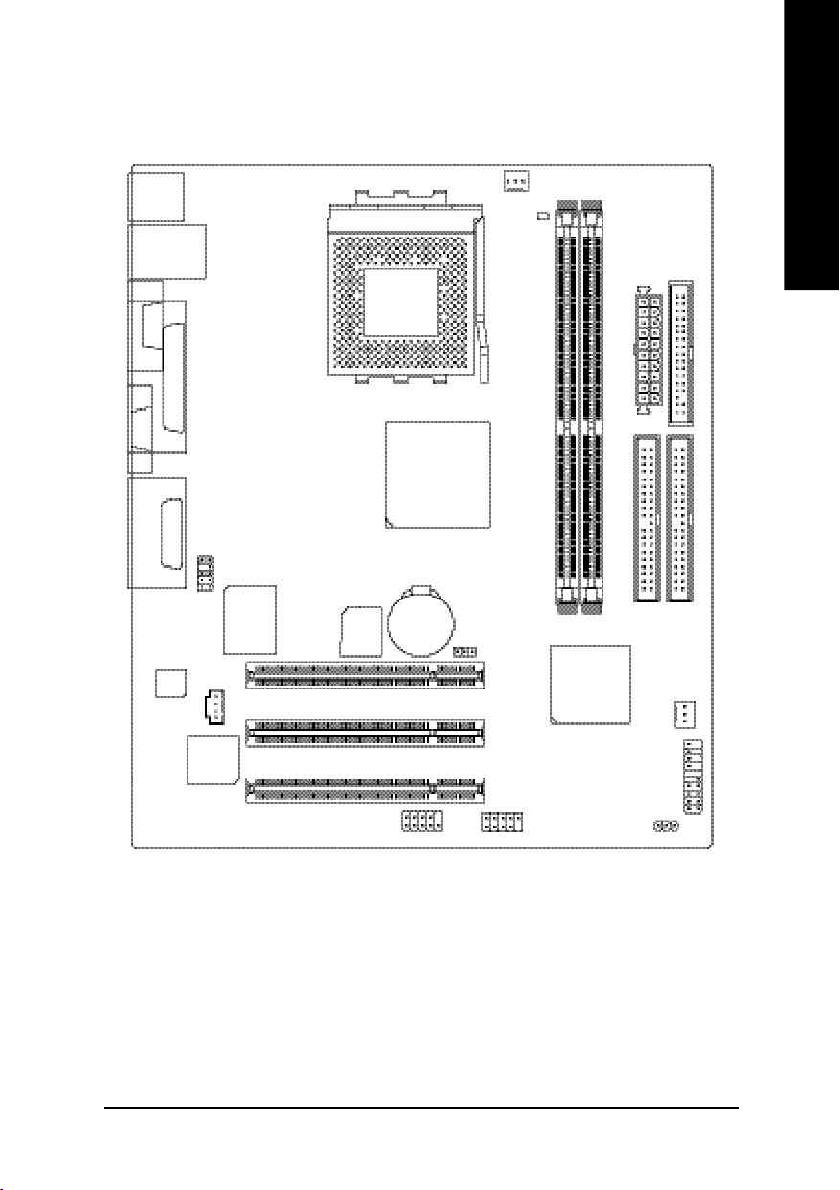
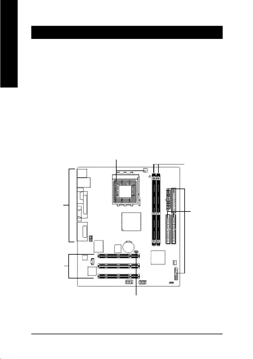
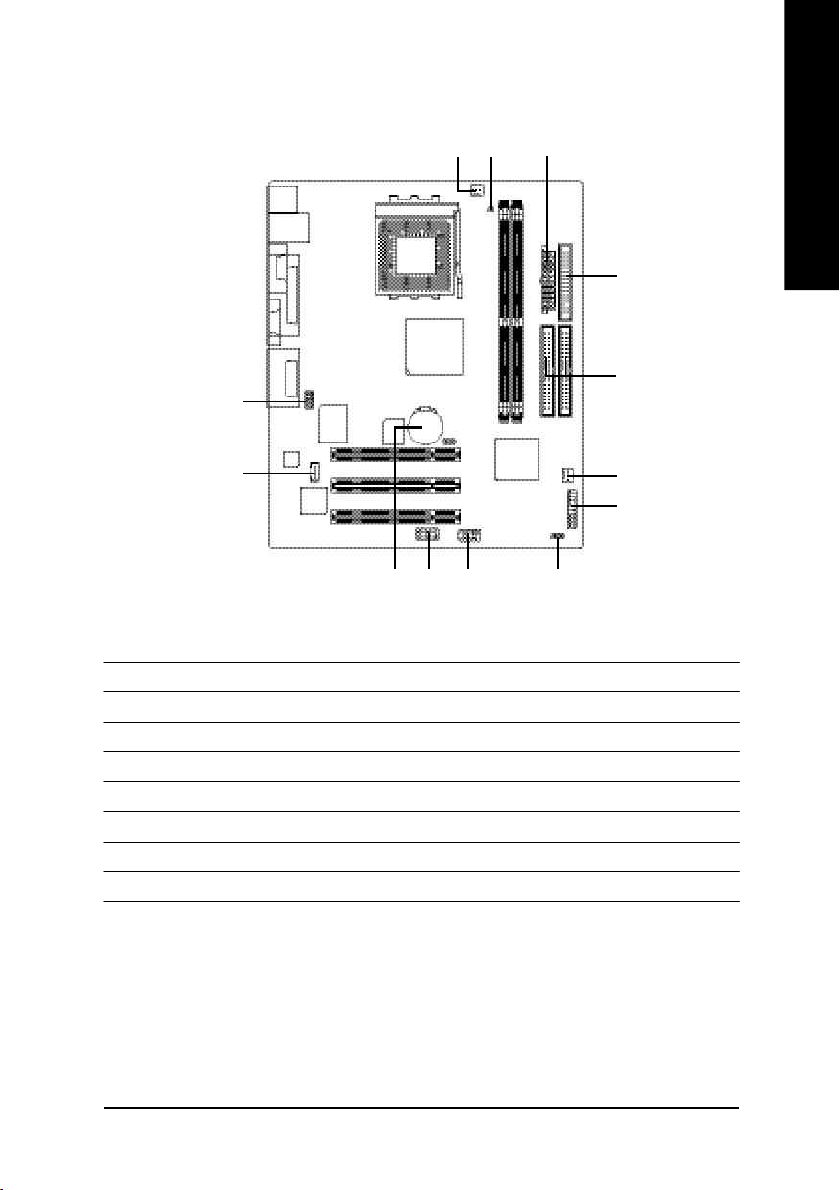
GA-7VKMLE Motherboard Layout
English
MS_KB
USB
COMA
VGA
LINE_OUT
LINE_IN
MIC_IN
CODEC
LAN
LPT
GAME
F_AU DIO
RTL8 10 0BL *
RTL 810 1L **
IT8 7 00 F
CD_IN
BIOS
SOCKET A
COMB
CPU _FAN
KM 266 /KL26 6
BAT
CLK _JP
PCI1
PCI2
PCI3
RAM _LED
GA-7VKMLE
DDR1
F_U SB1
VT8 2 33
FD D
ATX
IDE1
IDE2
DDR2
SYS_FAN
F_PANEL
PWR_ LED
"*" for PCB Ver.: 3.1
"**" for PCB Ver.: 4.0
Introduction- 7 -
Chapter 2 Hardware Installation Process
To set up your computer, you must complete the following setups:
English
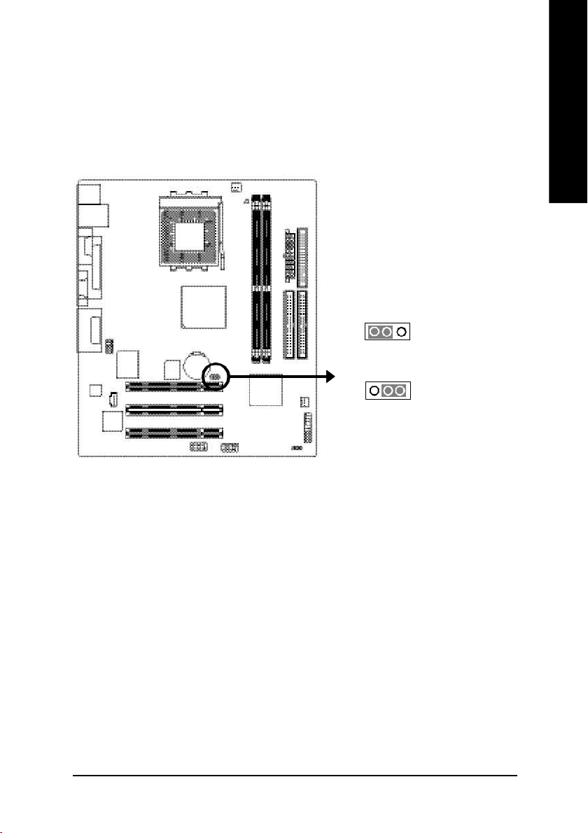
Step 1- Set system Jumper(CLK_JP)
Step 2- Install the Central Processing Unit (CPU)
Step 3- Install memory modules
Step 4- Install expansion cards
Step 5- Connect ribbon cables, cabinet wires, and power supply
Step 6- Setup BIOS software
Step 7- Install supporting software tools
Step 2
Step 3
Step 5
Step 5
Step 4
Step 1
- 8 -GA-7VKMLE Motherboard
Step 1: Install the Central Processing Unit (CPU)
Step1-1: CPU Speed Setup
The system bus frequency can be switched at 100/133MHz by adjusting CLK_JP.
(The frequency ratio depend on CPU.)
English
1
1
Default Setting: 10 0MHz
1-2 close: 100 MHz
2-3 close: 133 MHz
Hardware Installation Process- 9 -
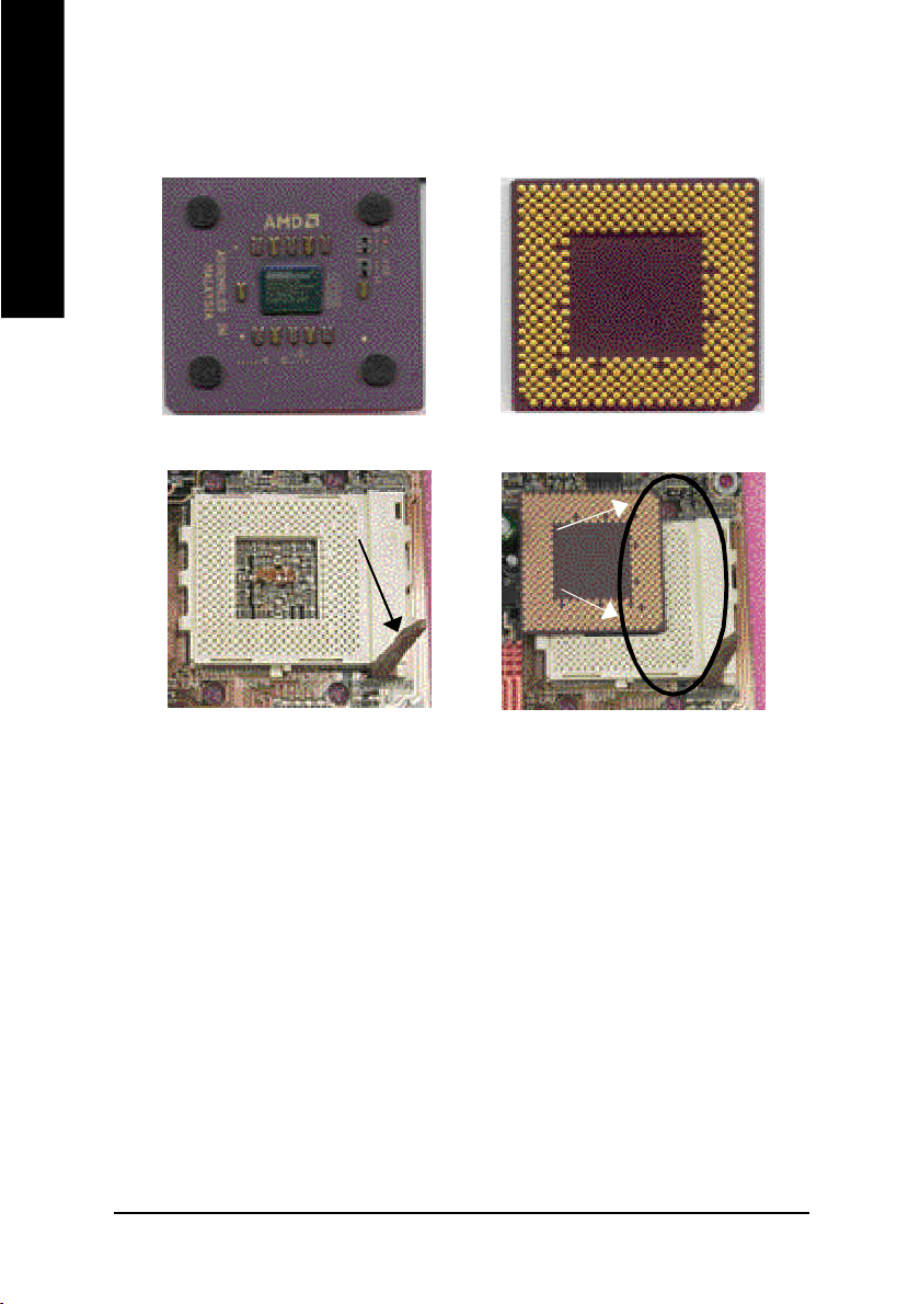
Step1-2: CPU Installation
English
CPU Top View
CPU Bottom View
Socket Actuation Lever
Pin1 indicator
1. Pull up the CPU socket lever
and up to 90-degree angle.
2. Locate Pin 1 in the socket and look
for a (golden) cut edge on the CPU
upper corner. Then insert the CPU
into the socket.
M Please make sure the CPU type is supported by the motherboard.
M If you do not match the CPU socket Pin 1 and CPU cut edge well, it will cause
improper installation. Please change the insert orientation.
- 10 -GA-7VKMLE Motherboard
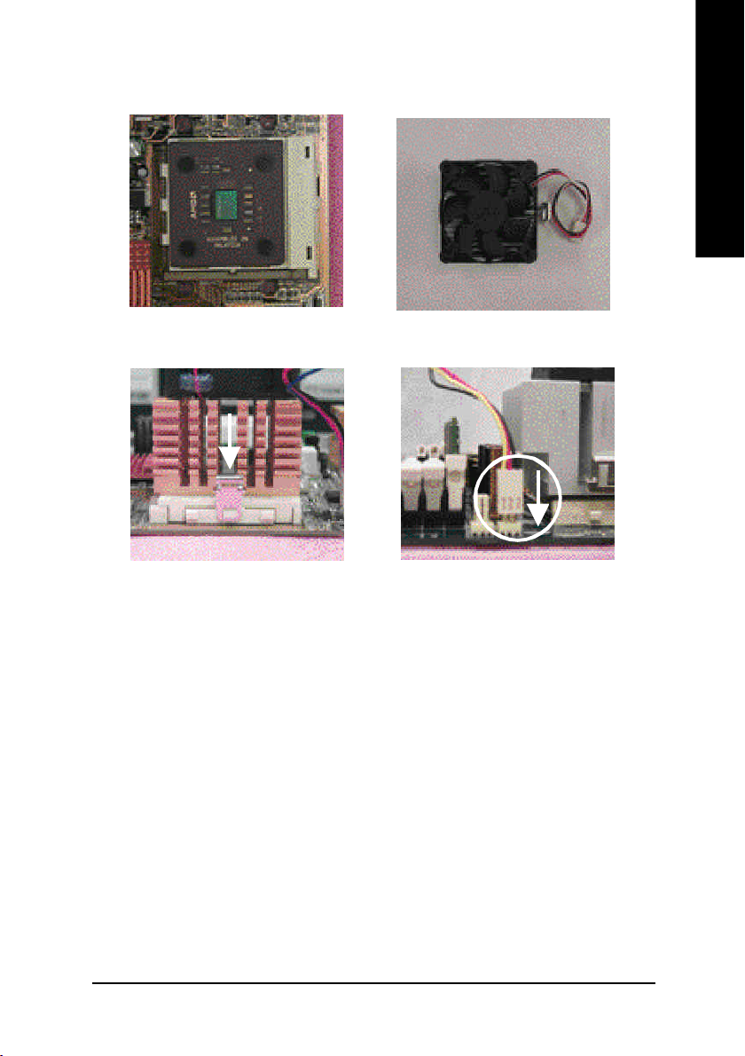
Step1-3: CPU Cooling Fan Installation
English
1.Press down the CPU socket
lever and finish CPU installation.
3.Fasten the cooling fan supporting-base
onto the CPU socket on the main-
board.
2.Use qualified fan approved by AMD.
4.Make sure the CPU fan is plugged to
the CPU fan connector, tha n install
complete.
MPlease use AMD approved cooling fan.
MWe recommend you to apply the thermal paste to provide better heat
conduction between your CPU and cooling fan.
MMake sure the CPU fan power cable is plugged in to the CPU fan connector,
this completes the installation.
MPlease refer to CPU cooling fan user's manual for more detail installation
procedure.
Hardware Installation Process- 11 -
Step 2: Install memory modules
English
cally detects memory type and size. To install the memory module , just push it vertically into the
DIMM Slot. The DIMM module can only fit in one direction due to the notch. Memory size can vary
between sockets.
Total Memory Sizes With Unbuffered DDR DIMM
Devices used on DIMM 1 DIMMx64/x72 2 DIMMsx64/x72
64 Mbit (2Mx8x4 banks) 128 MBytes 256 MBytes
64 Mbit (1Mx16x4 banks) 64 MBytes 128 MBytes
128 Mbit(4Mx8x4 banks) 256 MBytes 512 MBytes
128 Mbit(2Mx16x4 banks) 128 MBytes 256 MBytes
256 Mbit(8Mx8x4 banks) 512 MBytes 1 GBytes
256 Mbit(4Mx16x4 banks) 256 MBytes 512 MBytes
512 Mbit(8Mx16x4 banks) 512 MBytes 1 GBytes
The motherboard has 2 dual inline memory module (DIMM) sockets. The BIOS will automati-
- 12 -GA-7VKMLE Motherboard
DDR
1. The DIMM slot has a notch, so the DIMM
memory module can only fit in one direction.
2. Insert the DIMM memory module verticallyinto the
DIMM slot. Then push it down.
3. Close the plastic clip at both edges of theDIMM slots
to lock the DIMM module.
Reverse the installation steps when you wish to
remove the DIMM module.
DDR Introduction
Established on the existing SDRAM industry infrastructure, DDR (Double Data Rate) memory
is a high performance and cost-effective solution that allows easy adoption for memory vendors,
OEMs and system integrators.
DDR memory is a sensible evolutionary solution for the PC industry that builds on the existing
SDRAM infrastructure, yet makes awesome advances in solving the system performance bottle-
neck by doubling the memory bandwidth. DDR SDRAM will offer a superior solution and migration
path from existing SDRAM designs due to its availability, pricing and overall market support. PC2100
DDR memory (DDR266) doubles the data rate through reading and writing at both the rising and
falling edge of the clock, achieving data bandwidth 2X greater than PC133 when running with the
same DRAM clock frequency. With peak bandwidth of 2.1GB per second, DDR memory enables
system OEMs to build high performance and low latency DRAM subsystems that are suitable for
servers, workstations, high-end PC's and value desktop SMA systems. With a core voltage of only
2.5 Volts compared to conventional SDRAM's 3.3 volts, DDR memory is a compelling solution for
small form factor desktops and notebook applications.
English
M When RAM_LED is ON, do not install/remove DDR from socket.
M Please note that the DIMM module can only fit in one direction due to the one
notches. Wrong orientation will cause improper installation. Please change
the insert orientation.
Hardware Installation Process- 13 -
Step 3: Install expansion cards
1. Read the related expansion card's instruction document before install the expansion card into
English
2. Remove your computer's chassis cover, screws and slot bracket from the computer.
3. Press the expansion card firmly into expansion slot in motherboard.
4. Be sure the metal contacts on the card are indeed seated in the slot.
5. Replace the screw to secure the slot bracket of the expansion card.
6. Replace your computer's chassis cover.
7. Power on the computer, if necessary, setup BIOS utility of expansion card from BIOS.
8. Install related driver from the operating system
the computer.
- 14 -GA-7VKMLE Motherboard
Step 4: Connect ribbon cables, cabinet wires, and power
supply
Step 4-1: I/O Back Panel Introduction
English
u
v w
u PS/2 Keyboard and PS/2 Mouse Connector
PS/2 Mouse Connector
(6 pin Female)
PS/2 Keyboard Connector
(6 pin Female)
ØThis connector supports standard PS/2 keyboard
and PS/2 mouse.
v USB & LAN Connector
Ø Before you connect your device(s) into USB
connector(s), please make sure your device(s)
LAN
USB 1
USB 0
such as USB keyboard,mouse, scanner, zip,
speaker..etc. Have a standard USB interface.
Also make sure your OS supports USB
controller. If your OS does not support USB
controller, please contact OS vendor for possible
patch or driver upgrade. For more information
please contact your OS or device(s) vendors.
x
y
Hardware Installation Process- 15 -
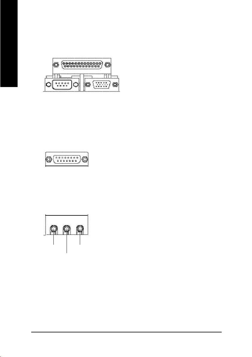
w Parallel Port and VGA Port/COMA Port
English
x Game /MIDI Ports
y Audio Connectors
Parallel Port
(25 pin Female)
COMA
Serial Port
(9 pin Male)
Joystick / MIDI (15 pin Female)
Line Out
MIC In
Line In
VGA
VGA Port
(15 pin Female)
ØThis mainboard sutports 1 standard COM port,
1 VGA port and 1 LPT port. Device like printer
can be connected to LPT port ; mouse and
modem etc can be connected to COM port.
ØThis connector supports joystick, MIDI key
board and other relate audio devices.
ØAfter install onboard audio driver, you may
connect speaker to Line Out jack, micro phone
to MIC In jack. Device like CD-ROM, walkman
etc can be connected to Line-In jack.
- 16 -GA-7VKMLE Motherboard
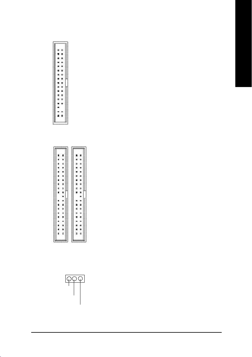
Step 4-2: Connectors Introduction
10
1 3
7
English
4
5
11
13
9
1) CPU_FAN 9) BAT
2) SYS_FAN 10) F_AUDIO
3) ATX 11) CD_IN
4) FDD 12) F_USB1
5) IDE1/IDE2 13) COMB
6) PWR_LED
7) RAM_LED
8) F_PANEL
12
2
8
6
Hardware Installation Process- 17 -

1) CPU_FAN (CPU FAN Connector)
English
1
GND Sense
+12V
Ø Please note, a proper installation of the CPU
cooler is essential to prevent the CPU from run
ning under abnormal condition or damaged by
overheating.The CPU fan connector supports
Max. current up to 600mA .
2) SYS_FAN (System FAN Connector)
GND
1
+12V
Sense
3) ATX (ATX Power)
3.3V
-12V
GND
PS-ON(Soft On/Off)
GND
GND
GND
-5V
VC C
VC C
3.3V
1
3.3V
VC C
Ø This connector allows you to link with the
cooling fan on the system case to lower the
system temperature.
Ø AC power cord should only be connected to
your power supply unit after ATX power cable
and other related devices are firmly connected
to the mainboard.
GND
GND
VC C
GND
Power Good
5V SB (Stand by +5V)
+12V
20
- 18 -GA-7VKMLE Motherboard
4) FDD (Floppy Connector)
Ø Please connect the floppy driver ribbon cables
to FDD. It supports 360K,1.2M,720K,1.44M
and 2.88M bytes floppy disk types.
The rad stripe of the ribbn cable must be the
same side with the Pin1.
1
5) IDE1/IDE2 [IDE1 (Primary), IDE2(Secondary) Connector]
Ø Important Notice:
Please connect first harddisk to IDE1 and
connect CDROM to IDE2.
The rad stripe of the ribbn cable must be the
same side with the Pin1.
English
IDE1
6 ) PWR_LED
IDE2
1
1
MPD+
MPD-
1
Ø PWR_LED is connect with the system power
indicator to indicate whether the system is
on/off. It wi ll blink when the system enters
suspend mode. If you use dual color LED,
power LED will turn to anothe r color.
MPD-
Hardware Installation Process- 19 -
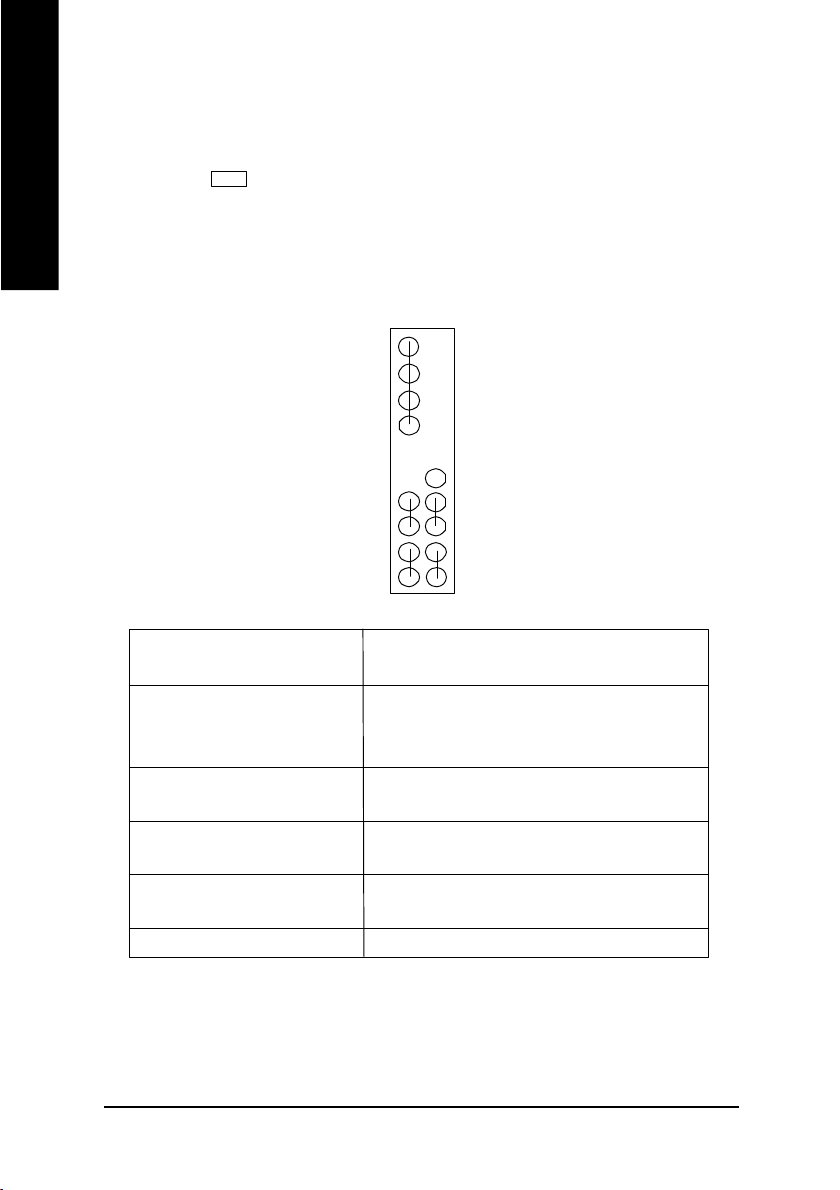
7) RAM_LED
English
8) F_PANEL (2x10 pins Connector)
Ø Do not remove memory modules while
DIMM LED is on. It might cause short or
other unexpected damages due to the 2.5V stand
+
HD (IDE Hard Disk Active LED) Pin 1: LED anode(+)
SPK (Speaker Connector) Pin 1: VCC(+)
RES (Reset Switch) Open: Normal Operation
PW (Soft Power Connector) Open: Normal Operation
MSG(Message LED/Power/ Pin 1: LED anode(+)
Sleep LED) Pin 2: LED cathode(-)
N C N C
-
SPK-
SPK+
PW-
1
PW+
MSG-
1
MSG+
Pin 2: LED cathode(-)
Pin 2- Pin 3: NC
Pin 4: Data(-)
Close: Reset Hardware System
Close: Power On/Off
by voltage. Remove memory modules only
when AC Power cord is disconnected.
19
1
N C
1
RES+
RESHD-
1
HD+
2201
Ø Please connect the power LED, PC speaker, reset switch and power switch etc of your chassis
front panel to the F_PANEL connector according to the pin assignment above.
- 20 -GA-7VKMLE Motherboard
 Loading...