

Gigabyte GA-7VAXP ULTRA, GA-7VAXP-A ULTRA, GA-SINXP1394, GA-8SQ800 ULTRA, GA-8SQ800 ULTRA2 User Manual
...
GC-SATA
Item Checklist
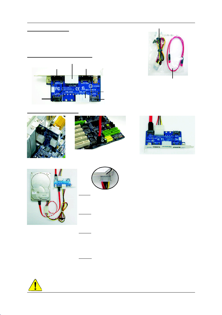
þ GC-SATA Card x 1
þ Power Cable & SATA Cable x 1
GC-SATA Card Layout
SATA-PWR
SATA-CON2
S_ATA2
SATA-CON1
Cable Installation
Power Cable
SATA Cable
PWR CON1
S_ATA1
Step 1
Step 4
S_ATA1+ PWR CON1 only for SATA-PWR+ SATA-CON1
S_ATA2+ PWR CON1 only for SATA-PWR+ SATA-CON2
12MD-SATA00-2001
Step 2
Step 3
Step 5
Step 1:
Please insert and fix the GC-SATA Card in the back panel of the
case.
Step 2: (Internal cable install)
Connect the SATA Cable into the SATA_1 connector on the
Motherboard.
Step 3: (Internal cable install)
Connect the other side of SATA cable into the SATA_1
connector on the GC-SATA Card. And connect the power supply
connector at PWR CON1 on the GC-SATA Card.
Step 4: (External cable install)
Connect both the SATA HDD and the GC-SATA card with the same
power cable in bundle. (Connector : SATA-PWR to HDD SATA-PWR
or 1-4 power connector--see Step 5)
- 1 -
清點附件
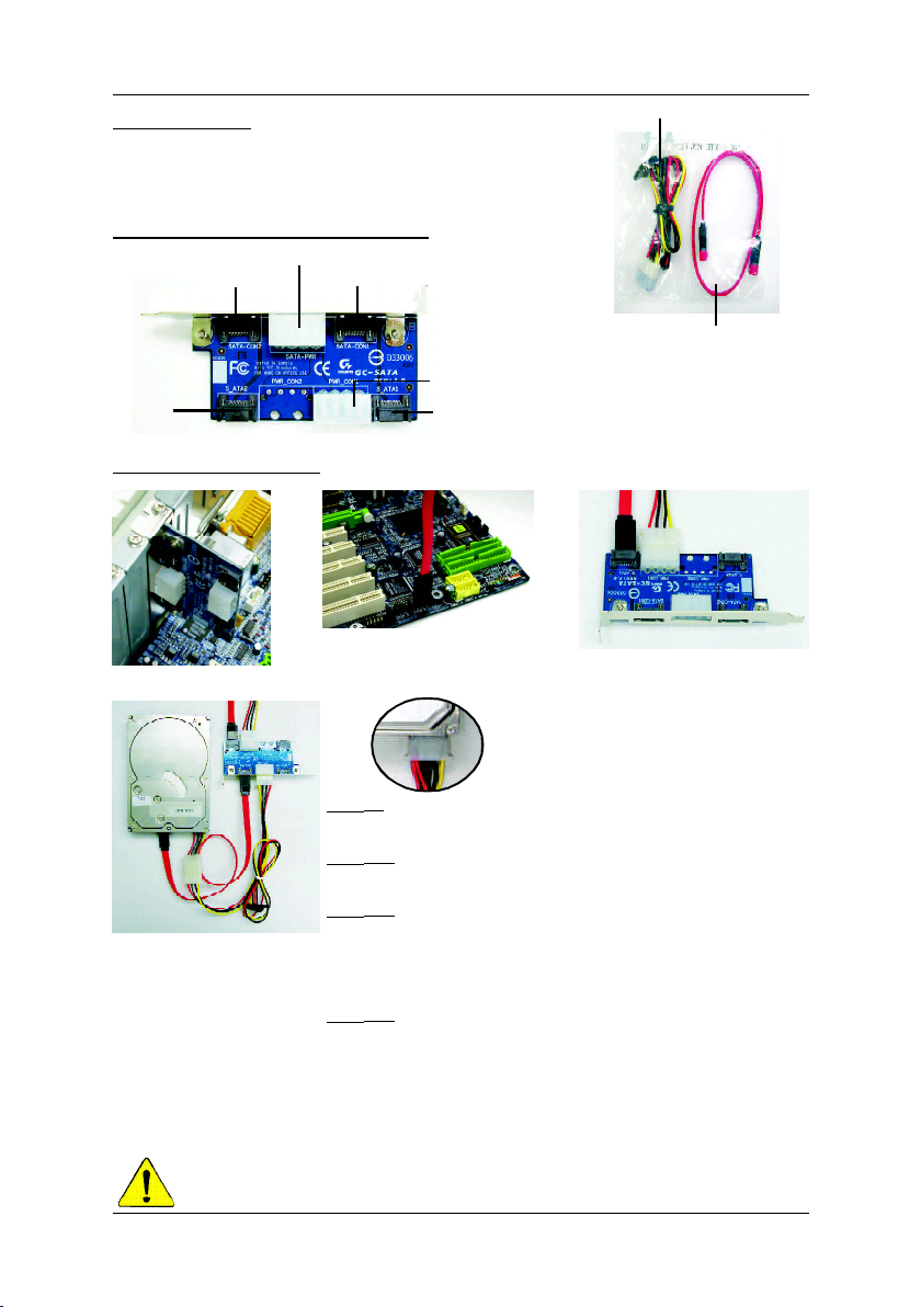
þ GC-SATA Card x 1
þ Power Cable & SATA Cable x 1
GC-SATA Card Layout 圖
SATA-PWR
SATA-CON2
S_ATA2
SATA-CON1
排線安裝方式
GC-SATA
Power Cable
SATA Cable
PWR CON1
S_ATA1
步驟 2
步驟 1
步驟 5
步驟 1 :
先將 G C - SA TA 卡鎖住固定在電腦機殼背板上.
步驟 2: (內建排線安裝)
將 S ATA Ca ble 的一端插在內建主機板S ATA _1 的插座上.
步驟 3: (內建排線安裝)
步驟 4
S_ATA1+ PWR CON1 只對應於 SATA-PWR+ SATA-CON1
S_ATA2+ PWR CON1 只對應於 SATA-PWR+ SATA-CON2
再將 SATA Cable 的另一端插在 GC-SATA 卡上的 SATA_1
的插座上.並接上電源供應器之接頭在GC - SA TA 卡上
PWR CON1 的位置.
步驟 4: (外接排線安裝)
將 Po wer C able 的一端插在 GC -S AT A 卡上的 SA TA-PWR
的插座上. 另一端接上有支援 SATA 功能硬碟之 S A T APWR 接頭( 或接 1 對 4 舊式電源接頭-- 見步驟5) 上. 再
將 SATA C able 接在卡上 SATA-CO N1 及硬碟的SA TA-CON
接頭.
- 2 -
步驟 3
12MD-SATA00-2001
 Loading...