

Page 1

5AX
USER'S MANUAL
¯ Support Intel Pentium, MMX, Cyrix/IBM 6x86MX, M2, AMD K5, K6,
K6-2 & IDT C6 CPUs.
¯ Support auto detect CPU Voltage.
¯ Support Parity check or Ecc Function.
¯ Support Fully AGP 1.0 Specification.
¯ Support switching mode Voltage regulator on Board.
¯ Support 66/75/83 MHz and 100MHz are optional.
¯ Support Modem Ring On (COM B).
¯ Support Wake on Lan
than 600 mA)
¯ Thermal Protection
Pentium
.
Processor PCI - ISA BUS MAINBOARD
REV. 1.0 Second Edition
(The ATX power supply supports larger
Release Date 98.07.21
R-10-02-080721
Page 2

Page 3

5AX
The author assumes no responsibility for any errors or omissions which may
appear in this document nor does it make a commitment to update the information
contained herein.
¯THIRD-PARTY BRANDS AND NAMES ARE THE PROPERTY OF THEIR
RESPECTIVE OWNERS.
JULY 21, 1998 Taipei, Taiwan
1
Page 4
Quick Installation Guide
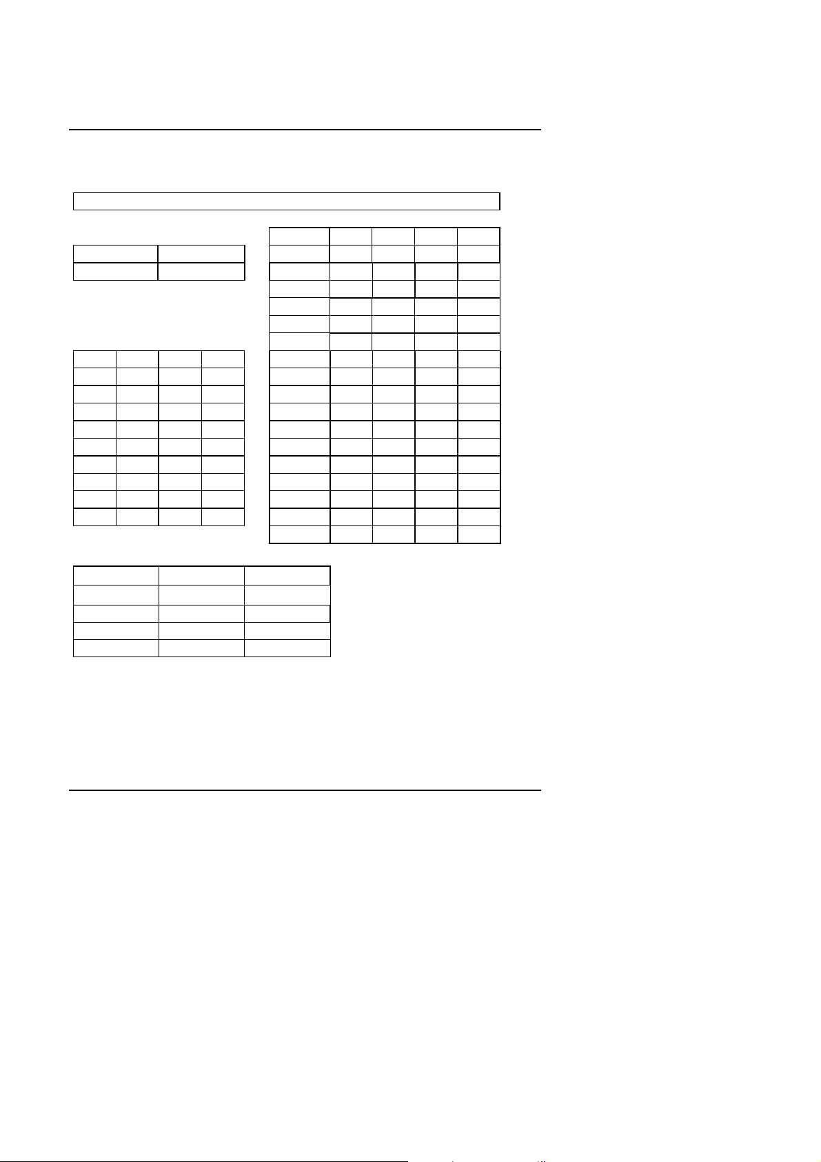
I. CPU Jumper Setting Table:
SW: CPU INT./ EXT. FREQ. RATIO
t
SW 4 5 6 7
O ON AUTO X X X O
X OFF 2.0 V X X X X
2.1 V X X O X
2.2 V X O X X
2.3 V X O O X
2.4 V O X X X
SW 2 3 8 2.5 V O X O X
x 1.5 X X X 2.6 V O O X X
x 2 O X X 2.7 V O O O X
x 2.5 O O X 2.8 V X X X O
x 3 X O X 2.9 V X X O O
x 3.5 X X X 3.0 V X O X O
x 4 O X O 3.1 V X O O O
x 4.5 O O O 3.2 V O X X O
x 5 X O O 3.3 V O X O O
x 5.5 X X O 3.4 V O O X O
3.5 V O O O O
MHz SW1 SW4
66 X
2-3
75 X 1-2
83 O 2-3
100 O 1-2
2
Page 5

5AX
II. Quick Installation Guide:
CPU
1. Pentium
2. Pentium
3. Pentium
4. Pentium
Processor 100 MHz
Processor 133 MHz
Processor 166 MHz
Processor 200 MHz
5. Intel MMX-166MHz
6. Intel MMX-200MHz
7. Intel MMX-233MHz
8. P54CT-166 MHz
9. P54CTB-166 MHz
10. P54CTB-200 MHz
11. AMDK5-PR133
12. AMDK5-PR166
13. AMD-K6/166 (2.9V)
SW1 SW2 SW3 SW4 SW5 SW6 SW7 SW8 JP4
OFF OFF OFF OFF OFF OFF ON OFF 2-3
OFF ON OFF OFF OFF OFF ON OFF 2-3
OFF ON ON OFF OFF OFF ON OFF 2-3
OFF OFF ON OFF OFF OFF ON OFF 2-3
OFF ON ON OFF OFF OFF ON OFF 2-3
OFF OFF ON OFF OFF OFF ON OFF 2-3
OFF OFF OFF OFF OFF OFF ON OFF 2-3
OFF ON ON OFF OFF OFF ON OFF 2-3
OFF ON ON OFF OFF OFF ON OFF 2-3
OFF OFF ON OFF OFF OFF ON OFF 2-3
OFF ON OFF OFF OFF OFF ON OFF 2-3
OFF ON ON OFF OFF OFF ON OFF 2-3
OFF ON ON OFF OFF ON ON OFF 2-3
14. AMD-K6/200 (2.9V)
15. AMD-K6/233 (3.2V)
16. AMD-K6/266 (66*4 2.2V)
AMD-K6-2/266 (66*4 2.2V)
17. AMD-K6/266 (100*2.5
2.2V)
18. AMD-K6/300 (66*4.5 2.2V)
OFF OFF ON OFF OFF ON ON OFF 2-3
OFF OFF OFF ON OFF OFF ON OFF 2-3
OFF ON OFF OFF ON OFF OFF ON 2-3
ON ON ON OFF ON OFF OFF OFF 1-2
OFF ON ON OFF ON OFF OFF ON 2-3
3
Page 6

Quick Installation Guide
19. AMD-K6/300 (100*3 2.2V)
AMD-K6-2/300 (100*3
2.2V)
CPU
20. Cyrix/IBM 6x86-150MHzPR200+ (75*2)
21. Cyrix/IBM 6x86L-PR166+
(2.8V)
22. Cyrix/IBM 6x86MX-PR200+
(75*2 2.9V)
23. Cyrix/IBM 6x86MX-PR166
(66*2 2.9V)
24. Cyrix/IBM 6x86MX-PR200
(66*2.5 2.9V)
25. Cyrix/IBM 6x86MX-PR200
(75*2 2.9V)
26. Cyrix/IBM 6x86MX-PR233
(66*3 2.9V)
27. Cyrix/IBM 6x86MX-PR233
(75*2.5 2.9V)
28. Cyrix/IBM 6x86MX-PR233
(83*2 2.9V)
29. Cyrix/IBM 6x86MX-PR266
(66*3.5 2.9V)
30. Cyrix/IBM 6x86MX-PR266
(75*3 2.9V)
31. Cyrix/IBM 6x86MX-PR266
(83*2.5 2.9V)
32. Cyrix M2-PR300
(66*3.5 2.9V)
33. IDT C6-200 (66*3 3.52V)
34. IDT C6-225 (75*3 3.52V)
35. IDT C6-266 (66*4 3.52V)
ON OFF ON OFF ON OFF OFF OFF 1-2
SW1 SW2 SW3 SW4 SW5 SW6 SW7 SW8 JP4
OFF ON OFF OFF OFF OFF ON OFF 1-2
OFF ON OFF OFF OFF OFF ON OFF 2-3
OFF ON OFF OFF OFF ON ON OFF 1-2
OFF ON OFF OFF OFF ON ON OFF 2-3
OFF ON ON OFF OFF ON ON OFF 2-3
OFF ON OFF OFF OFF ON ON OFF
OFF OFF ON OFF OFF ON ON OFF 2-3
OFF ON ON OFF OFF ON ON OFF 1-2
ON ON OFF OFF OFF ON ON OFF 2-3
OFF OFF OFF OFF OFF ON ON OFF 2-3
OFF OFF ON OFF OFF ON ON OFF 1-2
ON ON ON OFF OFF ON ON OFF 2-3
OFF OFF OFF OFF OFF ON ON OFF 1-2
OFF OFF ON OFF OFF OFF ON OFF 2-3
OFF OFF ON OFF OFF OFF ON OFF 1-2
OFF ON OFF OFF OFF OFF ON ON 2-3
1-2
4
Page 7
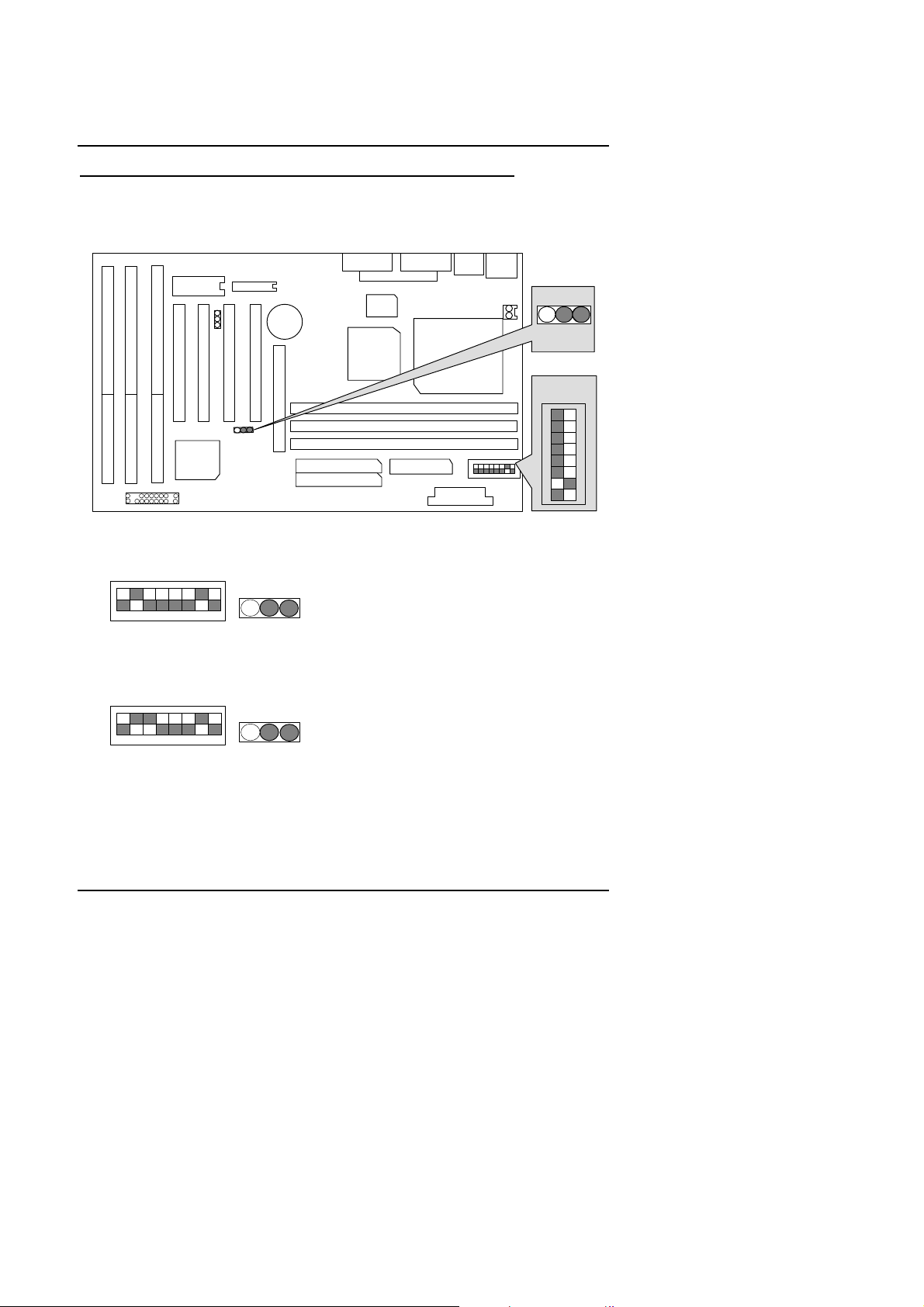
5AX
JP8
1234567
8
ON
sw
sw
sw
¬
Note: If Cyrix 6x86 is being used, please check the CPU Date Code after 605.
1. Pentium Processor 100 MHz
1
1
JP4
1 1
JP5JP4
2. Pentium Processor 133 MHz
1ON
OFF
1 2 3 4 5 6 7 8
JP4
3. Pentium Processor 166 MHz
ON
OFF
1 2 3 4 5 6 7 8
1
JP4
1 1
1 1
JP7JP6
0
CPU
1
JP10
1
1
JP4
S1
4. Pentium Processor 200 MHz
5
Page 8

Quick Installation Guide
sw
ON
OFF
1 2 3 4 5 6 7 8
1
JP4
6
Page 9

5AX
sw
sw
sw
sw
sw
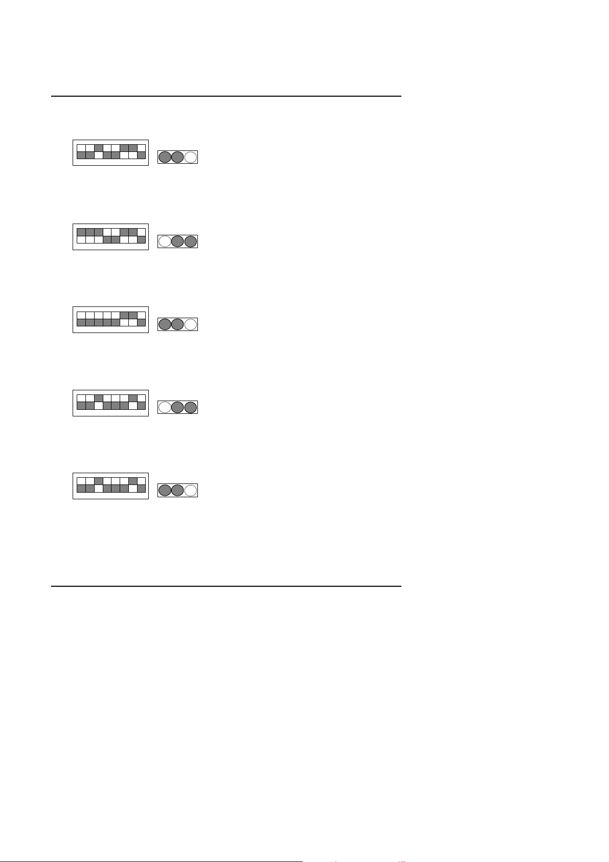
5. Intel MMX-166 MHz
ON
OFF
1 2 3 4 5 6 7 8
6. Intel MMX-200 MHz
ON
OFF
1 2 3 4 5 6 7 8
7. Intel MMX-233 MHz
ON
OFF
1 2 3 4 5 6 7 8
8. P54CT-166 MHz
ON
OFF
1 2 3 4 5 6 7 8
1
JP4
1
JP4
1
JP4
1
JP4
1
9. P54CTB-166 MHz
ON
OFF
1 2 3 4 5 6 7 8
1
JP4
7
Page 10

10. P54CTB-200 MHz
sw
sw
sw
sw
sw
Quick Installation Guide
ON
OFF
1 2 3 4 5 6 7 8
11. AMDK5-PR133
ON
OFF
1 2 3 4 5 6 7 8
12. AMDK5-PR166
ON
OFF
1 2 3 4 5 6 7 8
13. AMD-K6/166 (2.9V)
ON
OFF
1 2 3 4 5 6 7 8
1
JP4
1
JP4
1
JP4
1
JP4
14. AMD-K6/200 (2.9V)
ON
OFF
1 2 3 4 5 6 7 8
1
JP4
8
Page 11

5AX
sw
sw
sw
sw
sw
15. AMD-K6/233 (3.2V)
ON
OFF
1 2 3 4 5 6 7 8
1
JP4
16. AMD-K6/266 (2.2V 66*4); AMD-K6-2 266 (2.2V 66*4)
ON
OFF
1 2 3 4 5 6 7 8
1
JP4
17. AMD-K6/266 (2.2V 100*2.5)
ON
OFF
1 2 3 4 5 6 7 8
1
JP4
18. AMD-K6/300 (2.2V 66*4.5)
ON
OFF
1 2 3 4 5 6 7 8
1
JP4
19. AMD-K6/300 (2.2V 100*3); AMD-K6-2 300 (2.2V 100*3)
ON
OFF
1 2 3 4 5 6 7 8
1
JP4
9
Page 12

20. Cyrix /IBM 6x86-150 MHz-PR200+ (75*2)
sw
sw
sw
sw
sw
Quick Installation Guide
ON
OFF
1 2 3 4 5 6 7 8
1
JP4
21. Cyrix / IBM 6x86L-PR166+ (2.8V)
ON
OFF
1 2 3 4 5 6 7 8
1
JP4
22. Cyrix / IBM 6x86L-PR200+ (75*2 2.9V)
ON
OFF
1 2 3 4 5 6 7 8
1
JP4
23. Cyrix / IBM 6x86MX-PR166 (66x2 2.9V)
ON
OFF
1 2 3 4 5 6 7 8
1
JP4
24. Cyrix / IBM 6x86MX-PR200 (66x2.5 2.9V)
ON
OFF
1 2 3 4 5 6 7 8
1
JP4
10
Page 13

5AX
sw
sw
sw
sw
sw
25. Cyrix / IBM 6x86MX-PR200 (75x2 2.9V)
ON
OFF
1 2 3 4 5 6 7 8
1
JP4
26. Cyrix / IBM 6x86MX-PR200 (66x3 2.9V)
ON
OFF
1 2 3 4 5 6 7 8
1
JP4
27. Cyrix / IBM 6x86MX-PR233 (75x2.5 2.9V)
ON
OFF
1 2 3 4 5 6 7 8
1
JP4
28. Cyrix / IBM 6x86MX-PR233 (83x2 2.9V)
ON
OFF
1 2 3 4 5 6 7 8
1
JP4
29. Cyrix / IBM 6x86MX-PR266 (66x3.5 2.9V)
ON
OFF
1 2 3 4 5 6 7 8
1
JP4
11
Page 14
30. Cyrix / IBM 6x86MX-PR266 (75x3 2.9V)
sw
sw
sw
sw
sw
Quick Installation Guide
ON
OFF
1 2 3 4 5 6 7 8
1
JP4
31. Cyrix / IBM 6x86MX-PR266 (83x2.5 2.9V)
ON
OFF
1 2 3 4 5 6 7 8
1
JP4
32. Cyrix M2-PR300 (66x3.5 2.9V)
ON
OFF
1 2 3 4 5 6 7 8
1
JP4
33. IDT C6-200 (66x3 3.52V)
ON
OFF
1 2 3 4 5 6 7 8
1
JP4
34. IDT C6-225 (75x3 3.52V)
ON
OFF
1 2 3 4 5 6 7 8
1
JP4
12
Page 15

5AX
sw
35. IDT C6-266 (66x4 3.52V)
ON
OFF
1 2 3 4 5 6 7 8
1
JP4
III. Quick Installation Guide of Jumper setting:
SPK : Speaker Connector
1
Pin No.
Function
1
2
3
4
VCC
NC
NC
Data
JP4
JP
JP
RST : Reset Switch
Open :
Normal operation.
Close :
For hardware reset system.
1
1
JP1
CPU
JP
JP
1
S1
JP1
CPU
JP
JP
13
JP4
JP
JP
1
S1
Page 16

PWR LED : Power LED (As a 3 steps ACPI LED)
1
Quick Installation Guide
Pin No.
1
2
3
Function
LED anode (+).
LED cathode (-).
LED cathode (-).
HD : IDE Hard Disk Active LED
1
Pin No.
1
2
Function
LED anode (+)
LED cathode (-)
GN : Green Function Switch
Open :
Normal operation.
Close one time:
For system entering Green
mode
JP4
JP4
JP1
CPU
JP
JP
CPU
CPU
JP1
JP1
1
S1
1
S1
JP
JP
JP
JP
JP
JP
JP
JP
14
JP4
1
S1
Page 17

5AX
Pin No.
Function
GD : Green LED
1
Pin No.
1
2
Function
LED canode (-)
LED athode (+)
SOFT PWR : Power On/Off Switch
1
Two Option :
1. Instant On/Off:Power On/Off
system immediately
2. Delay 4 Seconds:Power. Off
system.Press over 4 Secs
ATX Power Connector
1
11
3,5,7,13,15-17
4,6,19,20
10
12
18
8
9
14
GND
VCC (+5V)
+12V
-12V
-5V
Power Good
5V SB
(Stand by )
PS-ON
(Soft ON/OFF)
JP4
JP4
JP1
CPU
JP
JP
CPU
CPU
JP1
JP1
1
S1
1
S1
1
S1
JP
JP
JP
JP
JP
JP
JP
JP
JP
JP
15
Page 18

JP9 : CPU Cooling Fan Power Connector
Pin No.
Function
+5V
GND
Signal
321
1
Pin No.
1
2
Function
+12V
GND
JP4
JP8: Wake On Lan
1
JP4
Quick Installation Guide
JP1
CPU
JP
JP
CPU
JP1
1
S1
1
S1
JP
JP
JP
JP
JP
JP
LPT : LPT PORT
16
JP4
JP1
CPU
JP
JP
JP
JP
1
S1
Page 19

5AX
CN4 : USB Port
CN5 : COM B
JP4
JP4
JP1
CPU
JP
JP
CPU
JP1
1
S1
1
S1
JP
JP
JP
JP
JP
JP
CN6 : COM A
17
JP4
JP1
CPU
JP
JP
JP
JP
1
S1
Page 20

JP11 : PS/2 Mouse / Keyboard Connector
Pin No.
Function
123
4
Key Data
VCC (+5V)
GND
PS/2 Mouse
PS/2 Keyboard
Quick Installation Guide
JP1
PS/2 Mouse / Keyboard
NC
5 Key Clock.
6 NC
CN2 : FLOPPY PORT
1
RED LINE
CN1 : For Primary IDE port
1
RED LINE
JP4
JP4
CPU
JP
JP
CPU
CPU
JP1
JP1
1
S1
1
S1
JP
JP
JP
JP
18
JP4
JP
JP
JP
JP
1
S1
Page 21

5AX
CN3 : For Secondary IDE port
1
RED LINE
BT1 : For Battry
+
M Danger of explosion if battery is
incorrectly replaced.
Replace only with the same or
M
equivalent type recommended by
the manufacturer.
Dispose of used batteries
M
according to the manufacturer’s
instructions.
–
JP4
JP4
JP1
CPU
JP
JP
CPU
JP1
1
S1
1
S1
JP
JP
JP
JP
JP
JP
19
Page 22

Quick Installation Guide
III. Top Performance Test Setting:
Users have to modify the value for each item in chipset features as follow
for top performance setting.
**
Each value of items as above depends on your hardware configuration : CPU ,
SDRAM , Cards , etc.
Please modify each value of items If your system does not work properly.
20
Page 23

5AX
PERFORMANCE LIST
The following list of performance data is the testing results of some popular
benchmark testing programs.
These data are just referred by users, and there is no responsibility for different
testing data values gotten by users. (The different Hardware & Software
configuration will result in different benchmark testing results.)
• CPU
Pentium Processor MMX-233 MHz , Cyrix 6x86M2PR300 , AMD K6-2 300
• DRAM (128 × 1) MB SDRAM (LGS GM72N66841CT7J)
• CACHE SIZE 512 KB
• DISPLAY GA-600 (4MB SGRAM)
• STORAGE Onboard IDE (IBM DHEA-36451)
• O.S. Windows® NT 4.0
• DRIVER
Processor
Winbench98
CPU mark32
FPU Winmark
Business Disk
Hi-End Disk
Business Graphics
Hi-End Graphics
Display Driver at 1024 x 768 x 256 colors x 75Hz.
ALi Bus Master IDE Driver
Intel-MMX 233MHz
(66x3.5)
AMD K6-2 300
(100x3)
Cyrix M-2 PR300
467 756 478
912 979 534
1760 1840 1820
4160 4550 4450
105 153 139
109 156 150
Winstone98
Business
Hi-End
22.5
29.1 25.9
23.8 29.6 26.7
(66x3.5 )
21
Page 24

 Loading...