

Page 1

FCC Compliance Statement:
This equipment has been tested and found to
comply with limits for a Class B digital device,
pursuant to Part 15 of the FCC rules. These
limits are designed to provide reasonable
protection against harmful interference in
residential installations. This equipment
generates, uses, and can radiate radio
frequency energy, and if not installed and used
in accordance with the instructions, may cause
harmful interference to radio communications.
However, there is no guarantee that interference
will not occur in a particular installation. If this
equipment does cause interference to radio or
television equipment reception, which can be
determined by turning the equipment off and on, the user is encouraged to try to
correct the interference by one or more of the following measures:
-Reorient or relocate the receiving antenna
-Move the equipment away from the receiver
-Plug the equipment into an outlet on a circuit different from that to which
the receiver is connected
-Consult the dealer or an experienced radio/television technician for
additional suggestions
You are cautioned that any change or modifications to the equipment not
expressly approve by the party responsible for compliance could void Your
authority to operate such equipment.
This device complies with Part 15 of the FCC Rules. Operation is subjected to
the following two conditions 1) this device may not cause harmful interference
and 2) this device must accept any interference received, including interference
that may cause undesired operation.
DECLARATION OF CONFORMITY
Per FCC Part 2 Section 2. 1077(a)
Responsible Party Name: G.B.T. INC.
Address: 18305 Vall ey Blvd., Suite #A
LA Puent, CA 91744
Phone/Fax No: (818) 85 4-9338/ (818) 854-9339
hereby declares that the product
Product Name:
Model Number:
Mother Board
Conforms to the following specifications:
FCC Part 15, Subpart B, Section 15.107(a) and Sect ion 15.109(a),
Class B Digital Device
Supplementary Information:
This device complies with part 15 of the F CC Rules. Operation is subject to the
following two condit ions: (1) This device may not caus e ha rmful
and (2) this device must accept any inference received, including
that may cause undesired operation.
Representative Person's Name: ERIC LU
Signature:
Date: May. 4, 2001
Eric Lu
GA-6OXET
Page 2

Declaration of Conformity
We, Manufacturer/Importer
(full address)
G.B.T. Technology Träding GMbH
Ausschlager Weg 41, 1F, 20537 Hamburg, Germany
declare that the product
( description of the apparatus, system, installation to which it refer s)
Mother Board
GA-6OXET
is in conformity with
(reference to the specification under which conformity is declared)
in accordance with 89/336 EEC-EMC Directive
EN 55011
Limits and methods of measurement
EN 61000-3-2*
Disturbances in supply systems caused
of radio disturbance characteristics of
EN60555-2
by household appliances and sim ilar
industrial, scientific and medical (ISM electrical equipment “Harmoni c s”
high frequency equipment
EN55013
Limits and methods of measurement
EN61000-3-3*
Disturbances in supply systems caused
of radio disturbance characteristics of
EN60555-3
by household appliances and sim ilar
broadcast receivers and associated electrical equipment “V oltage fl uc tuations”
equipment
EN 55014
Limits and methods of measurement
EN 50081-1
Generic emission standard Part 1:
of radio disturbance characteristics of
Residual, commercial and light industry
household electric al appliances,
portable tools and similar elec trical
EN 50082-1
Generic immunity standar d P ar t 1:
apparatus Residual, commercial and light industry
EN 55015
Limits and methods of measurement
EN 55081-2
Generic emission standard Part 2:
of radio disturbance characteristics of Industrial env ironment
fluorescent lamps and lumi nar ies
EN 55020
Immuni ty from r adio interference of
EN 55082-2
Generic immunity standar d P ar t 2:
broadcast receivers and associated Industrial environment
equipment
EN 55022
Limits and methods of measurement
ENV 55104
Immunity requir ements for household
of radio disturbance characteristics of appliances tools and simi lar apparatus
inform ation technology equipment
DIN VDE 0855
Cabled distribut ion systems; Equipment
EN 50091- 2
EMC requirements for uninterruptible
part 10
for receiving and/or
distribution
from power systems (UPS)
part 12
sound and televi si on signals
CE marking
(EC conform ity marking)
The manufacturer also declares the conformity of above mentioned product
with the actual required safet y standards in acco rdance with L V D 73/23 EEC
EN 60065
Safety requi rements for mains operated
EN 60950
Safety for information technology equipment
electronic and r elated apparatus for including elec trical business equipment
household and simil ar gener al use
EN 60335
Safety of household and similar
EN 50091-1
General and Safety requirements for
electrical appliances uninterruptible power systems (UPS)
Manufacturer/Importer
Signature
:
Rex Lin
(Stamp)
Date: May. 4, 2001 Name : Rex Lin
Page 3

6OXET Series
Socket 370 Processor Motherboard
USER'S MANUAL
Socket 370 Processor Motherboard
REV. 0.3 First Edition
R-03-01-010510
Page 4

Page 5

How This Manual Is Organized
This manual is divided into the following sections:
1) Revision History
Manual revision information
2) Item Checklist
Product item list
3) Features
Product information & specification
4) Hardware Setup
Instructions on setting up the motherboard
5) Performance & Block Diagram
Product performance & block diagram
6) Suspend to RAM & Dual BIOS
Instructions STR installation & Dual BIOS
7) Four Speaker & SPDIF
Four Speaker & SPDIF introduction
8) @ BIOS™ & EasyTune
III
™
@ BIOS
™
& EasyTune
III
™
introduction
9) BIOS Setup
Instructions on setting up the BIOS
software
10) Appendix
General reference
Page 6

Page 7

Table Of Content
Revision History P.1
Item Checklist P.2
Summary of Features P.3
6OXET Series Motherboard Layout P.5
Installation Guide P.6
Page Index for CPU Speed Setup/Connectors/Panel and Jumper Definition P.12
Performance List P.38
Block Diagram P.39
Suspend to RAM Installation (Optional) P.40
Introduce Dual BIOS (Optional) P.46
Four Speaker & SPDIF Introduction (Optional) P.53
@ BIOSTM Introduction P.58
EasyTune
III
TM
Introduction P.59
Memory Installation P.60
Page Index for BIOS Setup P.61
Appendix P.99
Page 8

6OXET Series Motherboard
1
Revision History
Revision Revision Note Date
0.3 Initial release of the 6OXET Series motherboard user’s
manual.
May.2001
The author assumes no responsibility for any errors or omissions that may appear in this
document nor does the author make a commitment to update the information contained herein.
Third-party brands and names are the property of their respective owners.
May. 10, 2001 Taipei, Taiwan, R.O.C
Page 9

Item Check l i st
2
Item Checklist
;
The 6OXET Series motherboard
;
Cable for IDE / floppy device
;
Diskettes or CD (IUCD) for motherboard driver & utility
;
6OXET Series user’s manual
Page 10

6OXET Series Motherboard
3
Summary Of Features
Form Factor
y
30.5 cm x 21.9 cm ATX SIZE form factor, 4 layers PCB.
Motherboard
y
6OXET series includes 6OXET, 6OXET-C
CPU
y
Socket 370 processor
Supports all new PentiumIII processors (FC-PGA & FC-PGA2
package)
Supports
Celeron processors
in FC-PGA package
Supports
Cyrix processors
in FC-PGA package
Supports 66/100/133MHz system bus frequency
Can’t Support proc essor with Vcore above 1.8V
y
L2 cache in CPU (Depend on CPU)
Chipset
y
Intel FW82815EP-B-Step HOST / AGP / SDRAM
Controller
y
FW82801BA I/O Controller Hub (ICH2X)
Clock Generator
y
ICS94301AF
y
66/100/133 MHz system bus speeds
Memory
y
4 168-pin DIMM sockets (DIMM 4 is optional)
y
Supports PC-100 / PC-133 SDRAM
y
Supports up to 512MB
y
Supports only 3.3V SDRAM DIMM (Over voltage
3.4V/ 3.5V)
I/O Control
y
IT8712F
Slots
y
1 AGP Slot Supports 4X/2X mode & AGP 2.0 compliant
(Over Voltage 1.6/1.7V)
y
6 PCI Slots Supports 33MHz & PCI 2.2 compliant
y
1 CNR (Communication and Networking Riser) Slot
(Optional)
On-Board IDE
y
Supports PIO mode 3, 4, DMA33/ATA66/ATA100 IDE
& ATAPI CD-ROM
y
2 IDE bus master (UDMA 33/ATA 66/ATA100) IDE ports
for up to 4 ATAPI devices
On-Board
Peripherals
y
1 floppy port supports 2 FDD with 360K, 720K, 1.2M,
1.44M and 2.88M bytes
y
1 parallel port supports SPP/EPP/ECP mode
y
2 serial ports (COM A & COM B)
y
4 USB ports
y
1 IrDA connector for IR/CIR
y
1 SCR (Smart Card Reader) connector (Optional)
To be continued…
Page 11

Summary of Features
4
Hardware Monitor
y
CPU/Power Supply/System fan revolution detect
y
CPU temperature detect
y
System voltage detect
y
CPU overheat shutdown detect
y
Support Case Open (Optional)
On-Board Sound
y
Creative CT5880 sound (Optional)
y
AC’97 CODEC
y
Line In/Line Out/Mic In/AUX In (Optional)/CD In/
TEL (Optional)/ SPDIF (Optional)/Game Port/
Four Speaker (Optional)
y
Front Audio (Optional)
y
Front MIC (Optional)
BIOS
y
Licensed AWARD BIOS, 2M bit flash ROM
y
Support Dual BIOS (Optional)
PS/2 Connector
y
PS/2 keyboard interface and PS/2 mouse interface
Additional Features
y
Supports Wake-on-LAN (WOL)
y
Support S_IRQ (Serial IRQ)
y
STR (Suspend-To-RAM) (Optional)
y
Supports Internal / External modem wake up
y
Includes 3 fan power connectors
y
Poly fuse for keyboard over-current protection
y
Support @BIOS™ and EasyTune
III
™
Page 12
6OXET Series Motherboard
5
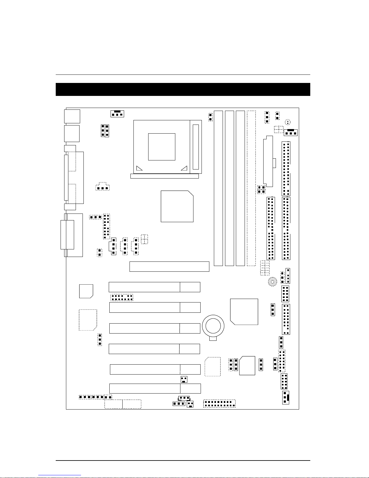
6OXET Motherboard Layout
PCI2
PCI3
ICH2X
FW82801BA
COM B
COM A
LPT
PS/2
PCI4
PCI5
AGP
CNR
6OXET
BAT1
USB
ATX Power
Floppy
IDE2
IDE1
Main
BIOS
Creative
CT5880
BZ1
FW82815EP-
B-Step
DIMM
LED
PCI6
AC97
JP1
JP3
J1
J2
JP4
JP7
JP9
J5
J6
J7
J10
JP12
JP13
J11
JP14
JP15
JP26
CN9
J14
JP20
JP21
J13
JP24
JP22
J12
JP18
JP19
JP23
JP27
Backup
BIOS
J15
JP28
JP31
PCI1
DIMM3
DIMM2
DIMM4
DIMM1
CN13
JP32
JP33
SW1
PGA 370
CPU
AGP_OV
JP2
JP34
JP29
JP30
RAM
_OV
Game & Audio
Page 13

Installation Guide
6
Installation Guide
Getting Started
WARNING!
Computer motherboards and expansion cards contain very delicate Integrated
Circuit (IC) chips. To protect them against damage from static electricity, you
should follow some precautions whenever you work on your computer.
1. Unplug your computer when working on the inside.
2. Use a grounded wrist strap before handling computer components. If you do not have one,
touch both of your hands to a safely grounded object or to a metal object, such as the power
supply case.
3. Hold components by the edges and try not touch the IC chips, leads or connectors, or other
components.
4. Place components on a grounded antistatic pad or on the bag that came with the
components whenever the components are separated from the system.
5. Ensure that the A TX power supply is switched off before you plug in or remove the ATX power
connector on the motherboard.
Installing the motherboard to the chassis…
If the motherboard has mounting holes, but they don’t line up with the holes on the base and there
are no slots to attach the spacers, do not become alarmed you can still attach the spacers to the
mounting holes. Just cut the bottom portion of the spacers (the spacer may be a little hard to cut off,
so be careful of your hands). In this way you can still attach the motherboard to the base without
worrying about short circuits. Sometimes you may need to use the plastic springs to isolate the
screw from the motherboard PCB surface, because the circuit wire may be near by the hole. Be
careful, don’t let the screw contact any printed circuit write or parts on the PCB that are near the
fixing hole, otherwise it may damage the board or cause board malfunctioning.
Page 14
6OXET Series Motherboard
7
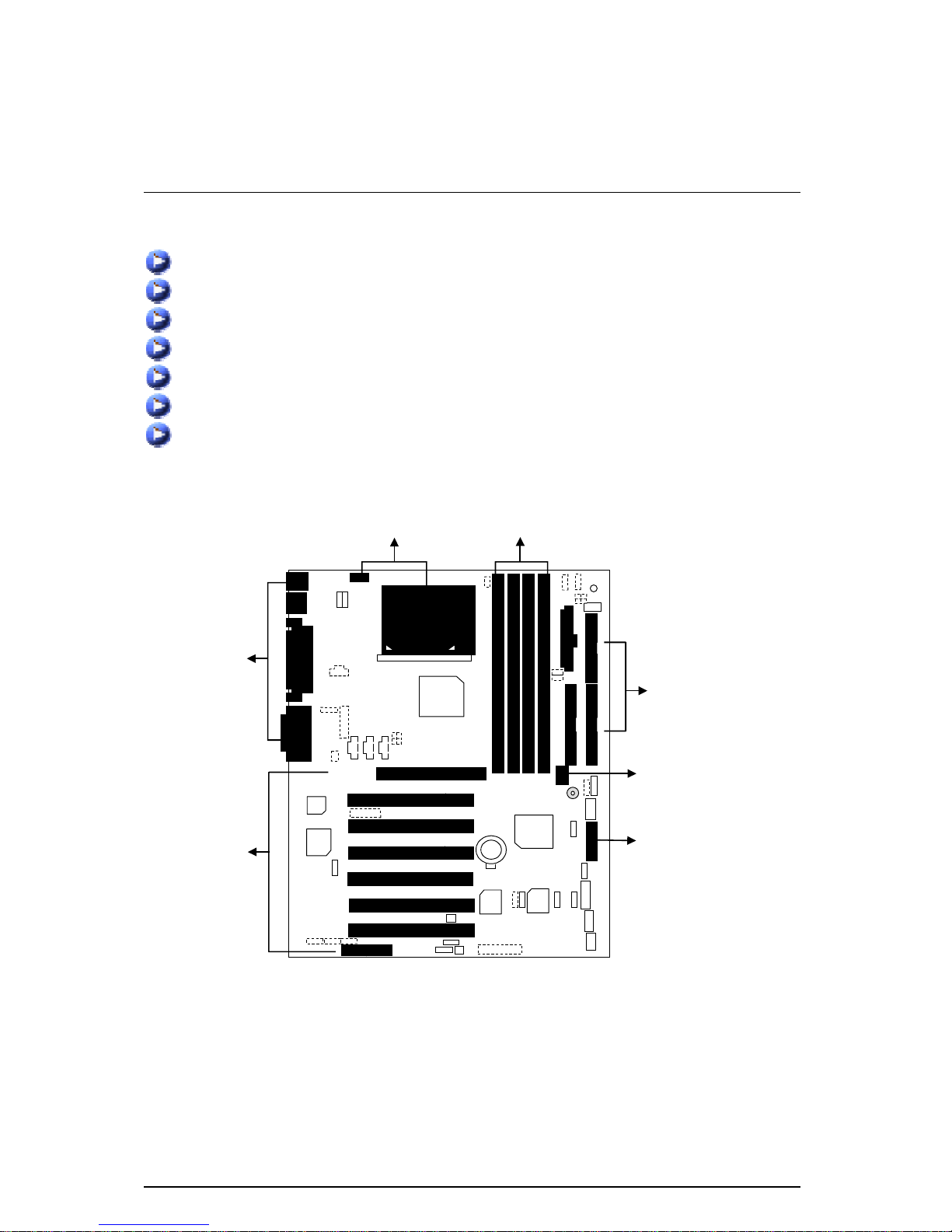
To set up your computer, you must complete the following steps:
Step 1 - Set system jumpers
Step 2- Install the Central Processing Unit (CPU)
Step 3-Install memory modules
Step 4-Install expansion cards
Step 5-Connect ribbon cables, cabinet wires, and power supply
Step 6-Set up BIOS software
Step 7-Install supporting software tools
Step 2
Step 1
Step 3
Step 4
Step 5
Step 5
Step 5
Page 15

Page Index for CPU Speed Setup
8
CPU Speed Setup
The system bus speed is selectable at 66,100,133MHz and Auto. The user can select the system
bus speed by DIP switch
SW1
.
SW1: (Optional)
O : ON, X : OFF
CPU SDRAM 1 2 3 4 5 6
AUTO AUTO X X X X X X
66 100 X X X O O O
100 100 X X X X O O
133 133 X X X O X O
133 100 X X X X X O
Auto Configuration:
CPU SDRAM
66 100
100 100
¹
133 133
The following setting is suggested while using 133MHz FSB CPU with 100MHz system
memory:
CPU SDRAM 1 2 3 4 5 6
133 100 X X X X X O
0000
Note: Please set the CPU host frequency in accordance with your processor’s
specifications. We don’t recommend you to set the system bus frequency over
the CPU’s specification because these specific bus frequencies are not the
standard specifications for CPU, chipset and most of the peripherals. Whether
your system can run under these specific bus frequencies properly will depend
on your hardware configurations, including CPU, Chipsets, SDRAM,
Cards….etc.
Page 16
6OXET Series Motherboard
9
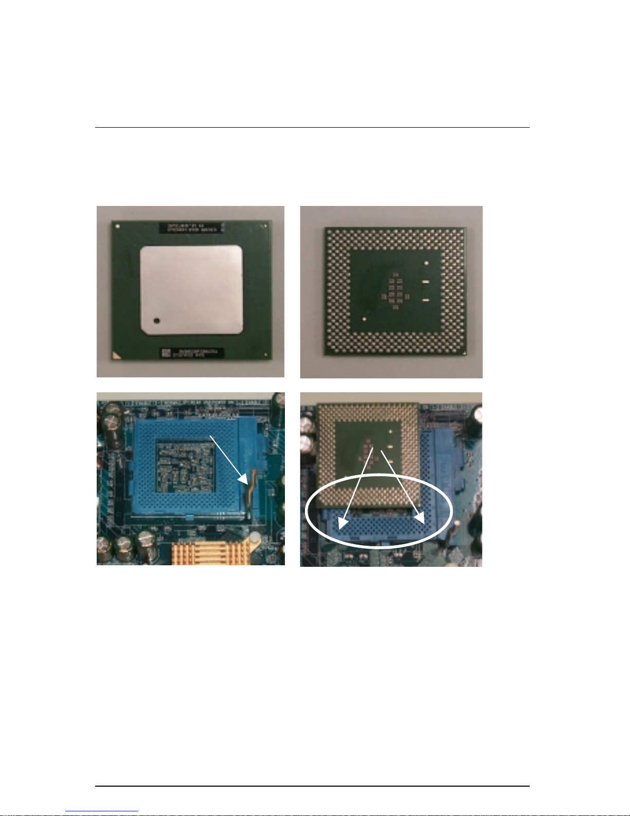
CPU Installation
Please make sure the CPU type and speed is supported by your motherboard.
For example: The newest Pentium III processor (FC-PGA2 package).
CPU Top View
CPU Bottom View
1.Pull the lever out and lift it up.
2.The notched corner should point toward the
end of the lever. The CPU will only fit in the
orientation as shown.
Socket Actuation Lever
Blank
Page 17
Page Index for CPU Speed Setup
10
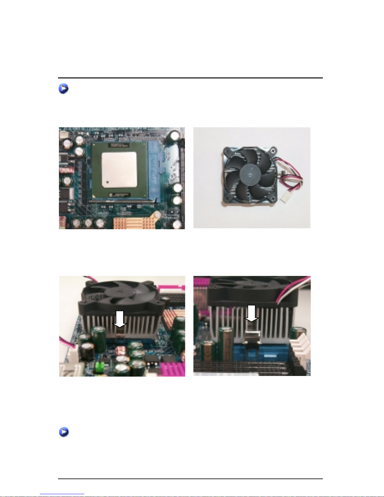
CPU Heat Sink Installation:
Beware: Please check that the heat sink is in good contact with the CPU before you turn on your
system.
Poor contact will cause over heat with might cause damage to your
processor!
3.Align CPU and insert it
(Please refer to your heatsink installation
manual for application of thermal grease to
provide better heat conduction between your
CPU and heatsink.)
4.Use compliant fan approved by Intel.
5.Hook one end of the cooler bracket to the CPU socket.
6. Hook the other end of the cooler bracket to the CPU socket.
7. Make sure the CPU fan is plugged to the CPU fan connector, than install complete.
(Please refer to the cooler’s installation manual for detailed installation steps)
Page 18
6OXET Series Motherboard
11
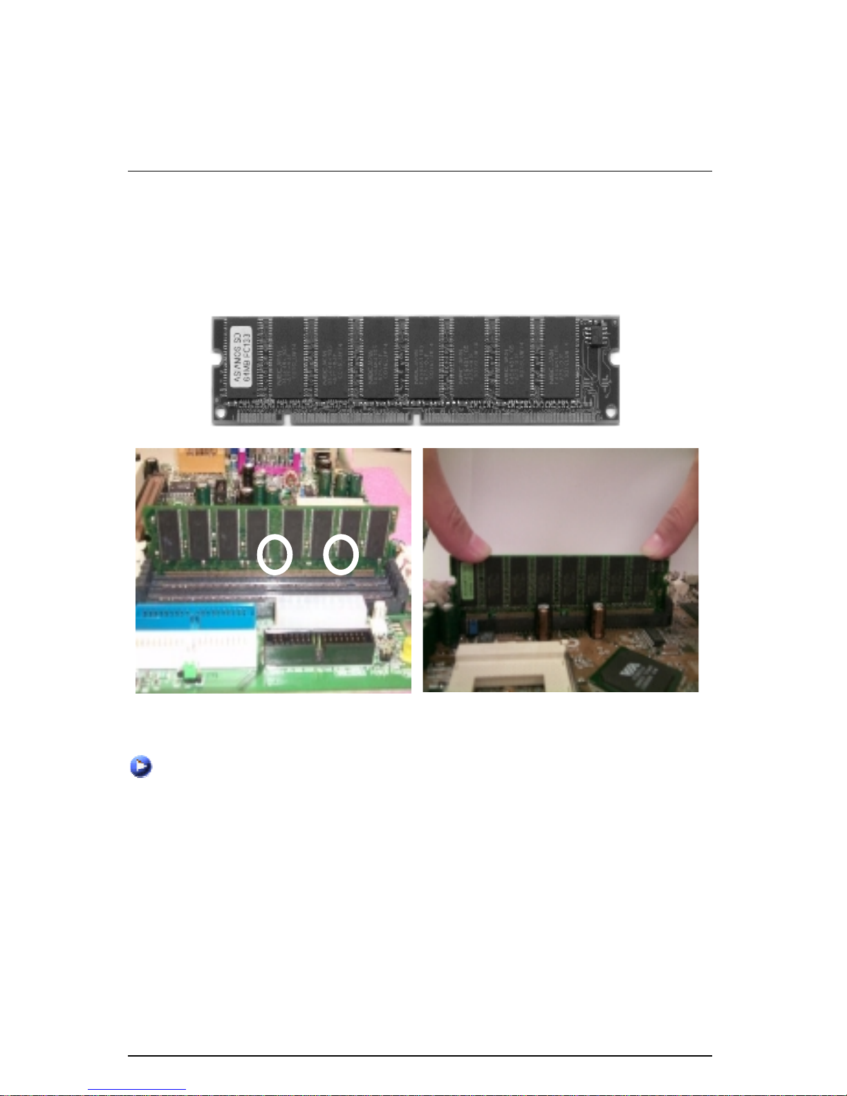
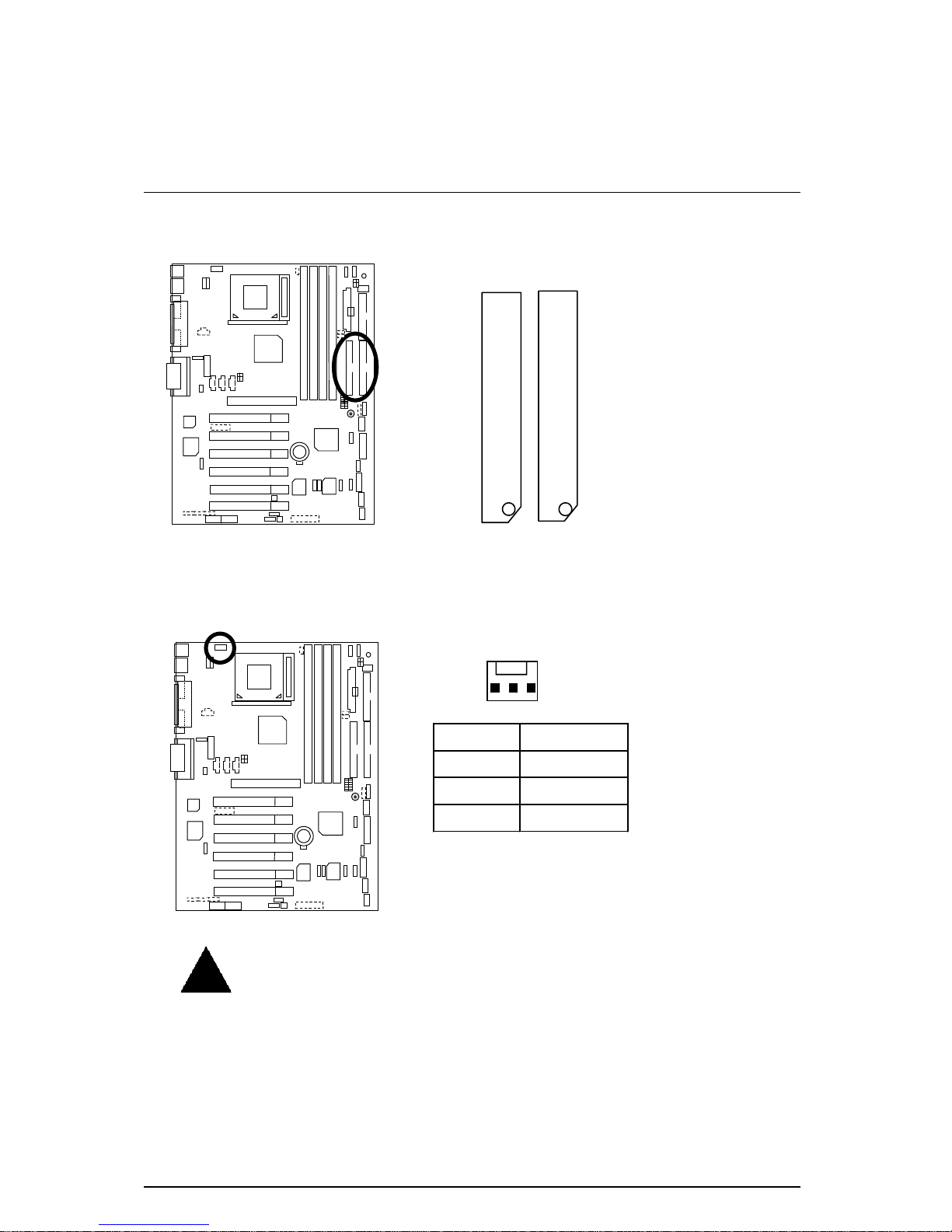
Memory Installation
The motherboard has 4 dual inline memory modul e (DIMM) soc kets support 4 banks. The BIOS
will automatically detects memory type and size. To install the memory module, just push it
vertically into the DIMM Slot .The DIMM module can only fit in one direction due to the two notch.
Memory size can vary between sockets.
SDRAM
1. The DIMM slot has two notch, so the DIMM
memory module can only fit in one direction.
2. Insert the DIMM memory module verticall y
into the DIMM slot. Then push it down.
3. Close the plastic clip at both edges of the DIMM slots to lock the DIMM module.
Reverse the installation steps when you wish to remove the DIMM module.
Page 19

Page Index for CPU Speed Setup
12
Page Index for CPU Speed Setup/Connectors/Panel and Jumper Definition
Page
CPU Speed Setup P.8
Connectors P.14
ATX Power P.14
COM A / COM B / LPT Port P.14
CN9 (Front USB Port) P.15
CN13 (Front Audio)[Optional] P.15
Floppy Port P.16
Game & Audio Port P.16
IDE 1(Primary)/ IDE 2(Secondary) Port P.17
J1 (CPU Fan) P.17
J2 (Power Fan) P.18
J5 (CD Audio Line In) P.18
J6 (AUX_IN)[Optional] P.19
J7 (TEL)[Optional] P.19
J10 (Extra SMBUS) P.20
J12 (Wake on LAN) P.20
J13 (Ring Power On) P.21
J14 (System Fan) P.21
J15 (IA Port) [Optional] P.22
JP7 (STR LED Connector) [Optional] & LED 1 (DIMM LED)[Optional] P.22
JP9 (SPDIF)[Optional] P.23
JP13 (IR/CIR) P.23
JP27 (SCR)[Optional] P.24
JP28 (For 6 Channels Audio Card Connector) [Optional] P.24
PS/2 Keyboard & PS/2 Mouse Connector P.25
USB Connector P.25
JP34 (Serial IRQ) P.26
AGP_OV (AGP Over Voltage) [Optional] P.26
RAM_OV (RAM Over Voltage) [Optional] P.27
Panel and Jumper Definition P.28
J11 (2x11 Pins Jumper) P.28
JP1 (Rear USB Device Wake up Selection) P.29
JP3 (PS/2 Keyboard Power On) P.29
JP4 (STR Enable) [Optional] P.30
JP12 (Internal Buzzer Connector) [Optional] P.30
JP14 (Timeout Reboot Function) P.31
JP15 (Safe mode / Recovery / Normal P.31
Page 20

6OXET Series Motherboard
13
JP18 (Clear CMOS Function) P.32
JP19 (Front USB Device Wake up Selection) P.32
JP20 (FWH Flash Write Protection) [Optional] P.33
JP21 (Top Block Lock) P.33
JP22 (Case Open) P.34
JP23 (PCI/AGP 3VAUX) P.34
JP24 & JP31 (CNR Selection) [Optional] P.35
JP26 (Onboard Sound Function Selection) [Optional] P.35
JP32 (SPDIF Function Selection) [Optional] P.36
JP33 (Front MIC Selection) [Optional] P.36
BAT1 (Battery) P.37
Page 21
Connectors
14
Connectors
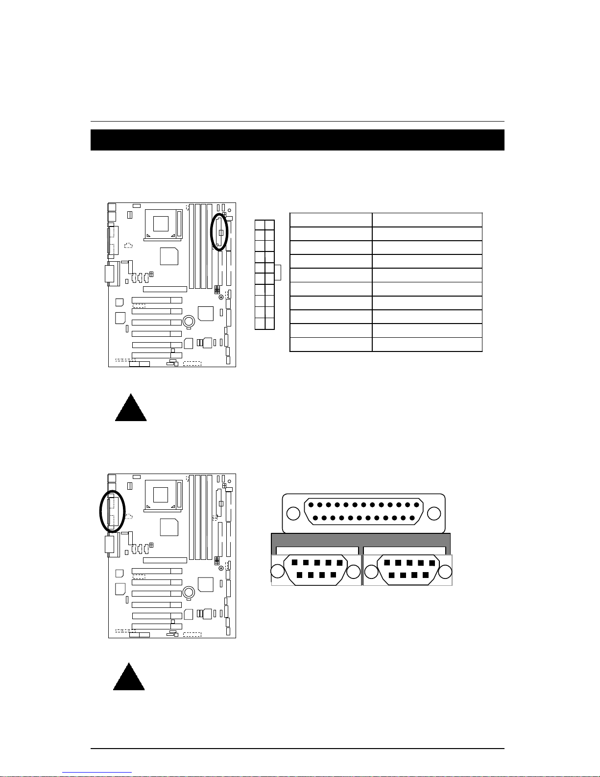
ATX Power
Pin No. Definition
3,5,7,13,15-17 GND
1,2,11 3.3V
4,6,19,20 VCC
10 +12V
12 -12V
18 -5V
8 Power Good
9 5V SB stand by+5V
14 PS-ON(Soft On/Off)
11
10
1
20
Please note:
A
C power cord should only be connected to your power supply unit after ATX power
cable and other related devices are firmly connected to the mainboard.
COM A / COM B / LPT Port
COM A
LPT Port
COM B
Please note:
This mainboard supports 2 standard COM ports and 1 LPT port. Device like
printer can be connected to LPT port, mouse and modem etc can be
connected to COM ports.
Page 22
6OXET Series Motherboard
15
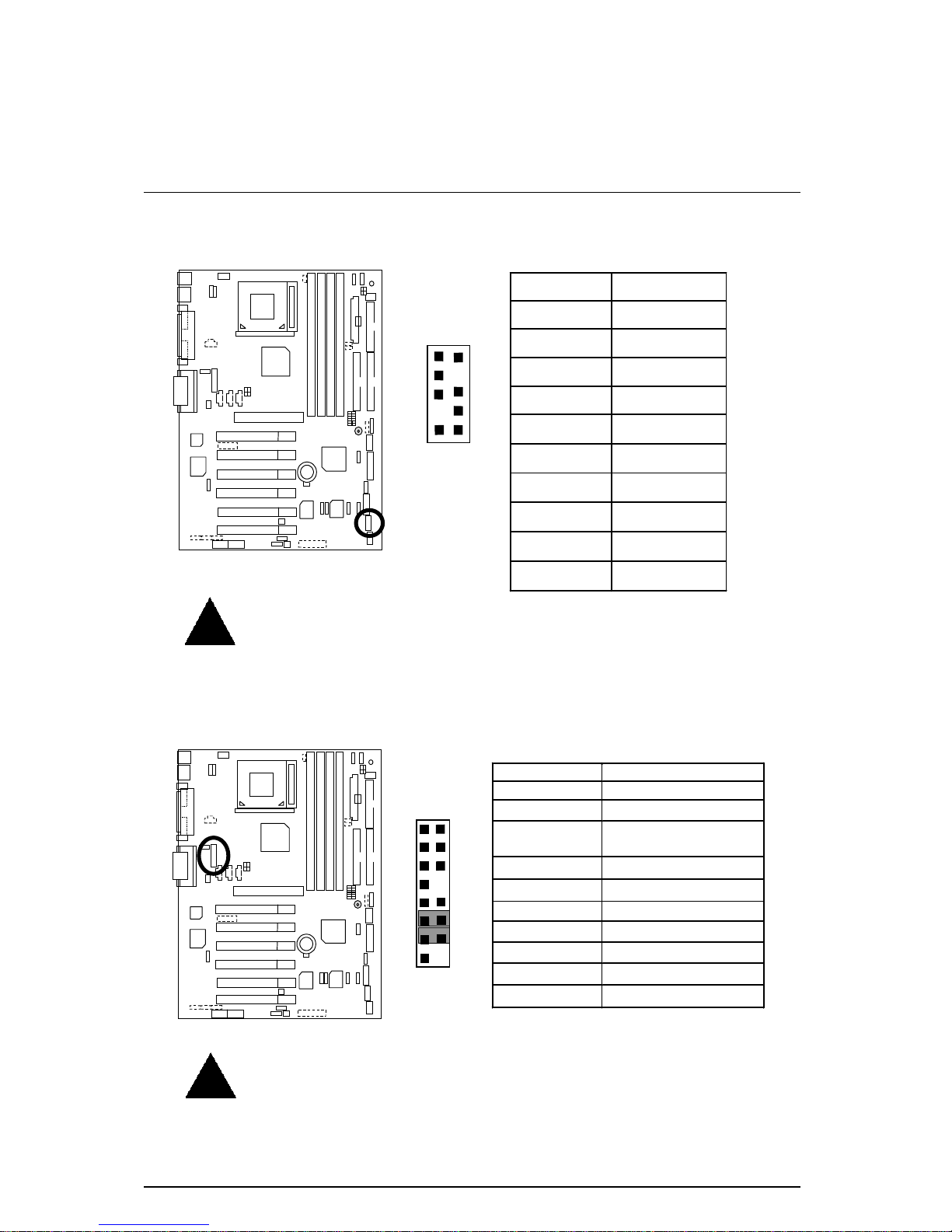
CN9: Front USB Port
Pin No. De fin itio n
1 Power
2 GND
3 USB D24 NC
5 USB D2+
6 USB D3+
7 NC
8 USB D39 GND
10 Power
9
1
10
2
Please note:
Be careful with the polarity of the front panel USB connector. Check the pin
assignment while you connect the front panel USB cable. Please contact your
nearest dealer for optional front panel USB cable.
CN13 :Front Audio (Optional)
15
1
16
2
Pin No. De fin ition
1 Incase speaker (R)
2 Incase speaker (L)
3,4,5,6,
10,15
GND
7 +12V
8,16 NC
9 MIC
11 Front Audio (R)
13 Front Audio (L)
12 Rear Audio (R)
14 Rear Audio (L)
Please note
: If you want to use “Front Audio” connector, you must move
11-12,13-14 Jumper.
In order to utilize the front audio header, your chassis must have front audio
connector. Also please make sure the pin assigment on the cable i s the same as
the pin assigment on the MB header. To find out if the chassis you are buying
support front audio connector, please contact your dealer.
Page 23
Connectors
16
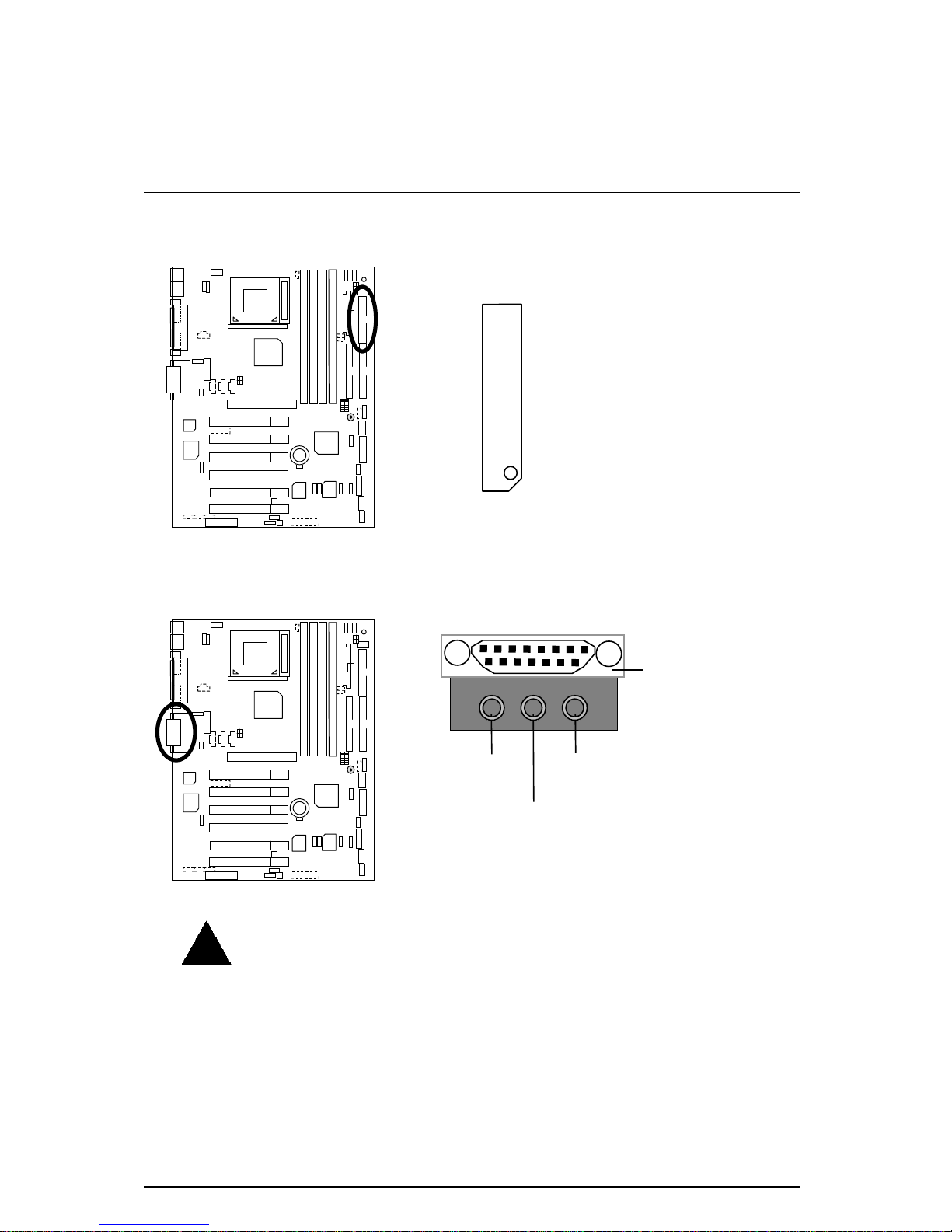
Floppy Port
Red Line
Game & Audio Port
MIC In
Game
Port
Line In/Line Out2 (Optional)
Line Out 1
Please note:
Line Out 1: Line Out or SPDIF (The SPDIF output is capable of providing
digital audio to external speakers or compressed AC3 data to an external Dolby digital
decoder). To enable SPDIF, simply insert SPDIF connector into Line Out1. Line Out1
will become SPDIF Out automatically. (see page 55 for more information).
To enable Four Speaker (for Creative 5880 audio only), simply follow instructions on
page 53 and Line In will become Line Out2 to support second pair of stereo speakers.
Page 24
6OXET Series Motherboard
17
IDE1 (Primary), IDE2 (Secondary) Port
IDE 2 IDE 1
Red Line
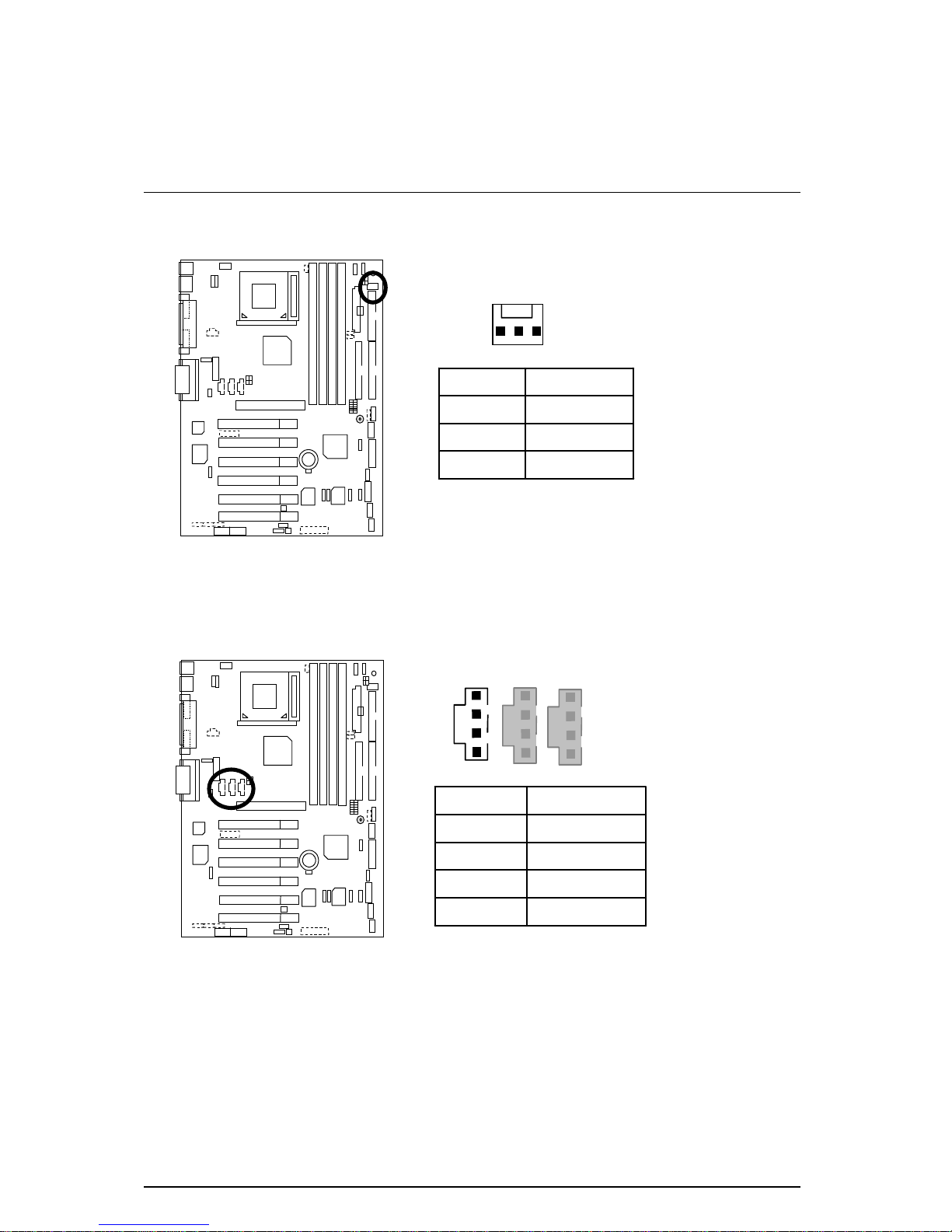
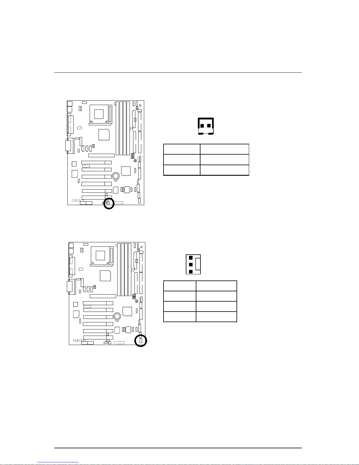
J1: CPU Fan
Pin No. Definition
1 GND
2 +12V
3 SENSE
1
Please note:
A proper installation of the CPU cooler is essential to prevent the CPU
from running under abnormal condition or damaged by overheating.
Page 25
Connectors
18
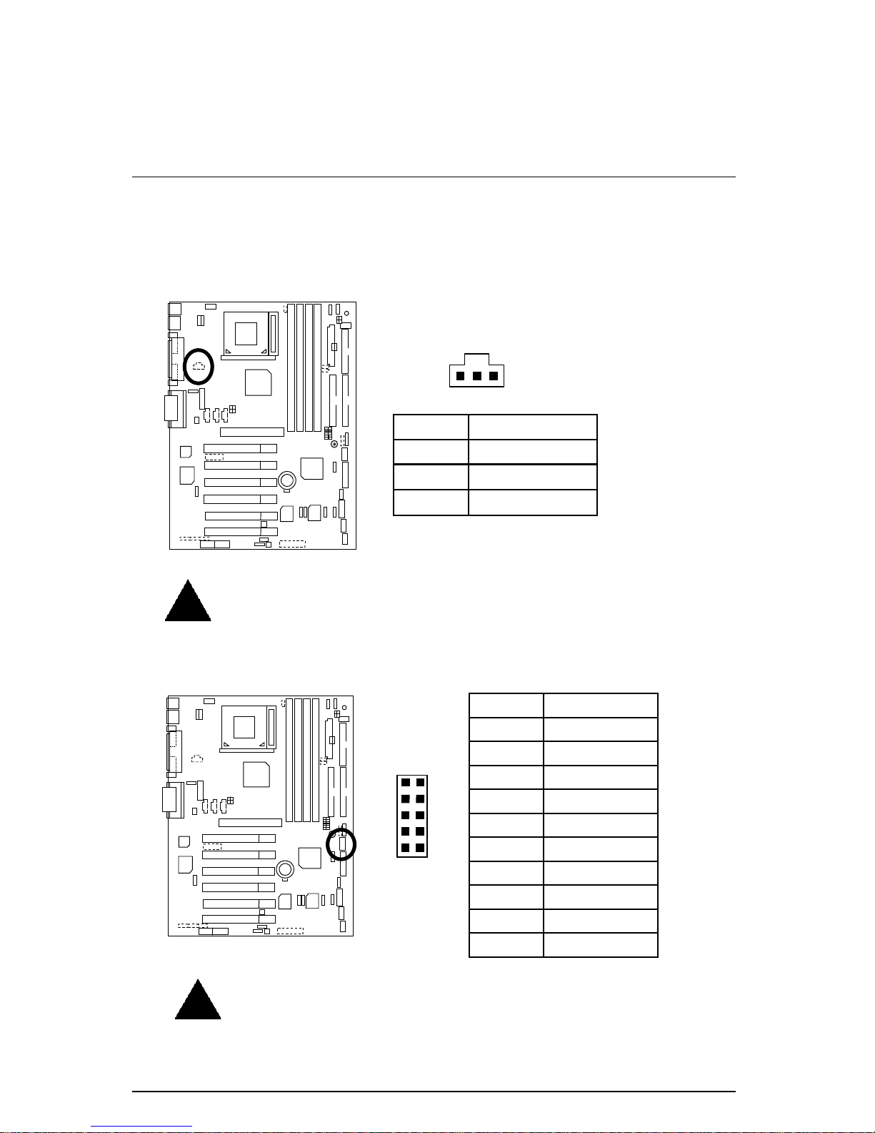
J2: Power Fan
Pin No. Definition
1 GND
2 +12V
3 SENSE
1
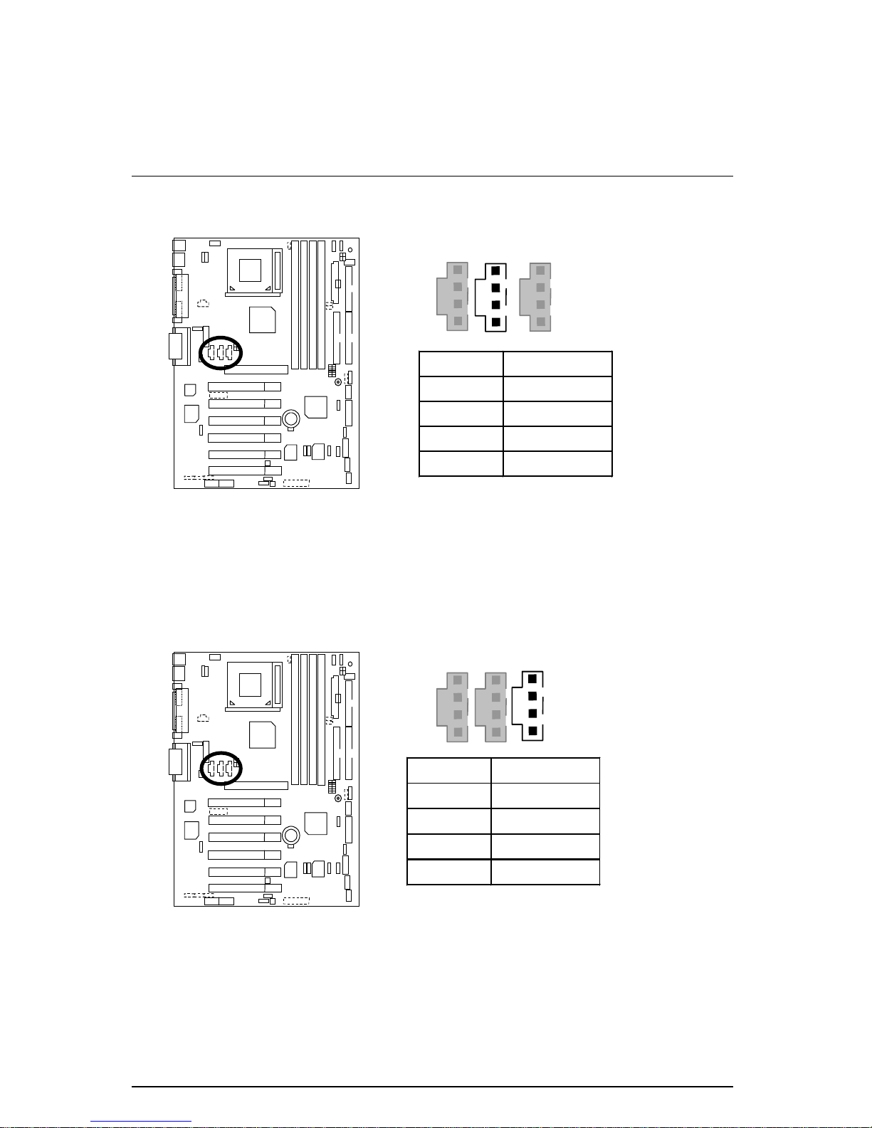
J5: CD Audio Line In
Pin No. Definitio n
1 CD-L
2 GND
3 GND
4 CD-R
1
Page 26
6OXET Series Motherboard
19
J6: AUX_IN (Optional)
Pin No. Definition
1 AUX-L
2 GND
3 GND
4 AUX-R
1
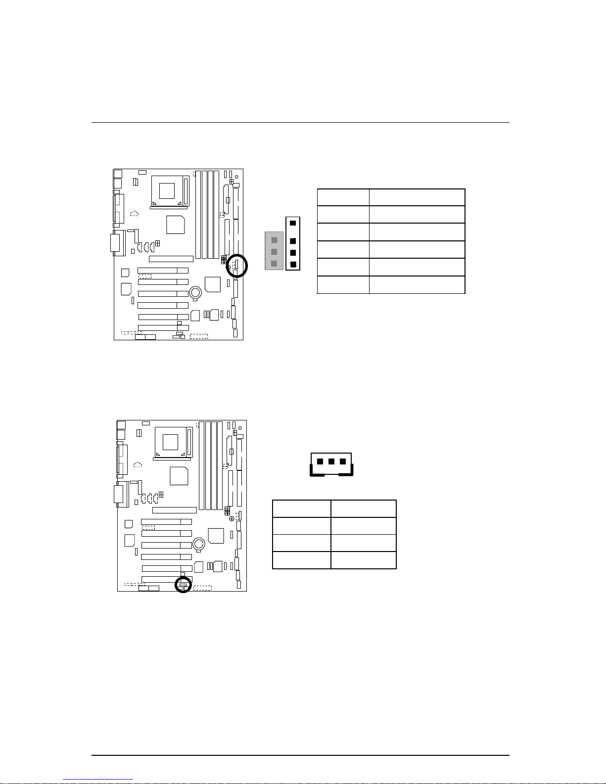
J7: TEL: The connector is for Modem with internal voice connector
(Optional)
Pin No. De fin itio n
1 Signal-In
2 GND
3 GND
4 Signal-Out
1
Page 27
Connectors
20
J10: Extra SMBUS
1
Pin No. Definition
1 SMB CLK
2 NC
3 GND
4 SMB DATA
5 +5V
J12: Wake On LAN
Pin No. Definition
1 +5V SB
2 GND
3 Signal
1
Page 28
6OXET Series Motherboard
21
J13: Ring Power On (Internal Modem Card Wake Up)
Pin No. Defin itio n
1 Signal
2 GND
1
J14: System Fan
Pin No. Definition
1 GND
2 +12V
3 SENSE
1
Page 29
Connectors
22
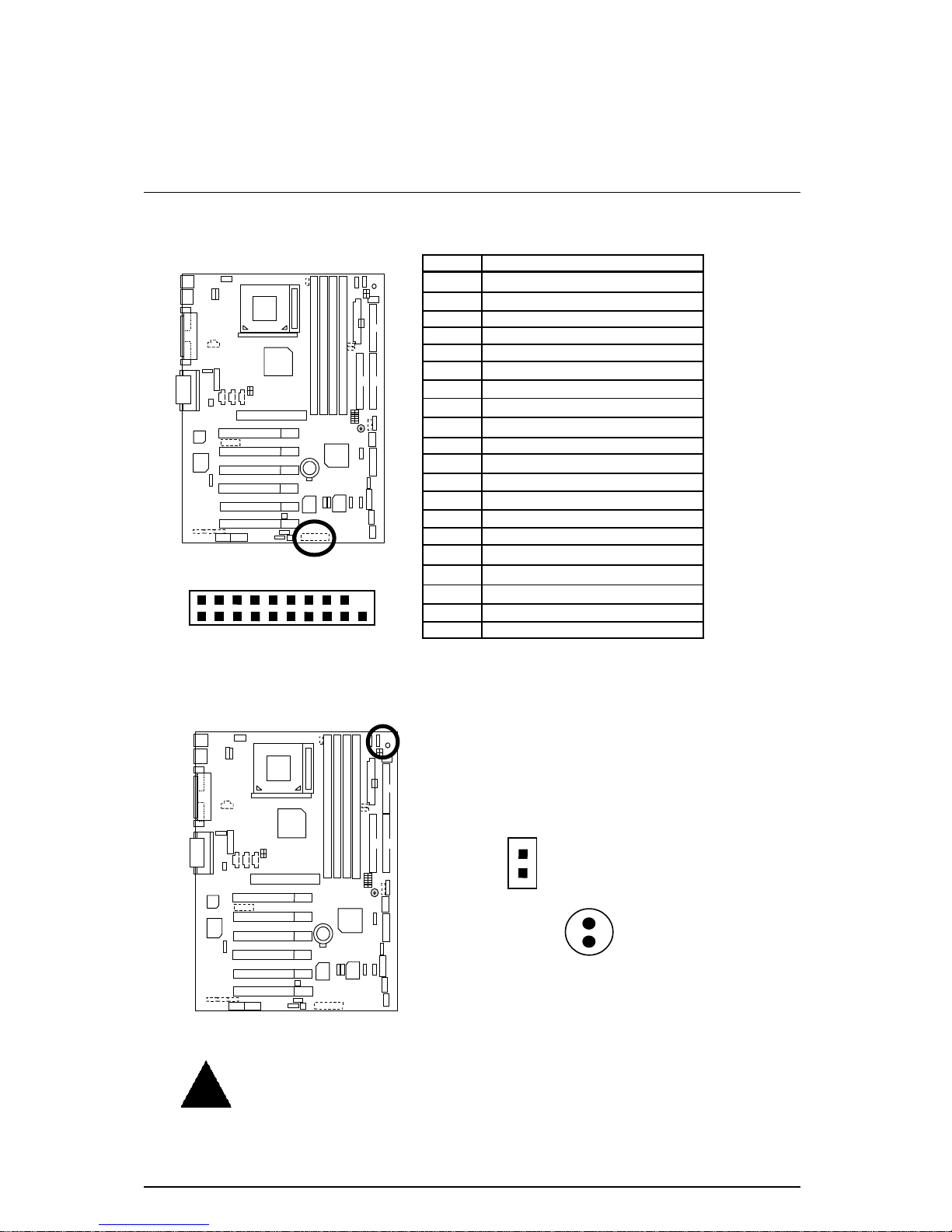
J15: IA Port (Optional)
Pin No. Definition
1 Giga-byte web-site
2 Internet
3 Finance
4 Entertainment
5 Shopping
6 Searching
7 People
8 E-mail
9 Play-pause
10 Forward
11 Rewind
12 Eject
13 Stop
14 Mute
15 Mic Volume up
16 Mic Volume down
17 Speaker Volume up
18 Speaker Volume down
19 Ground
20 NC
19
1
20
2
JP7: STR LED Connector (Optional)& LED1: DIMM LED (Optional)
STR LED Connector External
+
DIMM LED
(Optional)
1
Please note:
Do not remove memory modules while DIMM LED is on. It might cause short
or other unexpected damages due to the 3.3V stand by voltage. Remove
memory modules only when STR function is disabled by jumper and AC
Power cord is disconnected.
Page 30
6OXET Series Motherboard
23
JP9: SPDIF(The SPDIF output is capable of providing digital audio to
external speakers or compressed AC3 data to an external Dolby digital
decoder.)[Optional]
Pin No. Definition
1 VCC
2 SPDIF OUT
3 GND
1
Please note:
The SPDIF output is capable of providing digital audio to external speakers or
compressed AC3 data to an external Dolby Digital Decoder. Use this feature only
when your stereo system has digital output function.
JP13: IR/CIR
Pin No. Definition
1 VCC
2 NC
3 IRRX
4 GND
5 IRTX
6 NC
7 CIRRX
8 VCC
9 CIRTX
10 NC
1
5 6 10
Please note:
Please make sure the pin 1 on the IR device is aling with pin 1 the connector.
To enable the IR/CIR function on the board, you are required to purchase an
option IR/CIR module. For detail information please contact your autherized
Giga-Byte distributor.
Page 31

Connectors
24
JP27: SCR: Smart Card Reader (Optional)
Pin No. De finitio n
1 VCC
2 NC
3 NC
4 NC
5 SCRFET
6 SCRRST
7 SCRCLK
8 NC
9 NC
10 SCRIO
11 GND
12 SCRPRES
13 NC
14 NC
13
1
14
2
This MB supports smart card reader. To enable smart card reader function an
optional smart card reader box is required. Please contact your autherized
distributor.
JP28: For 6 Channels Audio Card Connector (Optional)
13
1
14
2
Pin No. Definition
1 +5V
2 Signal
3 GND
4 Signal
5 +3.3V
6 Signal
7 GND
8 +12V
9 Signal
10 NC
11 Signal
12 Signal
13 Signal
14 GND
Page 32

6OXET Series Motherboard
25
PS/2 Keyboard & PS/2 Mouse Connector
PS/2 Mouse/ Keyboard
Pin No. Definition
1 Data
2 NC
3 GND
4 Power
5 Clock
6 NC
PS/2 Keyboard
PS/2 Mouse
1
2
3
4
5
6
Please note:
This mainboard supports standard PS/2 keyboard and PS/2 mouse interface
connector.
USB Connector
Pin No. Definition
1 USB V0
2 USB D03 USB D0+
4 GND
5 USB V1
6 USB D17 USB D1+
8 GND
1
2
3
4
8
7
6
5
Please note:
Before you connect your device(s) into USB connector(s), please make sure your
device(s) has a standard USB interface like, USB keyboard, mouse, scanner , zip,
buzzer… Also make sure your OS supports USB controller (Win 95 w/ USB
supperment, Win98, Windows 2000, Windows ME, Win NT w/ SP 6). If your OS
does not support USB controller, please contact OS vander for passible patch or
driver upgrade. For more information please contact your OS or device(s) vanders.
Page 33

Connectors
26
JP34: Serial IRQ
Pin No. Defin itio n
1 Signal
2 GND
1
AGP_OV: AGP Over Voltage (Optional)
SW1 SW2
1.5V OFF OFF
(Default)
1.6V ON OFF
1.7V OFF ON
ON
2 1
Page 34

6OXET Series Motherboard
27
RAM_OV: RAM Overvoltage (Optional)
SW1 SW2
3.3V OFF OFF
(Default)
3.4V ON OFF
3.5V OFF ON
ON
1
2
Page 35

Panel and Jumper Defi ni t i on
28
Panel And Jumper Definition
J11: For 2x11 Pins Jumper
RE
GN GD
PW
P+ P
−
P
−
S P K
HD
1
1
1
1
1
GN (Green Switch) Open: Normal Operation
Close: Entering Green Mode
GD (Green LED) Pin 1: LED anode(+)
Pin 2: LED cathode(−)
HD (IDE Hard Disk Active LED) Pin 1: LED anode(+)
Pin 2: LED cathode(−)
SPK (Speaker Connector) Pin 1: VCC(+)
Pin 2- Pin 3: NC
Pin 4: Data(−)
RE (Reset Switch) Open: Normal Operation
Close: Reset Hardware System
P+P−P−(Power LED)
Pin 1: LED anode(+)
Pin 2: LED cathode(−)
Pin 3: LED cathode(−)
PW (Soft Power Connector) Open: Normal Operation
Close: Power On/Off
Please note:
Please connect the power LED, PC speaker, reset switch and power switch etc of
your chass is front panel t o the front panel jumper according to the pin assignment above.
Page 36

6OXET Series Motherboard
29
JP1: Rear USB Device Wake up Selection (USB Connector Æ USB)
Pin No. Definition
1-2 close
Enable Rear USB Device
Wake up
2-3 close Normal (Default)
USB
Please note:
To use “USB KB/MS Wakeup from S3” function, set BIOS setting
“USB KB/MS Wake up from S3” to ENABLED and enable jumpers JP1& JP4. To
prevent user confusion, it is recommended to enable jumper JP19 (Front US
B
Device wake-up function).
*(Power on the computer and as soon as memory counting st arts, press <Del>.
You will enter BIOS Setup. Select the item “POWER MANAGEMENT SETUP”,
then select “USB KB/MS Wake up from S3”. Remember to save the setting b
y
pressing "ESC" and choose the “SAVE & EXIT SETUP” option.)
1
Normal
(Default)
1
Enable
JP3: PS/2 Keyboard Power On
Pin No. Definition
1-2 close PS/2 Keyboard Power on
Enable
2-3 close Normal (Default)
Please note
:PS/2 keyboard power on will enable user to power on his compute
r
by pressing the designated key/keys on the PS/2 keyboard. To enable PS/2
keyboard power on, set jumper JP3 to 1-2, and then enable t he PS/2 keyboard
power on function to assign the key/keys of your choice inside th e BIOS setup
Menu.
Normal
(Default)
1 1
Enable
Page 37

Panel and Jumper Defi ni tion
30
JP4: STR Enable (Optional)
Pin No. Definition
1-2 close STR Enable
2-3 close STR Disable (Default)
1
Disable
(Default)
1
Enable
JP12: Internal Buzzer Connector (Optional)
Pin No. Definition
1-2 close Internal Buzzer Enable
(Default)
2-3 close Internal Buzzer Disable
1
1
Enable
(Default)
Disable
Page 38

6OXET Series Motherboard
31
JP14: Timeout Reboot Function
Pin No. Definition
1-2 close No Reboot on Timeout
(Default)
2-3 close Timeout Reboot
1
Please note:
This MB supports time out reboot function. If user’s system lock up, the reboot
timer will start to count. Once the timer count to specific value the system will
reboot automaticly. When this event happened the system will boot up in safe
BIOS mode.
1
No Reboot on
Timeout
(Default)
Timeout
Reboot
JP15: Safe mode/Recovery/Normal
Pin No. Definition
1-2close Normal (Default)
2-3close Safe mode
1-2-3open Recovery
Please note:
Sometime the system can not star t up due to the setti ng in the
CMOS/BIOS, to restore the CMOS/BIOS setting back to its safe setti ng the
jumper can be set to 2-3. Once your system can start up you can set the
jumper back to its normal position 1-2.
1 1
Normal
(Default)
Safe mode
Recove r y
1
Page 39

Panel and Jumper Defi ni tion
32
JP18: Clear CMOS Function
Pin No. Definition
1-2 close Clear CMOS
2-3 close Normal (Default)
Please note:
You may clear the CMOS data to it’s default values by this jumper.
1
1
Normal
(Default)
Clear
CMOS
JP19:Front USB Device Wake up Selection (USB Port Æ CN9)
Pin No. Definition
1-2 close
Enable Front USB Device
Wake up
2-3 close Normal (Default)
CN9
1 1
Normal
(Default)
Enable
Please note
, To use “USB KB/MS Wakeup from S3” function, set BIOS setting
“USB KB/MS Wake up from S3” to ENABLED and enable jumpers JP19& JP4. To
prevent user confusion, it is recommended to enable jumper JP1 (Rear USB
Device wake-up function).
*(Power on the computer and as soon as memory counting sta rts, press <Del>.
You will enter BIOS Setup. Select the item “POWER MANAGEMENT SETUP”,
then select “USB KB/MS Wake up from S3”. Remember to save the setting b
y
pressing "ESC" and choose the “SAVE & EXIT SETUP” option.)
Page 40

6OXET Series Motherboard
33
JP20: FWH Flash Write Protection (Optional)
Pin No. Definition
1-2 close Write Protection
2-3 close Normal (Default)
Please note
, To flash/upgrade BIOS on this MB JP20 must be set to 2-3 close.
We recommend JP20 to be set to “1-2 close”, whenever user does not need to
flash/upgrade the BIOS.
1
1
Normal
(Default)
Write
Protection
JP21: Top Block Lock
Pin No. Definition
1-2 close Top Block Unlock (Default)
2-3 close Top Block Lock
Please note:
To upgrade BIOS on this M/B,JP21 must be set to 1-2 close.
1 1
Unlock
(Default)
Lock
Page 41

Panel and Jumper Defi ni tion
34
JP22: Case Open (Optional)
Pin No. Definition
1 Signal
2 GND
1
JP23: PCI/AGP 3VAUX
Pin No. Definition
1-2 close Enable PCI/AGP 3.3Vsb
(Default)
2-3 close Disable PCI/AGP 3.3Vsb
1
1
Enable
(Default)
Disable
Page 42

6OXET Series Motherboard
35
JP24 & JP31: CNR Selection (Optional)
Pin No. Definition
1-2 close CNR Secondary (Default)
2-3 close
CNR Primary
AC’97 Disable
(Disable Onboard CODEC)
1
1
JP24
JP31
JP26: Onboard Sound Function Selection (Optional)
Pin No. Definition
1-2 close
Enable Onboard Sound
(Default)
2-3 close Disable Onboard Sound
1
1
Enable
(Default)
Disable
Page 43

Panel and Jumper Defi ni tion
36
JP32: SPDIF Function Selection (Optional)
Pin No. Definition
1-2 close Enable (Default)
2-3 close Disable
1 1
Enable
(Default)
Disable
JP33: Front MIC Selection (Optional)
Pin No. Defin itio n
Close Front MIC Disable
(Defa u lt)
Open Front MIC Enable
1 1
Close
(Default)
Open
Page 44

6OXET Series Motherboard
37
BAT1: Battery
+
CAUTION
Danger of explosion if battery
is incorrectly replaced.
Replace on ly with the same or
equivalent type recommended
by the manu facturer.
Dispose of u sed batteries
according to the manufacturer’s
instructions.
Page 45

Performance List
38
Performance List
The following performance data list is the testing results of some popular benchmark testing
programs.
These data are just referred by users, and there is no responsibility for dif ferent testing data values
gotten by users. (The different Hardware & Softwar e configuration will result in different benchmark
testing results.)
• CPU
Intel New PentiumIII 1.13GHz Processor
Intel Celeron 800MHz Processor
• DRAM
(128 x 1) MB SDRAM (Winbond 007WE W986408CH-75)
• CACHE SIZE
256 KB included in CPU
128 KB included in CPU
• DISPLAY
GV-GF2010D AGP Card
• STORAGE
Onboard IDE (Quantum AS30000AT 30GB)
• O.S.
Windows 2000 + SP1
• DRIVER
Display Driver at 1024 x 768 x 16bits colors x 75Hz
IUCD ver. 1.72 for Intel chipset M.B.
Processor
Intel New Pentium III
1.13GHz
Socket 370
(133 x 8.5)
Intel Celeron
800MHz
Socket 370
(100 x 8)
Winbench99 (ver. 1.2g)
Business Disk 7390 7060
Hi-End Disk 15400 13600
Business Graphics 472 263
Hi-End Graphics 1020 637
Winstone2001
Content Creation 39.6 31.9
Business 41 29.5
0
If you wish to maximize the performance of your system, please refer to the detail on P.73
Page 46

6OXET Series Motherboard
39
Block Diagram
PS/2
Socket 370
ICH2X
FW82801BA
Host Bus 66/100/133MHz
Hub
Interface
FWH
PCI Bus 33MHz
6 PCI
ATA66/100
IDE Channels
4 USB Ports
ICS
94301AF
66/100/133 MHz
66/100/133 MHz
14.318/33/48/66 MHz
100/133 MHz
IT8712F
COM Ports
LPT Port
IR/CIR
Floppy
Game Port
3.3V SDRAM
AGP 2X/4X
CNR
SMART Card
Reader
Intel
FW82815EP
-B-Ste
p
AC97
CT5880
AC-Link
Page 47

Suspend to RAM Inst al l ation
40
Suspend To RAM Installation (Optional)
A.1 Introduce STR function:
Suspend-to-RAM (STR) is a Windows 98/ME/2000 ACPI sleep mode function. When recovering
from STR (S3) sleep mode, the system is able, in just a few seconds, to retrieve the last “state” of
the system before it went to sleep and recover to that state. The “state” is stored in memory
(RAM) before the system goes to sleep. Dur ing STR sleep mode, your system uses only enough
energy to maintain critical information and system functions, primarily the system state and the
ability to recognize various “wake up” triggers or signals, respectively.
A.2 STR function Installation
Please use the following steps to complete the STR function installation.
Step-By-Step Setup
Step 1:
To utilize the STR function, the system must be in Windows 98/ME/2000 ACPI mode.
Putting Windows 98/ME/2000 into ACPI mode is fairly easy.
Setup with Windows 98/ME/2000 CD:
A. Insert the Windows 98/ME/2000 CD into your CD-ROM drive, select Start, and then Run.
B. Type (without quotes)
“D:\setup ”
in the window provided. Hit the enter key or click OK.
C. After setup completes, remove the CD, and reboot your system
(This manual assumes that your CD-ROM device drive letter is D:).
Page 48

6OXET Series Motherboard
41
Step 2:
(If you want to use STR Function, please set jumper JP4 Pin 1-2 Closed.)
Pin No. Definition
1-2 close STR Enable
2-3 close STR Disable (Default)
1
Disable
(Default)
1
Enable
Step 3:
Power on the computer and as soon as memory counting starts, press <Del>. You will enter
BIOS Setup. Select the item
“POWER MANAGEMENT SETUP”,
then select
“
ACPI Suspend
Type
: S3 (Suspend to RAM)”
. Remember to save the settings by pressing "ESC" and choose
the
“SAVE & EXIT SETUP”
option.
Congratulation! You have completed the installation and now can use the STR function.
Page 49

Suspend to RAM Inst al l ation
42
A.3 How to put your system into STR mode? (For example : Windows ME)
There are two ways to accomplish this:
1. Choose the “Stand by” item in the “Shut Down Windows” area.
A. Press the “Start” button and then select “Shut Down”
B. Choose the “Stand by” item and press “OK”
Page 50

6OXET Series Motherboard
43
2. Define the system ”power on” button to initiate STR sleep mode:
A. Double click “My Computer” and then “Control Panel”
B. Double click the “ Power Management” item.
Page 51

Suspend to RAM Inst al l ation
44
C. Select the “Advanced” tab and “Standby” mode in Power Buttons.
D. Restart your computer to complete setup.
Now when you want to enter STR sleep mode, just momentarily press the “Power on”
button.
A.4 How to recover from the STR sleep mode?
There are seven ways to “wake up” the system:
1. Press the “Power On” button.
2. Use the “PS/2 Mouse Power On” function.
3. Use the “Resume by Alarm” function.
4. Use the “Modem Ring On” function.
5. Use the “Wake On LAN” function.
6. Use the “USB Device Wake up” function.
7. Use the “PS/2 Keyboard Power On” function.
Page 52

6OXET Series Motherboard
45
A.5 Notices:
1. In order for STR to function properly, several hardware and software requirements must be
satisfied:
A. Your ATX power supply must comply with the ATX 2.01 specification (provide more than
720 mA 5V Stand-By current).
B. Your SDRAM must be PC-100 compliant.
2. Jumper JP7 is provided to connect to the STR LED in your system chassis. [Your chassis may
not provide this feature.] The STR LED will be illuminated when your system is in STR sleep
mode.
STR LED Connector External
+
DIMM LED
(Optional)
1
Please note:
Do not remove memory modules while DIMM LED is on. It might cause short
or other unexpected damages due to the 3.3V stand by voltage. Remove
memory modules only when STR function is disabled by jumper and AC
Power cord is disconnected.
Page 53

Introduce Dual BIOS
46
Introduce Dual BIOS (Optional)
A. What is Dual BIOS Technology?
Dual BIOS means that there are two system BIOS (ROM) on the motherboard, one is the
Main BIOS and the other is Backup BIOS. Under the normal circumstances, the system
works on the Main BIOS. If the Main BIOS is corrupted or damaged, the Backup BIOS can
take over while the system is powered on. This means that your PC will still be able to run
stably as if nothing has happened in your BIOS.
B. How to use Dual BIOS?
a. Boot Screen
Award Modular BIOS v 4.51PG, An Energy Star Ally
Copyright (C) 1984-98, Award Software, Inc.
Intel XXXX AGPSet BIOS for XXXX Vx.x
Check System Health ok , Vcore =2.00V
Pentium III CPU - 600MHz
<CPU ID:0652 Patch ID:0014>
Memory Test :16384K OK
Press F1 to enter Dual BIOS Utility, ESC to quit
Press
DEL
to enter SETUP
03/29/1999-I440BX-8671-2A69KG0EC-00
Press F1 to enter Dual BIOS Utility
Page 54

6OXET Series Motherboard
47
b. Dual BIOS Utility
c. Dual BIOS Item explanation:
Wide Range Protection: Disabled(Defaul t), Enabled
Status 1:
If any failure (ex. Update ESCD failure, checksum error or reset…) occurs in the Main
BIOS , just before the Operating System is loaded and after the power is on, and that
the Wide Range Protection is set to “Enable”, the PC will boot from Backup BIOS
automatically.
Status 2:
If the ROM BIOS on peripherals cards(ex. SCSI Cards, LAN Cards,..) emits signals to
request restart of the system after the user make any alteration on it, the boot up BIOS
will not be changed to the Backup BIOS.
Dual BIOS Utility V6.60.g.01K
(C) 1999, Gigabyte Technology Co., LTD.
Wide Range Protection :Disabled
Halt On BIOS Defects :Disabled
Auto Recovery :Enabled
Boot From :Main BIOS
BIOS Recovery :Main to Backup
F3: Load Default F5:Start BIOS Recovery
F7: Save And Restart F9:Exit Without Saving
Use <Space> key to toggle setup
Page 55

Introduce Dual BIOS
48
Halt On BIOS Defects : Disabled(Default), Enabled
If the BIOS occurs a checksum erro r or the Main BIOS occurs a WIDE RANGE
PROTECTION error and Halt On BIOS Defects set to Enable, the PC w ill show messages on
the boot screen, and the system will pause and wait for the user’s instruction.
If Auto Recovery :
Disabled
, it will show <or the other key to continue.>
If Auto Recovery :
Enabled
, it will show <or the other key to Auto Recover.>
Auto Recovery : Enabled(Default), Disabled
When one of the Main BIOS or Backup BIOS occurs checksum failure, the w orking BIOS will
automatically recover the BIOS of checksum failure.
(In the Power Management Setup of the BIOS Setting, if ACPI Suspend Type is set to
Suspend to RAM, the Auto Recovery will be set to Enable automatically.)
(If you want to enter the BIOS setting, please press
“Del”
key when the boot screen
appears.)
Boot From : Main BIOS(Default), Backup BIOS
Status 1:
The user can set to boot from main BIOS or Backup BIOS.
Status 2:
If one of the main BIOS or the Backup BIOS fails, this item “Boot From : Main BIOS(Default)”
will become gray and will not be changed by user.
BIOS Recovery : Main to Backup
Auto recovery message:
BIOS Recovery: Main to Backup
The means that the Main BIOS works normally and could automatically recover the
Backup BIOS.
BIOS Recovery: Backup to Main
The means that the Backup BIOS works normally and could automatically recover the
Main BIOS.
(This auto recovery utility is set by system automatically and can’t be changed by user.)
Page 56

6OXET Series Motherboard
49
DualBIOS
TM
Technology FAQ
GIGABYTE T echnology is pleased to intr oduce DualBIOS technology, a hot spare for your system
BIOS. This newest “Value-added” feature, in a long series of innovations from GIGABYTE, is
available on GA-6OXET Series motherboard. Future GIGABYTE motherboards will also
incorporate this innovation.
What’s DualBIOSTM?
On GIGABYTE motherboards w6ith DualBIOS there are physically two BIOS chips. For simplicity
we’ll call one your “Main BIOS” and the other we’ll call your “Backup” BIOS (your “hot spare”). If
your Main BIOS fails, the Backup BIOS almost automatically takes over on your next system boot.
Almost automatically and with virtually zero down time! Whether the problem is a failure in flashing
your BIOS or a virus or a catastrophic failure of the Main BIOS chip, the result is the same - the
Backup BIOS backs you up, almost automatically.
Page 57

Introduce Dual BIOS
50
I. Q: What is DualBIOSTM technology?
Answer:
DualBIOS technology is a patented technology from Giga-Byte Technology. The concept of this
technology is based on the redundancy and fault tolerance theory. DualBIOS
TM
technology simply
means there are two system BIOSes (ROM) integrated onto the motherboard. One is a main BIOS,
and the other is a backup BIOS. The mainboard will operate normally with the main BIOS, however,
if the main BIOS is cor rupt or damaged for various reasons, the backup BIOS w ill be automatically
used when the system powered-On. Your PC will operate as before the main BIOS wa s damaged,
and is completely transparent to the user.
II. Q: Why does anyone need a motherboard with DualBIOS
TM
technology?
Answer:
In today’s systems there are more and more BIOS failures. The most common reasons are virus
attacks, BIOS upgrade failures, and/or deterioration of the BIOS (ROM) chip itself.
1. New computer viruses are being found that attack and destroy the system BIOS. They may
corrupt your BIOS code, causing your PC to be unstable or even not boot normally.
2. BIOS data will be corrupted if a power loss/surge occurs, or if a user resets the system, or if
the power button is pressed during the process of performing a system BIOS upgrade.
3. If a user mistakenly updates their mainboard with the incorrect BIOS file, then the system
may not be able to boot correctly. This may cause the PC system hang in operation or during
boot.
4. A flash ROM's life cycle is limited according to electronic characteristics. The modern PC
utilizes the Plug and Play BIOS, and is updated regularly. If a user changes peripherals often,
there is a slight chance of damage to the flash
ROM.
With Giga-Byte Technology’s patented DualBIOS
TM
technology you can reduce the possibility of
hangs during system boot up, and/or loss BIOS data due to above reasons. This new technology
will eliminate valuable system down time and costly repair bills cause by BIOS failures.
Page 58

6OXET Series Motherboard
51
III. Q: How does DualBIOSTM technology work?
Answer:
1. DualBIOSTM technology provides a wide range of protection during the boot up procedure. It
protects your BIOS during system POST, ESCD update, and even all the way to PNP
detection/assignment.
2. DualBIOS
TM
provides automatic recovery for the BIOS. When the first BIOS used during boot
up does not complete or if a BIOS checksum error occurs, boot-up is still possible. In the
DualBIOS
TM
utility, the "Auto Recovery" option will guarantee that if either the main BIOS or
backup BIOS is corrupted, the DualBIOS
TM
technology will use the good BIOS and correct the
wrong BIOS automatically.
3. DualBIOS
TM
provides manual recovery for the BIOS. DualBIOSTM technology contains a
built-in flash utility, which can flash your system BIOS from backup to main and/or visa versa.
There is no need for an OS-dependent flash utility program.
4. DualBIOS
TM
contains a one-way flash utility. The built-in one-way flash utility will ensure that
the corrupt BIOS is not mistaken as the good BIOS during recovery and that the correct BIOS
(main vs. backup) will be flashed. This will prevent the good BIOS from being flashed.
IV. Q: Who Needs DualBIOSTM technology?
Answer:
1. Every user should have DualBIOSTM technology due to the advancement of computer viruses.
Everyday, there are new BIOS-type viruses discovered that will destroy your syst em BIOS.
Most commercial products on the market do not have solutions to guard against this type of
virus intrusion. The DualBIOS
TM
technology will provide a state-of-the-art solution to protect
your PC:
Case I.) Vicious computer viruses may wipe out your entire system BIOS. With a conventional
single system BIOS PC, the PC will not be functional until it is sent for repairs.
Case II.) If the "Auto Recovery" option is enabled in the DualBIOS
TM
utility, and if a virus
corrupts your system BIOS,
the backup BIOS will automatically reboot the system and correct
the main BIOS.
Case III.) A user may over ride booting from the main system BIOS. The DualBIOS
TM
utility may
be entered to manually change the boot sequence to boot from the backup BIOS.
Page 59

Introduce Dual BIOS
52
2. During or after a BIOS upgrade, if DualBIOSTM detects that the main BIOS is corrupt, the
backup BIOS will take over the boot-up process automatically. Moreover, it will verify the main
and backup BIOS checksums when booting-up. DualBIOS
TM
technology examines the
checksum of the main and backup BIOS while the system is powered on to guarantee your
BIOS operates properly.
3. Power Users will have the advantage of having two BIOS versions on their mainboard. The
benefit is being able to select either version BIOS to suit the performance system needs.
4. Flexibility for high-end desktop PCs and workstation/servers. In the DualBIOSTM utility, the
option can be set, "Halt On When BIOS Defects," to be enabled to halt your system with a
warning message that the main BIOS has been corrupted. Most workstation/servers require
constant operation to guarantee services have not been interrupted. In this situation, the "Halt
On When BIOS Defects" message may be disabled to avoid system pauses during normal
booting. Another advantage you gain from Giga-Byte’s DualBIOS
TM
technology is the ability to
upgrade from dual 2 Mbit BIOS to dual 4 Mbit BIOS in the future if extra BIOS storage is need.
Page 60

6OXET Series Motherboard
53
Four Speaker & SPDIF Introduction (Optional)
Four Speaker Introduction
A. What is Four Speaker?
The Creative CT5880 audio chip can support 4 speaker output, if you select “Four speaker”
out, Line in will be change to another line out.
B. How to use Four Speaker?
a. Press the audio icon and then select “Configuration 3D Audio”
b. Two speaker (Default)
Page 61

Four Speaker & SPDIF Introduction
54
c. Click “Four speaker” item.
C. Four Speaker Application
The four speaker function will only support in application software that use Microsoft DirectX and
Creative EAX. For example, the game titles, software DVD player and MP3 player. Those
software support Microsoft DirectX, so they can support four speaker output.
Page 62

6OXET Series Motherboard
55
SPDIF Introduction
A.
What is SPDIF?
The SPDIF output is capable of providing digital audio to external speakers or compressed AC3
data to an external Dolby digital decoder.
B. How to use SPDIF?
a. Press your mouse right button in “My Computer” and then select the “Properties” item.
b. Click “Device Manager” item.
Page 63

Four Speaker & SPDIF Introduction
56
c. Press “Sound, video and game controllers” item and then select the “Creative Sound Blaster
PCI128” item.
d. Press “Settings” item and then select the “Output Mode” item.
Page 64

6OXET Series Motherboard
57
e. Click “Digital” item, Line Out will be change to SPDIF Out.
f. Recommend you to select “Autosense” , it will auto detect the audio jack you plug in to Line Out
is mono or stereo, and then change to SPDIF Out or Speaker out automatically.
Page 65

@BIOSTM Introduction
58
@ BIOSTM Introduction
Gigabyte announces
@BIOS™
Windows BIOS li ve updat e utility
Have you ever updated BIOS by yourself? Or
like many other people, you just know what
BIOS is, but always hesitate to update it?
Because you think updating newest BIOS is
unnecessary and actually you don’t know how
to update it.
Maybe not like others, you are very experienced in BIOS updating and spend quite a
lot of time to do it. B ut of course you don’t like to do it too much. First, download different
BIOS from website and then switch the operating system to DOS mode. Secondly, use
different flash utility to update BIOS. The above process is not a interesting job. Besides,
always be carefully to store the BIOS source code correctly in your disks as if you update
the wrong BIOS, it will be a nightmare.
Certainly, you wonder why motherboard vendors could not just do something right to
save your time and effort and save you from the lousy BIOS updating work? Here it
comes! Now Gigabyte announces @BIOS
™
--the first Windows BIOS live update utility.
This is a smart BIOS update software. It could help you to download the BIOS from
internet and update it. Not like the other BIOS update software, it’s a Windows utility.
With the help of “@BIOS
™
’, BIOS updating is no more than a click.
Besides, no matter which mainboard you are using, if it’s a Gigabyte’s product*,
@BIOS
™
help you to maintain the BIOS. This utility could detect your correct mainboard
model and help you to choose the BIOS accordingly. It then downloads the BIOS from
the nearest Gigabyte ftp site automatically. There are several different choices; you
could use “Internet Update” to download and update your BIOS directly. Or you may
want to keep a backup for your current BIOS, just choose “Save Current BIOS” to save it
first. You make a wise choice to use Gigabyte, and @BIOS
™
update your BIOS smartly.
You are now worry free from updating wrong BIOS, and capable to maintain and
manage your BIOS easily. Again, Gigabyte’s innovative product erects a milestone in
mainboard industries.
For such a wonderful software, how much it costs? Impossible! It’s free! Now, if you
buy a Gigabyte’s motherboard, you could find this amazing software in the attached
driver CD. But please remember, connected to internet at first, then you could have a
internet BIOS update from your Gigabyte @BIOS
™
.
Page 66

6OXET Series Motherboard
59
Easy Tune
III
TM
Introduction
Gigabyte announces EasyTune
III
™
Windows overdrive util ity
“Overdrive” might be one of the most
common issues in computer field. But have
many users ever tried it? The answer is
probably “no”. Because “overdrive” is thought
to be very difficult and includes a lot of technical
know-how, sometimes “overdrive” is even
considered as special skills found only in some enthusiasts.
But as to the experts in “overdrive”, what’s the truth? They may spend quite a lot
of time and money to study, try and use many different hardware and software tools
to do “overdrive”. And even with these technologies, they still learn that it’s quite a
risk because the safety and stability of an “overdrive“ system is unknown.
Now everything is different because of a Windows overdrive utility
EasyTune
III
™
--announced by Gigabyte. This utility has totally changed the gaming
rule of “overdrive”. This is the first overdrive utility suitable for both normal and power
users. Users can choose either “Easy Mode” or “Advanced Mode” to run “overdrive”
at their convenience. For users who choose “Easy Mode”, they just need to click
“Auto Optimize” to have auto and immediate CPU overclocking. This software will
then overdrive CPU speed automatically with the result being shown in the control
panel. If someone prefers to “overdrive” by oneself, there is also another choice.
Click “Advanced Mode” to enjoy “sport drive” class overclocking. In “Advanced
Mode”, one can change the system bus speed in small increments to get ultimate
system performance. And no matter which mainboard is used, if it’s a Gigabyte’s
product*, EasyTune
III
™
helps to perform the best of system.
Besides, different from other traditional over-clocking methods, EasyTune
III
™
doesn’t require users to change neither BIOS nor hardware switch/ jumper setting;
on the other hand, they can do “overdrive” at only one click. Therefore, this is a safer
way for “overdrive” as nothing is changed on software or hardware. If user runs
EasyTune
III
™
over system’s limitation, the biggest lost is only to restart the computer
again and the side effect is then well controlled. Moreover, if one well-performed
system speed been tested in EasyTune
III
™
, user can “Save” this bus speed and
“Load” it in next time. Obviously, Gigabyte EasyTune
III
™
has already turned the
“overdrive” technology toward to a newer generation.
This wonderful software is now free bundled in Gigabyte motherboard attached
driver CD. Users may make a test drive of “EasyTune
III
™
” to find out more amazing
features by themselves.
Page 67

Memory Installation
60
Memory Installation
The motherboard has 4 dual inline memory modul e (DIMM) soc kets support 6 banks. The BIOS
will automatically detects memory type and size. To install the memory module, just push it
vertically into the DIMM Slot .The DIMM module can only fit in one direction due to the two notch.
Memory size can vary between sockets.
Install memory in any combination table:
Location 168-pin SDRAM DIMM Modules Note
Single – Sided
DIMM1
(Bank 0,1)
Double – Sided
Single – Sided DIMM2
(Bank 2,3)
Double – Sided
Single – Sided DIMM4 have only single-sided DIMM3
(Bank 4,5)
Double – Sided DIMM4 must be empty
Single – Sided DIMM3 must install single-sided DIMM4
(Bank 4,5)
Double – Sided DIMM3 must be empty
Total System Memory (Max 512MB)
★Supports 16 / 32 / 64 / 128 / 256/ 512 MB SDRAM DIMM Modules.
0
Note:
1. DIMM 4 is optional.
2. When you’re using single-sided memory on DIMM4, you must use single-sided memory on
DIMM3. If you use double-sided memory on DIMM4, please do not insert any memory on DIMM3.
Page 68

6OXET Series Motherboard
61
Page Index for BIOS Setup Page
The Main Menu P.63
Standard CMOS Features P.66
Advanced BIOS Features P.70
Advanced Chipset Features P.73
Integrated Peripherals P.78
Power Management Setup P.84
PnP/ PCI Configurations P.88
PC Health Status P.90
Frequency / Voltage Control P.92
Load Fail-Safe Defaults P.94
Load Optimized Defaults P.95
Set Supervisor / User Password P.96
Save & Exit Setup P.97
EXIT Without Saving P.98
Page 69

BIOS Setup
62
BIOS Setup
BIOS Setup is an overview of the BIOS Setup Program. The program that allows users to modify
the basic system configur ation. This type of in formation is sto red in batte ry-backed C MOS RAM so
that it retains the Setup information when the power is turned off.
ENTERING SETUP
Power ON the computer and press <Del> immediately will allow you to enter Setup. If the message
disappears before you respond and you still wish to enter Setup, restart the system to try again by
turning it OFF then ON or pressing the "RESET" bottom on the system case. You may also restart
by simultaneously press <Ctrl> − <Alt>− <Del> keys.
CONTROL KEYS
<↑> Move to previous item
<↓> Move to next item
<←> Move to the item in the left hand
<→> Move to the item in the right hand
<Esc> Main Menu - Quit and not save changes into CMOS
Status Page Setup Menu and Option Page Setup Menu - Exit current page
and return to Main Menu
<+/PgUp> Increase the numeric value or make changes
<-/PgDn> Decrease the numeric value or make changes
<F1> General help, only for Status Page Setup Menu and Option Page Setup
Menu
<F2> Reserved
<F3> Reserved
<F4> Reserved
<F5> Restore the previous CMOS value from CMOS, only for Option Page Setup
Menu
<F6> Load the default CMOS value from BIOS default table, only for Option Page
Setup Menu
<F7>
Load the Optimized Defaults
<F8> Reserved
<F9> Reserved
<F10> Save all the CMOS changes, only for Main Menu
Page 70

6OXET Series Motherboard
63
GETTING HELP
Main Menu
The on-line description of the highlighted setup function is displayed at the bottom of the screen.
Status Page Setup Menu / Option Pag e Setup Menu
Press F1 to pop up a small help window that describes the appropriate keys to use and the
possible selections for the highlighted item. To exit the Help Window press <Esc>.
The Main Menu
(For example: BIOS Ver. :F2A)
Once you enter Award BIOS CMOS Setup Utility, the Main Menu (Figure 2) will appear on the
screen. The Main Menu allows you to select from nine s etup functi ons and two ex it choi ces . Use
arrow keys to select among the items and press <Enter> to accept or enter the sub-menu.
Figure 2: Main Menu
CMOS Setup Utility-Copyright( C ) 1984-2000 Award Software
Standard CMOS Features
Frequency/Voltage Control
Advanced BIOS Features Load Fail-Safe Defaults
Advanced Chipset Features Load Optimized Defaults
Integrated Peripherals Set Supervisor Password
Power Management Setup Set User Password
PnP/PCI Configurations Save & Exit Setup
PC Health Status Exit Without Saving
ESC:Quit
↑↓→ ←
: Select Item
F10:Sa ve & Exit Setu p
Time, Date, Hard Disk Type…
Page 71

BIOS Setup
64
••••
Standard CMOS Features
This setup page includes all the items in standard compatible BIOS.
••••
Advanced BIOS Features
This setup page includes all the items of Award special enhanced features.
••••
Advanced Chipset Features
This setup page includes all the items of chipset special features.
••••
Integrated Peripherals
This setup page includes all onboard peripherals.
••••
Power Management Setup
This setup page includes all the items of Green function features.
••••
PnP/PCI Configurations
This setup page includes all the configurations of PCI & PnP ISA resources.
••••
PC Health Status
This setup page is the System auto detect Temperature, voltage, fan, speed.
••••
Frequency/Voltage Control
This setup page is control CPU’s clock and frequency ratio.
••••
Load Fail-Safe Defaults
Fail-Safe Defaults indicates the va lue of the system parameters which the system would
be in safe configuration.
••••
Load Optimized Defaults
Optimized Defaults indicates the value o f the system parameters wh ich the system would
be in best performance configuration.
••••
Set Supervisor password
Change, set, or disable password. It allows you to limit access to the system and Setup,
or just to Setup.
••••
Set User password
Change, set, or disable password. It allows you to limit access to the system.
Page 72

6OXET Series Motherboard
65
••••
Save & Exit Setup
Save CMOS value settings to CMOS and exit setup.
••••
Exit Without Saving
Abandon all CMOS value changes and exit setup.
Page 73

BIOS Setup
66
Standard CMOS Features
The items in Standard CMOS Setup Menu (Figure 3) are divided into 9 categories. Each category
includes no, one or more than one setup items. Use the arrows to highlight the item and then use
the <PgUp> or <PgDn> keys to select the value you want in each item.
Figure 3: Standard CMOS Features
••••
Date
The date format is <week>, <month> <day> <year>.
Week The week, from Sun to Sat, determined by the BIOS and is display-only
Month The month, Jan. Through Dec.
Day The day, from 1 to 31 (or the maximum allowed in the month)
Year The year, from 1994 through 2079
CMOS Setup Utility-Copyright( C ) 1984-2000 Award Software
Standard CMOS Features
Date (mm:dd:yy) Mon , Feb 21 2000 Item Help
Time (hh:mm:ss) 2 : 31 : 24
Menu Level
IDE Primary Master Press Enter None
IDE Primary Slave Press Enter None
Change the
IDE Secondary Master Press Enter None
Day, month,
IDE Secondary Slave Press Enter None
Year and
century
Drive A 1.44M, 3.5 in.
Drive B None
Floppy 3 Mode Support Disabled
Video EGA / VGA
Halt On All, But Keyboard
Base Memory 640K
Extended Memory 63488K
Total Memory 64512K
↑↓→ ←
:Move Enter:Select +/-/PU/PD:Value F10:Save ESC:Exit F1:General Help
F5:Previous Values F6:Fail-Safe Defaults F7:Optimized Defaults
Page 74

6OXET Series Motherboard
67
••••
Time
The times format in <hour> <minute> <second>. The time is calculated base on the 24-hour
military-time clock. For example, 1 p.m. is 13:00:00.
••••
IDE Primary Master, Slave / Secondary Master, Slave
The category identifies the types of hard disk from drive C to F that has been installed in the
computer. There are two types: auto type, and manual ty pe. Manual type i s user-definable;
Auto type which will automatically detect HDD type.
Note that the specifications of your drive must match with the drive table. The hard disk will
not work properly if you enter improper information for this category.
If you select Use r Type, relat ed informa tion will be aske d to enter to the follow ing items. Enter
the information directly from the keyboard and pres s <Enter>. Such information should be
provided in the documentation form your hard disk vendor or the system manufacturer.
CYLS. Number of cylinders
HEADS number of heads
PRECOMP write precomp
LANDZONE Landing zone
SECTORS number of sectors
If a hard disk has not been installed select NONE and press <Enter>.
••••
Drive A / Drive B
The category identifies the types of floppy disk drive A or drive B that has been installed in the
computer.
None No floppy drive installed
360K, 5.25 in. 5.25 inch PC-type standard drive; 360K byte capacity.
1.2M, 5.25 in. 5.25 inc h AT-type high-density drive; 1.2M byte capacity (3.5 inch
when 3 Mode is Enabled).
720K, 3.5 in. 3.5 inch double-sided drive; 720K byte capacity
1.44M, 3.5 in. 3.5 inch double-sided drive; 1.44M byte capacity.
2.88M, 3.5 in. 3.5 inch double-sided drive; 2.88M byte capacity.
Page 75

BIOS Setup
68
••••
Floppy 3 Mode Support (for Japan Area)
Disabled Normal Floppy Drive.
(Default value)
Drive A Drive A is 3 mode Floppy Drive.
Drive B Drive B is 3 mode Floppy Drive.
Both Drive A & B are 3 mode Floppy Drives.
••••
Video
The category detects the type of adapter used for the primary system monitor that must
match your video display card and monitor. Although secondary monitors are supported, you
do not have to select the type in setup.
EGA/VGA Enhanced Graphics Adapter/Video Graphics Array. For EGA, VGA,
SVGA, or PGA monitor adapters
CGA 40 Color Graphics Adapter, power up in 40 column mode
CGA 80 Color Graphics Adapter, power up in 80 column mode
MONO Monochrome adapter, includes high resolution monochrome adapters
••••
Halt on
The category determines whether the computer will stop if an error is detected during power
up.
NO Errors The system boot will not stop for any error that may be detected
and you will be prompted.
All Errors Whenever the BIOS detects a non-fatal error the system will be
stopped.
All, But Keyboard The system boot will not stop for a keyboar d error; it w ill stop for all
other errors.
(Default value)
All, But Diskette The system boot will not stop for a disk error; it will stop for all other
errors.
All, But Disk/Key The system boot will not stop for a keyboard or disk error; it will
stop for all other errors.
Page 76

6OXET Series Motherboard
69
••••
Memory
The category is display-only which is determined by POST (Power On Self Test) of the BIOS.
Base Memory
The POST of the BIOS will determine the amount of base (or conventional)
memory installed in the system.
The value of the base memory is typically 512 K for systems with 512 K memory
installed on the motherboard, or 640 K for systems with 640 K or more memory
installed on the motherboard.
Extended Memory
The BIOS determines how much extended memory is present during the POST.
This is the amount of memory located above 1 MB in the CPU's memory address
map.
Page 77

BIOS Setup
70
Advanced BIOS Features
Figure 4: Advanced BIOS Features
••••
Virus Warning
If it is set to enable, the category will flash on the screen w hen there is any attempt to write to
the boot sector or partition table of the har d disk drive. The system will halt and the follow ing
error message will appear in the mean time. You can run anti-virus program to locate the
problem.
Enabled Activate automatically when the system boots up causing a warning
message to appear when anything attempts to access the boot sector or
hard disk partition table.
Disabled No warning message to appear when anything attempts to access the
boot sector or hard disk partition table.
(Default value)
CMOS Setup Utility-Copyright( C ) 1984-2000 Award Software
Advanced BIOS Features
Virus Warning Disabled Item Help
BIOS Flash Protection Disabled
Processor Number Feature Enabled
Menu Level
First Boot Device Floppy
Allows you to
Second Boot Device HDD-0
choose the VIRUS
Third Boot Device LS120
Warning feature
Boot Up Floppy Seek Enabled
For IDE Hard disk
Boot Up NumLock Status On
Boot sector
Security Option Setup
Protection. If this
HDD S.M.A.R.T. Capability Disabled
Function is enable
Report No FDD For WIN 95 No
And someone
Attempt to write
Data into this area
, BIOS will show
A warning
Message on
Screen and alarm
beep
↑↓→ ←
:Move Enter:Select +/-/PU/PD:Value F10:Save ESC:Exit F1:General Help
F5:Previous Values F6:Fail-Safe Defaults F7:Optimized Defaults
Page 78

6OXET Series Motherboard
71
•
BIOS Flash Protection
Enabled Enabled BIOS Flash Protection.
Disabled Disabled BIOS Flash Protection.
(Default Value)
••••
Processor Number Feature
Enabled Pentium® !!! Processor Number Feature.
(Default value)
Disabled Disabled this function.
••••
First / Second / Third Boot device
Floppy Select your boot device priority by Floppy.
LS120 Select your boot device priority by LS120.
ZIP Select your boot device priority by ZIP.
HDD-0~3 Select your boot device priority by HDD-0~3.
SCSI Select your boot device priority by SCSI.
CDROM Select your boot device priority by CDROM.
Disable Disable this function.
LAN Select your boot device priority by LAN.
••••
Boot Up Floppy Seek
During POST, BIOS will determine the floppy disk drive installed is 40 or 80 tracks. 360 K
type is 40 tracks 720 K, 1.2 M and 1.44 M are all 80 tracks.
Enabled BIOS searches for floppy disk dr ive to determine it is 40 or 80 tracks. Note
that BIOS can not tell from 720 K, 1.2 M or 1.44 M drive type as they are
all 80 tracks.
(Default value)
Disabled BIOS will not search for the type of floppy disk drive by track number. Note
that there will not be any warning message if the drive installed is 360 K.
••••
Boot Up NumLock Status
On Keypad is number keys.
(Default value)
Off Keypad is arrow keys.
Page 79

BIOS Setup
72
••••
Security Option
This category allows you to limit access to the system and Setup, or just to Setup.
System The system can not boot and can not access to Setup page will be denied
if the correct password is not entered at the prompt.
Setup The system will boot, but access to Setup will be denied if the correct
password is not entered at the prompt.
(Default value)
••••
HDD S.M.A.R.T. Capability
Enabled Enabled HDD S.M.A.R.T. Capability.
Disabled Disabled HDD S.M.A.R.T. Capability.
(Default value)
••••
Report No FDD For WIN 95
No Assign IRQ6 For FDD.
(Default value)
Yes FDD Detect IRQ6 Automatically.
Page 80

6OXET Series Motherboard
73
Advanced Chipset Features
Figure 5: Advanced Chipset Features
Ú
These four items will be available when ”SDR AM Timing Control” is set to Manual.
CMOS Setup Utility-Copyright( C ) 1984-2000 Award Software
Advanced Chipset Features
Top Performance Disabled Item Help
SDRAM Timing Control Auto
Ú
SDRAM CAS Latency Time 3
Menu Level
Ú
SDRAM Cycle Time Tras/Trc 7/9
Ú
SDRAM RAS-to-CAS Delay 3
Ú
SDRAM RAS Precharge Time 3
Delayed Transaction Enabled
AGP Graphics Aperture Size 64MB
AGP Device 4X Support Enabled
SDRAM Buffer Strength Auto
Ú
SWE#, SCAS#, SRAS, SMAA, SBS Default
Ú
SMD[63:0], SDQM[7:0] Default
Ú
SMAA#[7:4] (Rows 0/1) Default
Ú
SMAB#[7:4] (Rows 2/3) Default
Ú
SMAC#[7:4] (Rows 4/5) Default
Ú
SCS[0]# (Row 0) Default
Ú
SCS[1]# (Row 1) Default
Ú
SCS[2]# (Row 2) Default
Ú
SCS[3]# (Row 3) Default
Ú
SCS[4]# (Row 4) Default
Ú
SCS[5]# (Row 5) Default
Ú
SCKE[0]# (Row 0) Default
Ú
SCKE[1]# (Row 1) Default
Ú
SCKE[2]# (Row 2) Default
Ú
SCKE[3]# (Row 3) Default
Ú
SCKE[4]# (Row 4) Default
Ú
SCKE[5]# (Row 5) Default
↑↓→ ←
:Move Enter:Select +/-/PU/PD:Value F10:Save ESC:Exit F1:General Help
F5:Previous Values F6:Fail-Safe Defaults F7:Optimized Defaults
Page 81

BIOS Setup
74
••••
Top Performance
If you wish to maximize the performance of your system, set “Top Performance” as “ Enabled” .
Disabled Disabled this function.
(Default Value)
Enabled Enabled Top Performance function.
••••
SDRAM Timing Control
Auto Set SDRAM Timing Control to Auto.
(Default value)
Manual Set SDRAM Timing Control to Manual.
••••
SDRAM CAS latency Time
3 For Slower SDRAM DIMM module.
(Default Value)
2 For Fastest SDRAM DIMM module.
••••
SDRAM Cycle Time Tras/Trc
7/9 Set SDRAM Tras/Trc Cycle time to 7/9 SCLKs.
(Default value)
5/7 Set SDRAM Tras/Trc Cycle time to 5/7 SCLKs.
••••
SDRAM RAS-to-CAS delay
3 Set SDRAM RAS-to-CAS delay 3 SCLKs.
(Default value)
2 Set SDRAM RAS-to-CAS delay 2 SCLKs.
••••
SDRAM RAS Precharge Time
3 Set SDRAM RAS Precharge Time to 3.
(Default value)
2 Set SDRAM RAS Precharge Time to 2.
••••
Delayed Transaction
Disabled Normal operation.
Enabled For slow speed ISA device in system.
(Default value)
••••
AGP Graphics Aperture Size
32 MB AGP Graphics Aperture Size is 32MB.
64 MB AGP Graphics Aperture Size is 64MB.
(Default Value)
••••
AGP Device 4X Support
Enabled Enable AGP Device 4X Support.
(Default Value)
Disabled Disable AGP Device 4X Support.
Page 82

6OXET Series Motherboard
75
••••
SDRAM Buffer Strength
Auto Set SDRAM Buffer Strength to Auto.
(Default value)
Manual Set SDRAM Buffer Strength to Manual.
••••
SWE#, SCAS#, SRAS#, SMAA, SBS
Default Set SWE#, SCAS#, SRAS#, SMAA, SBS to Default.
(Default value)
1.7x Set SWE#, SCAS#, SRAS#, SMAA, SBS to 1.7x.
0.7x Set SWE#, SCAS#, SRAS#, SMAA, SBS to 0.7x.
1.0x Set SWE#, SCAS#, SRAS#, SMAA, SBS to 1.0x.
••••
SMD[63:0], SDQM[7:0]
Default Set SMD[63:0], SDQM[7:0] to Default.
(Default value)
1.7x Set SMD[63:0], SDQM[7:0] to 1.7x.
0.7x Set SMD[63:0], SDQM[7:0] to 0.7x.
1.0x Set SMD[63:0], SDQM[7:0] to 1.0x.
••••
SMAA#[7:4] (Rows 0/1)
Default Set SMAA#[7:4] (Rows 0/1) to Default.
(Default value)
2.7x Set SMAA#[7:4] (Rows 0/1) to 2.7x.
1.7x Set SMAA#[7:4] (Rows 0/1) to 1.7x.
1.0x Set SMAA#[7:4] (Rows 0/1) to 1.0x.
••••
SMAB#[7:4] (Rows 2/3)
Default Set SMAB#[7:4] (Rows 2/3) to Default.
(Default value)
2.7x Set SMAB#[7:4] (Rows 2/3) to 2.7x.
1.7x Set SMAB#[7:4] (Rows 2/3) to 1.7x.
1.0x Set SMAB#[7:4] (Rows 2/3) to 1.0x.
••••
SMAC#[7:4] (Rows 4/5)
Default Set SMAC#[7:4] (Rows 4/5) to Default.
(Default value)
2.7x Set SMAC#[7:4] (Rows 4/5) to 2.7x.
1.7x Set SMAC#[7:4] (Rows 4/5) to 1.7x.
1.0x Set SMAC#[7:4] (Rows 4/5) to 1.0x.
Page 83

BIOS Setup
76
••••
SCS[0]# (Row 0)
Default Set SCS[0]# (Row 0) to Default.
(Default value)
1.7x Set SCS[0]# (Row 0) to 1.7x.
1.0x Set SCS[0]# (Row 0) to 1.0x.
••••
SCS[1]# (Row 1)
Default Set SCS[1]# (Row 1) to Default.
(Default value)
1.7x Set SCS[1]# (Row 1) to 1.7x.
1.0x Set SCS[1]# (Row 1) to 1.0x.
••••
SCS[2]# (Row 2)
Default Set SCS[2]# (Row 2) to Default.
(Default value)
1.7x Set SCS[2]# (Row 2) to 1.7x.
1.0x Set SCS[2]# (Row 2) to 1.0x.
••••
SCS[3]# (Row 3)
Default Set SCS[3]# (Row 3) to Default.
(Default value)
1.7x Set SCS[3]# (Row 3) to 1.7x.
1.0x Set SCS[3]# (Row 3) to 1.0x.
••••
SCS[4]# (Row 4)
Default Set SCS[4]# (Row 4) to Default.
(Default value)
1.7x Set SCS[4]# (Row 4) to 1.7x.
1.0x Set SCS[4]# (Row 4) to 1.0x.
••••
SCS[5]# (Row 5)
Default Set SCS[5]# (Row 5) to Default.
(Default value)
1.7x Set SCS[5]# (Row 5) to 1.7x.
1.0x Set SCS[5]# (Row 5) to 1.0x.
••••
SCKE[0]# (Row 0)
Default Set SCKE[0]# (Row 0) to Default.
(Default value)
2.7x Set SCKE[0]# (Row 0) to 2.7x.
1.7x Set SCKE[0]# (Row 0) to 1.7x.
Page 84

6OXET Series Motherboard
77
••••
SCKE[1]# (Row 1)
Default Set SCKE[1]# (Row 1) to Default.
(Default value)
2.7x Set SCKE[1]# (Row 1) to 2.7x.
1.7x Set SCKE[1]# (Row 1) to 1.7x.
••••
SCKE[2]# (Row 2)
Default Set SCKE[2]# (Row 2) to Default.
(Default value)
2.7x Set SCKE[2]# (Row 2) to 2.7x.
1.7x Set SCKE[2]# (Row 2) to 1.7x.
••••
SCKE[3]# (Row 3)
Default Set SCKE[3]# (Row 3) to Default.
(Default value)
2.7x Set SCKE[3]# (Row 3) to 2.7x.
1.7x Set SCKE[3]# (Row 3) to 1.7x.
••••
SCKE[4]# (Row 4)
Default Set SCKE[4]# (Row 4) to Default.
(Default value)
2.7x Set SCKE[4]# (Row 4) to 2.7x.
1.7x Set SCKE[4]# (Row 4) to 1.7x.
••••
SCKE[5]# (Row 5)
Default Set SCKE[5]# (Row 5) to Default.
(Default value)
2.7x Set SCKE[5]# (Row 5) to 2.7x.
1.7x Set SCKE[5]# (Row 5) to 1.7x.
Page 85

BIOS Setup
78
Integrated Peripherals
Figure 6: Integrated Peripherals
Ú
This item will be available when ”UART Mode Select” is set to IrDA or ASKIR.
CMOS Setup Utility-Copyright( C ) 1984-2000 Award Software
Integrated Peripherals
On-Chip Primary PCI IDE Enabled Item Help
On-Chip Secondary PCI IDE Enabled
IDE Primar y Master PIO Auto
Menu Level
IDE Primary Slave PIO Auto
IDE Second ary Master PIO Auto
IDE Secondary Slave PIO Auto
IDE Primar y Master UDMA Auto
IDE Primary Slave UDMA Auto
IDE Secondary Master U DMA Auto
IDE Secondary Slave UDMA Aut o
USB Controller Enabled
USB Keyboard Support Disabled
USB Mouse Support Disabled
Init Display First PCI slot
AC97 Audio Auto
AC97 Modem Auto
IDE HDD Block Mode Enabled
POWER ON by Keyboard Disabled
Ú
KB Power ON Password En ter
POWER ON by Mouse Disabled
Onboard FDC Controller Enabled
Onboard Serial Port 1 3F8/IRQ4
Onboard Serial Port 2 2F8/IRQ3
UART Mode Select Normal
Ú
UR2 Duplex Mode Half
Onboard Parallel Port 378/IRQ7
Parallel Port Mode SPP
AC BACK Function Soft-Off
Game Port Address 201
Midi Port Address 330
Midi Port IRQ 10
CIR Port Address Disabled
Ú
CIR Port IR Q 11
↑↓→ ←
:Move Enter:Select +/-/PU/PD:Value F10:Save ESC:Exit F1:General Help
F5:Previous Values F6:Fail-Safe Defaults F7:Optimized Defaults
Page 86

6OXET Series Motherboard
79
••••
On-Chip Primary PCI IDE
Enabled Enable onboard 1st channel IDE port.
(Default value)
Disabled Disable onboard 1st channel IDE port.
••••
On-Chip Secondary PCI IDE
Enabled Enable onboard 2nd channel IDE port.
(Default value)
Disabled Disable onboard 2nd channel IDE port.
••••
IDE Primary Master PIO (for onboard IDE 1st channel)
Auto BIOS will automatically detect the IDE HDD Accessing mode.
(Default value)
Mode0~4 Manually set the IDE Accessing mode.
••••
IDE Primary Slave PIO (for onboard IDE 1st channel)
Auto BIOS will automatically detect the IDE HDD Accessing mode.
(Default value)
Mode0~4 Manually set the IDE Accessing mode.
••••
IDE Secondary Master PIO (for onboard IDE 2nd channel)
Auto BIOS will automatically detect the IDE HDD Accessing mode.
(Default value)
Mode0~4 Manually set the IDE Accessing mode.
••••
IDE Secondary Slave PIO (for onboard IDE 2nd channel)
Auto BIOS will automatically detect the IDE HDD Accessing mode.
(Default value)
Mode0~4 Manually set the IDE Accessing mode.
••••
IDE Primary Master UDMA
Auto BIOS will automatically detect the IDE HDD Accessing mode.
(Default value)
Disabled Disable UDMA function.
••••
IDE Primary Slave UDMA
Auto BIOS will automatically detect the IDE HDD Accessing mode.
(Default value)
Disabled Disable UDMA function.
Page 87

BIOS Setup
80
••••
IDE Secondary Master UDMA
Auto BIOS will automatically detect the IDE HDD Accessing mode.
(Default value)
Disabled Disable UDMA function.
••••
IDE Secondary Slave UDMA
Auto BIOS will automatically detect the IDE HDD Accessing mode.
(Default value)
Disabled Disable UDMA function.
••••
USB Controller
Enabled Enabled USB Controller.
(Default value)
Disabled Disabled USB Controller.
••••
USB Keyboard Support
Enabled Enabled USB Keyboard Support.
Disabled Disabled USB Keyboard Support.
(Default value)
••••
USB Mouse Support
Enabled Enabled USB Mouse Support.
Disabled Disabled USB Mouse Support.
(Default value)
••••
Init Display First
PCI slot Set Init Display First to PCI Slot.
(Default value)
AGP Set Init Display First to AGP.
••••
AC97 Audio
Auto
BIOS will automatically detect onboard AC97 Audio or Creative CT5880
audio.
(Default value)
Disabled Disabled AC97 Audio.
••••
AC97 Modem
Auto Bios will automatically detect onboard AC97 Modem.
(Default value)
Disabled Disabled AC97 Modem.
Page 88

6OXET Series Motherboard
81
••••
IDE HDD Block Mode
Enabled Enabled IDE HDD Block Mode.
(Default value)
Disabled Disabled IDE HDD Block Mode.
••••
POWER ON by Keyboard
Password Enter from 1 to 5 characters to set the Keyboard Power On
Password.
Disabled Disabled this function.
(Default value)
Keyboard 98 If your keyboard have “POWER Key” button, you can press the
key to power on your syste m.
••••
KB Power ON Password
Enter
Input password (from 1 to 5 characters) and press Enter to set the
Keyboard Power On Password.
••••
POWER ON by Mouse
Mouse Click Double click on PS/2 mouse left button.
Disabled Disabled this function.
(Default value)
••••
Onboard FDC Controller
Enabled Enable onboard FDC port.
(Default value)
Disabled Disable onboard FDC port.
••••
Onboard Serial Port 1
Auto BIOS will automatically setup the port 1 address.
3F8/IRQ4 Enable onboard Serial port 1 and address is 3F8.
(Default value)
2F8/IRQ3 Enable onboard Serial port 1 and address is 2F8.
3E8/IRQ4 Enable onboard Serial port 1 and address is 3E8.
2E8/IRQ3 Enable onboard Serial port 1 and address is 2E8.
Disabled Disable onboard Serial port 1.
••••
Onboard Serial Port 2
Auto BIOS will automatically setup the port 2 address.
3F8/IRQ4 Enable onboard Serial port 2 and address is 3F8.
2F8/IRQ3 Enable onboard Serial port 2 and address is 2F8.
(Default Value)
3E8/IRQ4 Enable onboard Serial port 2 and address is 3E8.
2E8/IRQ3 Enable onboard Serial port 2 and address is 2E8.
Disabled Disable onboard Serial port 2.
Page 89

BIOS Setup
82
••••
UART Mode Select
(This item allows you to determine which Infra Red(IR) function of Onboard I/O chip)
ASKIR Set onboard I/O chip UART to ASKIR Mode.
IrDA Set onboard I/O chip UART to IrDA Mode.
SCR Set onboard I/O chip UART to SCR Mode.
Normal Set onboard I/O chip UART to Normal Mode.
(Default Value)
••••
UR2 Duplex Mode
Half
IR Function Duplex Half.
(Default Value)
Full
IR Function Duplex Full.
••••
Onboard Parallel port
378/IRQ7 Enable onboard LPT port and address is 378/IRQ7.
(Default Value)
278/IRQ5 Enable onboard LPT port and address is 278/IRQ5.
Disabled Disable onboard LPT port.
3BC/IRQ7 Enable onboard LPT port and address is 3BC/IRQ7.
••••
Parallel Port Mode
SPP Using Parallel port as Standard Parallel Port.
(Default Value)
EPP Using Parallel port as Enhanced Parallel Port.
ECP Using Parallel port as Extended Capabilities Port.
ECP+EPP Using Parallel port as ECP & EPP mode.
••••
AC Back Function
Memory System power on depends on the status before AC lost.
Soft-Off Always in Off state when AC back.
(Default value)
Full-On Always power on the system when AC back.
••••
Game Port Address
Disabled Disabled this function.
201 Set onboard game port to 201.
(Default value)
209 Set onboard game port to 209.
Page 90

6OXET Series Motherboard
83
••••
Midi Port Address
Disabled Disabled On Board Midi Port.
300 Set On Board Midi Port to 300.
330 Set On Board Midi Port to 330.
(Default value)
••••
Midi Port IRQ
5 Set 5 for Midi Port IRQ.
10 Set 10 for Midi Port IRQ.
(Default value)
••••
CIR Port Address
Disabled Disabled this function.
(Default Value)
310 Set CIR Port Address to 310.
320 Set CIR Port Address to 320.
••••
CIR Port IRQ
5 Set 5 for CIR Port IRQ.
11 Set 11 for CIR Port IRQ.
(Default Value)
Page 91

BIOS Setup
84
Power Management Setup
Figure 7: Power Management Setup
Ú
These two items will be shown when the system support STR function.
••••
ACPI Suspend Type
S1(PowerOn Suspend) Set ACPI Suspend type to S1.
(Default value)
S3(Suspend to RAM) Set ACPI Suspend type to S3.
CMOS Setup Utility-Copyright( C ) 1984-2000 Award Software
Power Management Setup
ACPI Suspend Type
S1(PowerOn suspend)
Item Help
Video Off Method DPMS
Suspend Type Stop Grant
Menu Level
MODEM Use IRQ 4
Suspend Mode Disabled
HDD Power Down Disabled
Soft-Off by PWR-BTTN Instant-off
Power LED in Suspend Blinking
Wake-Up by PCI card Enabled
ModemRingOn/WakeOnLan Enabled
USB KB/Mouse Wake From S3 Disabled
FAN Off In Suspend Enabled
CPU Thermal-Throttling 50%
Resume by Alarm Disabled
Ú
Date(of Month) Alarm Everyday
Ú
Time(hh:mm:ss) Alarm 0 0 0
** Reload Global Timer Events **
Primary IDE 0 Disabled
Primary IDE 1 Disabled
Secondary IDE 0 Disabled
Secondary IDE 1 Disabled
FDD,COM,LPT Port Disabled
PCI PIRQ[A-D]# Disabled
↑↓→ ←
:Move Enter:Select +/-/PU/PD:Value F10:Save ESC:Exit F1:General Help
F5:Previous Values F6:Fail-Safe Defaults F7:Optimized Defaults
Page 92

6OXET Series Motherboard
85
••••
Video off Method
V/H SYNC+Blank BIOS will turn off V/H-SYN C when gets into Gr een mode for Green
monitor power saving.
Blank Screen BIOS will only black monitor when gets into Green mode.
DPMS BIOS will use DPMS Standard to control VGA card. (The Green
type VGA card will turn off V/H-SYNC automatically.)
(Default value)
••••
Suspend Type
Stop Grant Set Suspend type is stop grant.
(Default value)
PwrOn Suspend Set Suspend type is Power on Suspend.
••••
MODEM Use IRQ
NA Set MODEM Use IRQ to NA.
3 Set MODEM Use IRQ to 3.
4 Set MODEM Use IRQ to 4.
(Default value)
5 Set MODEM Use IRQ to 5.
7 Set MODEM Use IRQ to 7.
9 Set MODEM Use IRQ to 9.
10 Set MODEM Use IRQ to 10.
11 Set MODEM Use IRQ to 11.
••••
Suspend Mode
Disabled Disabled Suspend Mode.
(Default value)
1 min - 1 Hour Setup the timer to enter Suspend Mode.
••••
HDD Power Down
Disabled Disabled HDD Power Down mode function.
(Default value)
1-15 mins. Enabled HDD Power Down mode between 1 to 15 mins.
••••
Soft-off by PWR-BTTN
Instant-off Press power button then Power off instantly.
(Default value)
Delay 4 Sec. Press power button 4 sec to Power off. Enter suspend if button is
pressed less than 4 sec.
Page 93

BIOS Setup
86
••••
Power LED in Suspend
Blinking Set Power LED in Suspend at Blinking mode.
(Default value)
On Set Power LED in Suspend at On mode.
Off/Dual Set Power LED in Suspend at Off/Dual color mode.
••••
Wake-Up by PCI card
Disabled Disabled this function.
Enabled Enabled wake-up by PCI card.
(Default value)
••••
ModemRingOn / WakeOnLan
Disabled Disabled these functions.
Enabled Enabled these functions.
(Default value)
••••
USB KB/Mouse Wake From S3
Disabled Disabled this function.
(Default value)
Enabled Enabled USB KB/Mouse Wake From S3 function.
••••
FAN Off In Suspend
Disabled Disabled this function.
Enabled Stop CPU FAN when entering Suspend mode.
(Default value)
••••
CPU Thermal-Throttling
87.5% Monitor CPU Temp. will cause system slow down CPU Duty Cycle to
87.5%.
75.0% Monitor CPU Temp. will cause system slow down CPU Duty Cycle to
75.0%.
62.5% Monitor CPU Temp. will cause system slow down CPU Duty Cycle to
62.5%.
50.0% Monitor CPU Temp. will cause system slow down CPU Duty Cycle to
50.0%.
(Default value)
37.5% Monitor CPU Temp. will cause system slow down CPU Duty Cycle to
37.5%.
25.0% Monitor CPU Temp. will cause system slow down CPU Duty Cycle to
25.0%.
12.5% Monitor CPU Temp. will cause system slow down CPU Duty Cycle to
12.5%.
Page 94

6OXET Series Motherboard
87
••••
Resume by Alarm
You can set “Resume by Alarm” item to Enabled and key in date/time to power on system.
Disabled Disable this function.
(Default value)
Enabled Enable alarm function to POWER ON system.
If the default value is Enabled.
Date ( of Month) Alarm : Everyday, 1~31
Time ( hh: mm: ss) Alarm : (0~23) : (0~59) : (0~59)
••••
Primary IDE 0/1
Disabled Disabled this function.
(Default value)
Enabled Enabled monitor Primary IDE 0/1 for Green event.
••••
Secondary IDE 0/1
Disabled Disabled this function.
(Default value)
Enabled Enabled monitor Secondary IDE 0/1 for Green event.
••••
FDD,COM,LPT Port
Disabled Disabled this function.
(Default value)
Enabled Enabled monitor FDC,COM,LPT for Green event.
••••
PCI PIRQ[A-D] #
Enabled Monitor PCI PIRQ[A-D]# IRQ Active.
Disabled Ignore PCI PIRQ[A-D]# IRQ Active.
(Default value)
Page 95

BIOS Setup
88
PnP/PCI Configurations
Figure 8: PnP/PCI Configurations
••••
Reset Configuration Data
Disabled Disabled this function.
(Default value)
ESCD Clear PnP information in ESCD.
DMI Update Desktop Management Information data.
Both Clear PnP information in ESCD & update DMI data.
••••
Resources Controlled by
Manual User can set the PnP resource (I/O Address, IRQ & DMA channels)
used by legacy ISA DEVICE.
Auto (ESCD) BIOS automatically use these PnP rescuers.
(Default value)
••••
IRQ Resources ( 3,4,5,7,9,10,11,12,15 )
PCI Device The resource is used by PCI device.
Reserved Set the resource to reserved.
CMOS Setup Utility-Copyright( C ) 1984-2000 Award Software
PnP/PCI Configurations
Reset Configuration Data Disabled Item Help
Resour ces Controlled By Auto (ESCD)
Menu Level
Ú
IRQ Resources Press Enter
When resources are
PCI/VGA Palette Snoop Disabled
controlled manually,
PCI1/PCI5 IRQ Assignment Auto
assign each system
PCI2/PCI6 IRQ Assignment Auto
interrupt a type,
PCI3 IRQ Assignment Auto
depending on the type
PCI4 IRQ Assignment Auto
of device using the
interrupt
↑↓→ ←
Move Enter:Select +/-/PU/PD:Value F10:Save ESC:Exit F1:General Help
F5:Previous Values F6:Fail-Safe Defaults F7:Optimized Defaults
Page 96

6OXET Series Motherboard
89
••••
PCI/VGA Palette Snoop
Enabled Fo r h a v i n g V ideo Card on ISA Bus and VGA Card on PCI Bus.
Disabled For VGA Card only.
(Default value)
••••
PCI1/PCI5 IRQ Assignment
Auto Auto assign IRQ to PCI 1/ PCI 5.
(Default value)
3,4,5,7,9.,10,11,12 ,15 Set 3,4,5,7,9,10,11,12,15 to PCI1/ PCI5.
••••
PCI2/PCI6 IRQ Assignment
Auto Auto assign IRQ to PCI 2/ PCI 6.
(Default value)
3,4,5,7,9.,10,11,12 ,15 Set 3,4,5,7,9,10,11,12,15 to PCI2/ PCI6.
••••
PCI3 IRQ Assignment
Auto Auto assign IRQ to PCI 3.
(Default value)
3,4,5,7,9.,10,11,12 ,15 Set 3,4,5,7,9,10,11,12,15 to PCI3.
••••
PCI4 IRQ Assignment
Auto Auto assign IRQ to PCI 4.
(Default value)
3,4,5,7,9.,10,11,12 ,15 Set 3,4,5,7,9,10,11,12,15 to PCI4.
Page 97

BIOS Setup
90
PC Health Status
Figure 9: PC Health Status
••••
Reset Case Open Status
••••
Case Opened
If the case is closed, “Case Opened” will show “No”.
If the case have been opened, “Case Opened” will show “Yes”.
If you want to reset “Case Opened” value, set “Reset Case Open Status” to “Enabled” and
save CMOS, your computer will restart.
••••
Current Voltage (V) VCORE / VGTL/ VCC3 / +5V /
±±±±
12V / 5VSB / VBAT
Detect system’s voltage status automatically.
••••
Current CPU Temperatu re (
°°°°
C /
°°°°
F)
Detect CPU Temp. automatically.
CMOS Setup Utility-Copyright( C ) 1984-2000 Award Software
PC Health Status
Reset Case Open Status Disabled Item Help
Case Opened No
VCORE 1.792 V
Menu Level
VGTL 1.472 V
VCC3 3.264 V
+ 5V 5.053 V
+12V 12.096V
- 12V -12.280 V
5VSB(V) 4.999 V
VBAT(V) 3.216 V
Current CPU Temperature
31°C
CPU FAN Speed 5443 RPM
Power FAN Speed 0 RPM
System FAN speed 0 RPM
CPU Temperature Select
80°C/176°F
Shutdown Temperature Disabled
CPU FAN Fail Alarm Disabled
Power FAN Fail Alarm Disabled
System FAN Fail Alarm Disabled
↑↓→ ←
Move Enter:Select +/-/PU/PD:Value F10:Save ESC:Exit F1:General Help
F5:Previous Values F6:Fail-Safe Defaults F7:Optimized Defaults
Page 98

6OXET Series Motherboard
91
••••
CPU FAN / Power FAN / System FAN Speed (RPM)
Detect Fan speed status automatically.
••••
CPU Temperature Select (
°°°°
C)
65°C / 149°F Monitor CPU Temp. at 65°C / 149°F.
70°C / 158°F Monitor CPU Temp. at 70°C / 158°F.
75°C / 167°F Monitor CPU Temp. at 75°C / 167°F.
80°C / 176°F Monitor CPU Temp. at 80°C / 176°F.
(Default value)
85°C / 185°F Monitor CPU Temp. at 85°C / 185°F.
90°C / 194°F Monitor CPU Temp. at 90°C / 194°F.
95°C / 203°F Monitor CPU Temp. at 95°C / 203°F.
Disabled Disabled this function.
••••
Shutdown Temperature (
°°°°
C /
°°°°
F)
(This function will be effective only for the operating systems that support ACPI Function.)
Disabled Normal Operation.
(Default value)
65°C / 149°F Monitor CPU Temp. at 65°C / 149°F, if Tem p. > 65°C / 149°F
system will automatically power off.
70°C / 158°F Monitor CPU Temp. at 70°C / 158°F, if Tem p. > 70°C / 158°F
system will automatically power off.
75°C / 167°F Monitor CPU Temp. at 75°C / 167°F, if Tem p. > 75°C / 167°F
system will automatically power off.
80°C / 176°F Monitor CPU Temp. at 80°C / 176°F, if Tem p. > 80°C / 176°F
system will automatically power off.
85°C / 185°F Monitor CPU Temp. at 85°C / 185°F, if Tem p. > 85°C / 185°F
system will automatically power off.
90°C / 194°F Monitor CPU Temp. at 90°C / 194°F, if Tem p. > 90°C / 194°F
system will automatically power off.
95°C / 203°F Monitor CPU Temp. at 95°C / 203°F, if Tem p. > 95°C / 203°F
system will automatically power off.
••••
Fan Fail Alarm
CPU / Power / System
Disabled Fan Fail Alarm Function Disabled.
(Default value)
Enabled Fan Fail Alarm Function Enabled.
Page 99

BIOS Setup
92
Frequency/Voltage Control
Figure 10: Frequency/Voltage Control
••••
Auto Detect DIMM/PCI Clk
Disabled Disabled Auto Detect DIMM/PCI Clk.
(Default value)
Enabled Enabled Auto Detect DIMM/PCI Clk.
••••
CPU Clock Ratio
X 4 ~ X 12 System will auto detect CPU Clock Ratio .
••••
DIMM Over Voltage Control
Normal Auto detect DIMM over voltage .
(Default value)
3.4V~3.6V Set DIMM over voltage from 3.4V~3.6V.
••••
AGP Over Voltage Control
Normal Auto detect AGP over voltage.
(Default value)
1.6V~1.8V Set AGP over voltage from 1.6V~1.8V.
••••
CPU Over Voltage Control
Normal Auto detect CPU over voltage .
(Default value)
1.050V~1.825V Set CPU over voltage from 1.050V~1.825V.
CMOS Setup Utility-Copyright( C ) 1984-2000 Award Software
Frequency/Voltage Control
Auto Detect DIMM/PCI Clk Disabled Item Help
CPU Clock Rat io X4
Menu Level
DIMM Over Voltage Control Normal
APG Over Voltage Control Normal
CPU Over Voltage Control Normal
↑↓→ ←
Move Enter:Select +/-/PU/PD:Value F10:Save ESC:Exit F1:General Help
F5:Previous Values F6:Fail-Safe Defaults F7:Optimized Defaults
Page 100

6OXET Series Motherboard
93
If you want to change the CPU FSB from BIOS, please press
Hot-Key “Ctrl+C” during booting.
••••
CPU Host/PCI Clock Control
Disable Disable CPU Host/PCI Clock Control.
(Default value)
Enable Enable CPU Host PCI Clock Control.
••••
CPU Host/PCI Clock
(Please set CPU Host/PCI Clock control to Enable, this item can be used.)
66MHz ~ 170MHz Set CPU Host Clock from 66MHz to 170MHz..
16MHz ~ 42 MHz Set PCI Clock from 16MHz to 42MHz..
CMOS Setup Utility-Copyright( C ) 1984-2000 Award Software
Frequency/Voltage Control
Auto Detect DIMM/PCI Clk Disabled Item Help
CPU Host/PCI Clock Control Disable
Ú
CPU Host/PCI Clock 66/16MHz
Menu Level
CPU Clock Rat io X4
DIMM Over Voltage Control Normal
APG Over Voltage Control Normal
CPU Over Voltage Control Normal
↑↓→ ←
Move Enter:Select +/-/PU/PD:Value F10:Save ESC:Exit F1:General Help
F5:Previous Values F6:Fail-Safe Defaults F7:Optimized Defaults
 Loading...