

Page 1

R272-Z30
R272-Z31
R272-Z32
AMD® EPYCTM 7002 series Processor Server
Service Guide
Rev. 1.0
Page 2

Copyright
© 2019 GIGA-BYTE TECHNOLOGY CO., LTD. All rights reserved.
The trademarks mentioned in this manual are legally registered to their respective owners.
Disclaimer
Information in this manual is protected by copyright laws and is the property of GIGABYTE.
Changes to the specications and features in this manual may be made by GIGABYTE without
prior notice. No part of this manual may be reproduced, copied, translated, transmitted, or published in any form or by any means without GIGABYTE's prior written permission.
Documentation Classications
In order to assist in the use of this product, GIGABYTE provides the following types of documentations:
For detailed product information, carefully read the User's Manual.
For More Information
For related product specications, the latest rmware and software, and related information, please visit
our website at:
http://www.gigabyte.com
For GIGABYTE distributors and resellers, additional sales & marketing materials are available from our
reseller portal:
http://reseller.b2b.gigabyte.com
For further information & technical assistance, please contact your GIGABYTE sales representative.
You may also message GIGABYTE server directly by email, Facebook or twitter
Email: server.grp@gigabyte.com
Facebook: https://www.facebook.com/gigabyteserver
Twitter: https://twitter.com/GIGABYTEServer
Page 3
Conventions
The following conventions are used in this user's guide:
NOTE!
Gives bits and pieces of additional
information related to the current topic.
CAUTION!
Gives precautionary measures to
avoid possible hardware or software problems.
WARNING!
Alerts you to any damage that might
result from doing or not doing specic actions.
Page 4
Server Warnings and Cautions
Before installing a server, be sure that you understand the following warnings and cautions.
WARNING!
To reduce the risk of electric shock or damage to the equipment:
• Do not disable the power cord grounding plug. The grounding plug is an important safety
feature.
• Plug the power cord into a grounded (earthed) electrical outlet that is easily accessible at all
times.
• Unplug the power cord from the power supply to disconnect power to the equipment.
• Do not route the power cord where it can be walked on or pinched by items placed against it.
Pay particular attention to the plug, electrical outlet, and the point where the cord extends from
the server.
WARNING!
To reduce the risk of personal injury from hot surfaces, allow the drives
and the internal system components to cool before touching them.
WARNING!
This server is equipped with high speed fans. Keep away from hazardous
moving fan blades during servicing.
WARNING!
This equipment is not suitable for use in locations where children are
likely to be present.
CAUTION!
• Do not operate the server for long periods with the access panel open or removed. Operat-
ing the server in this manner results in improper airow and improper cooling that can lead to
thermal damage.
• Danger of explosion if battery is incorrectly replaced.
• Replace only with the same or equivalent type recommended by the manufacturer.
• Dispose of used batteries according to the manufacturer’s instructions.
Page 5

Electrostatic Discharge (ESD)
CAUTION!
ESD CAN DAMAGE DRIVES, BOARDS, AND OTHER PARTS. WE RECOMMEND THAT YOU
PERFORM ALL PROCEDURES AT AN ESD WORKSTATION. IF ONE IS NOT AVAILABLE,
PROVIDE SOME ESD PROTECTION BY WEARING AN ANTI-STATIC WRIST STRAP ATTACHED TO CHASSIS GROUND -- ANY UNPAINTED METAL SURFACE -- ON YOUR SERVER
WHEN HANDLING PARTS.
Always handle boards carefully. They can be extremely sensitive to ESD. Hold boards only by
their edges without any component and pin touching. After removing a board from its protective
wrapper or from the system, place the board component side up on a grounded, static free surface. Use a conductive foam pad if available but not the board wrapper. Do not slide board over
any surface.
System power on/off:
rack. Make sure the system is removed from the rack before opening the chassis, adding, or
removing any non hot-plug components.
Hazardous conditions, devices and cables:
present on power, telephone, and communication cables. Turn off the system and discon-nect
the cables attached to the system before servicing it. Otherwise, personal injury or equipment
damage can result.
Electrostatic discharge (ESD) and ESD protection:
boards, and other parts. We recommend that you perform all procedures in this chapter only at
an ESD workstation. If one is not available, provide some ESD protection by wearing an antistatic
wrist strap attached to chassis ground (any unpainted metal surface on the server) when handling
parts.
ESD and handling boards:
sensi-tive to electrostatic discharge (ESD). Hold boards only by their edges. After removing a
board from its protective wrapper or from the system, place the board component side up on a
grounded, static free surface. Use a conductive foam pad if available but not the board wrapper.
Do not slide board over any surface.
Installing or removing jumpers:
over two jumper pins. Some jumpers have a small tab on top that can be gripped with n-gertips
or with a pair of ne needle nosed pliers. If the jumpers do not have such a tab, take care when
using needle nosed pliers to remove or install a jumper; grip the narrow sides of the jumper with
the pliers, never the wide sides. Gripping the wide sides can dam-age the contacts inside the
jumper, causing intermittent problems with the function con-trolled by that jumper. Take care to
grip with, but not squeeze, the pliers or other tool used to remove a jumper, or the pins on the
board may bend or break.
To remove power from system, you must remove the system from
Hazardous electrical conditions may be
ESD can damage drives,
Always handle boards carefully. They can be extremely
A jumper is a small plastic encased conductor that slips
Page 6

CAUTION!
Risk of explosion if battery is replaced incorrectly or with an incorrect type. Replace the battery
only with the same or equivalent type recommended by the manufacturer. Dispose of used batteries according to the manufacturer’s instructions.
Page 7

Table of Contents
Chapter 1 Hardware Installation ................................................................................... 11
1-1 Installation Precautions .................................................................................. 11
1-2 Product Specications .................................................................................... 12
1-3 System Block Diagram ................................................................................... 15
Chapter 2 System Appearance ..................................................................................... 17
2-1 Front View ...................................................................................................... 17
2-2 Rear View ....................................................................................................... 18
2-3 Front Panel LED and Buttons ........................................................................ 19
2-4 Rear System LAN LEDs ................................................................................. 21
2-5 Hard Disk Drive LEDs .................................................................................... 22
Chapter 3 System Hardware Installation ......................................................................23
3-1 Removing and Installing the Chassis Cover .................................................. 24
3-2 Removing and Installing the CPU and Heat Sink ........................................... 25
3-3 Removing and Installing Memory ................................................................... 26
3-3-1 Six-Channel Memory Conguration ........................................................................26
3-3-2 Removing and Installing a Memory Module ...........................................................27
3-3-3 DIMM Population Table ..........................................................................................27
3-4 Removing and Installing the PCI Expansion Card ......................................... 29
3-5 Removing and Installing the Hard Disk Drive ................................................. 30
3-6 Replacing the Fan Assembly ..........................................................................32
3-7 Removing and Installing the Power Supply .................................................... 33
3-8 Installing the Mezzanine Card (Optional) ....................................................... 34
3-9 Cable Routing ................................................................................................ 35
3-9-1 R272-Z30 Cable Routing ........................................................................................35
3-9-2 R272-Z31 Cable Routing ........................................................................................37
3-9-3 R272-Z32 Cable Routing ........................................................................................40
Chapter 4 Motherboard Components ...........................................................................43
4-1 Motherboard Components ............................................................................. 43
4-2 Jumper Settings ............................................................................................. 45
Chapter 1 BIOS Setup .................................................................................................. 47
5-1 The Main Menu .............................................................................................. 49
5-2 Advanced Menu ............................................................................................. 51
5-2-1 Trusted Computing .................................................................................................52
5-2-2 PSP Firmware Versions ..........................................................................................53
- 7 -
Page 8

5-2-3 Legacy Video Select ...............................................................................................54
5-2-4 AST2500 Super IO Conguration ...........................................................................55
5-2-5 S5 RTC Wake Settings ...........................................................................................58
5-2-6 Serial Port Console Redirection .............................................................................59
5-2-7 CPU Conguration ..................................................................................................61
5-2-8 PCI Subsystem .......................................................................................................63
5-2-9 USB Conguration ..................................................................................................65
5-2-10 NVMe Conguration ...............................................................................................67
5-2-11 SATA Conguration.................................................................................................68
5-2-12 Network Stack ........................................................................................................69
5-2-13 AMD Mem Conguration Status .............................................................................70
5-2-14 iSCSI Conguration ................................................................................................71
5-2-15 Tls Auth Conguration ............................................................................................72
5-2-16 AVAGO MegaRAID Conguration Utility ................................................................73
5-2-17 Intel(R) I350 Gigabit Network Connection ..............................................................75
5-2-18 VLAN Conguration ................................................................................................77
5-2-19 MAC IPv4 Network Conguration ...........................................................................79
5-2-20 MAC IPv6 Network Conguration ...........................................................................80
5-3 AMD CBS Menu ............................................................................................. 81
5-3-1 Valhalla Common Options ......................................................................................82
5-3-2 DF Common Options ..............................................................................................84
5-3-3 UMC Common Options ..........................................................................................85
5-3-4 NBIO Common Options ..........................................................................................90
5-3-5 FCH Common Options ...........................................................................................91
5-3-6 NTB Common Options ...........................................................................................92
5-3-7 SOC Miscellaneous Control ...................................................................................93
5-4 AMD PBS Option Menu ................................................................................. 94
5-4-1 RAS ........................................................................................................................95
5-5 Chipset Setup Menu ....................................................................................... 97
5-5-1 North Bridge ...........................................................................................................98
5-6 Server Management Menu ............................................................................. 99
5-6-1 System Event Log ................................................................................................101
5-6-2 View FRU Information ..........................................................................................102
5-6-3 BMC Network Conguration .................................................................................103
5-6-4 IPv6 BMC Network Conguration .........................................................................104
5-7 Security Menu .............................................................................................. 105
5-7-1 Secure Boot ..........................................................................................................106
5-8 Boot Menu .................................................................................................... 108
5-9 Save & Exit Menu ......................................................................................... 110
5-10 ABL POST Codes .........................................................................................111
5-10-1 StartProcessorTestPoints ..................................................................................... 111
- 8 -
Page 9

5-10-2 Memory test points ............................................................................................... 111
5-10-3 PMU Test Points ...................................................................................................111
5-10-4 Original Post Code ...............................................................................................11 2
5-10-5 CPU test points .....................................................................................................11 3
5-10-6 Topology test points ..............................................................................................11 3
5-10-7 Extended memory test point .................................................................................11 3
5-10-8 Gnb Earlier init ......................................................................................................11 4
5-10-9 PMU test points ....................................................................................................11 7
5-10-10 ABL0 test points ...................................................................................................117
5-10-11 ABL5 test points ...................................................................................................117
5-11 Agesa POST Codes ..................................................................................... 121
5-11-1 Universal Post Code .............................................................................................121
5-11-2 [0xA1XX] For CZ only memory Postcodes ...........................................................121
5-11-3 S3 Interface Post Code ........................................................................................124
5-11-4 PMU Post Code ....................................................................................................124
5-11-5 [0xA5XX] assigned for AGESA PSP Module ........................................................124
5-11-6 [0xA9XX, 0xAAXX] assigned for AGESA NBIO Module .......................................127
5-11-7 [0xACXX] assigned for AGESA CCX Module .......................................................129
5-11-8 [0xADXX] assigned for AGESA DF Module ..........................................................130
5-11-9 [0xAFXX] assigned for AGESA FCH Module ........................................................130
5-12 BIOS POST Beep code (AMI standard) ....................................................... 132
5-12-1 PEI Beep Codes ...................................................................................................132
5-12-2 DXE Beep Codes .................................................................................................132
5-13 BIOS Recovery Instruction ........................................................................... 133
- 9 -
Page 10

This page intentionally left blank
- 10 -
Page 11

Chapter 1 Hardware Installation
1-1 Installation Precautions
The motherboard/system contain numerous delicate electronic circuits and components which
can become damaged as a result of electrostatic discharge (ESD). Prior to installation, carefully
read the service guide and follow these procedures:
• Prior to installation, do not remove or break motherboard S/N (Serial Number) sticker or
warranty sticker provided by your dealer. These stickers are required for warranty validation.
• Always remove the AC power by unplugging the power cord from the power outlet before
installing or removing the motherboard or other hardware components.
• When connecting hardware components to the internal connectors on the motherboard,
make sure they are connected tightly and securely.
• When handling the motherboard, avoid touching any metal leads or connectors.
• It is best to wear an electrostatic discharge (ESD) wrist strap when handling electronic
components such as a motherboard, CPU or memory. If you do not have an ESD wrist
strap, keep your hands dry and rst touch a metal object to eliminate static electricity.
• Prior to installing the motherboard, please have it on top of an antistatic pad or within an
electrostatic shielding container.
• Before unplugging the power supply cable from the motherboard, make sure the power
supply has been turned off.
• Before turning on the power, make sure the power supply voltage has been set according to
the local voltage standard.
• Before using the product, please verify that all cables and power connectors of your
hardware components are connected.
• To prevent damage to the motherboard, do not allow screws to come in contact with the
motherboard circuit or its components.
• Make sure there are no leftover screws or metal components placed on the motherboard or
within the computer casing.
• Do not place the computer system on an uneven surface
• Do not place the computer system in a high-temperature environment.
• Turning on the computer power during the installation process can lead to damage to
system components as well as physical harm to the user.
• If you are uncertain about any installation steps or have a problem related to the use of the
product, please consult a certied computer technician.
.
- 11 - Hardware Installation
Page 12
1-2 Product Specications
CPU AMD EPYC™ 7002 series processor family
Single processor, 7nm, Socket SP3
Up to 64-core, 128 threads
TDP up to 225W
Chipset
Memory 16 x DIMM slots
LAN 2 x 1Gb/s LAN ports (Intel® I350)
Expansion Slot Riser Card CRS1021:
Video Integrated in Aspeed® AST2500
Storage
(R272-Z30)
(R272-Z31) 24 x 2.5" SATA/SAS hot-swappable HDD/SSD bays
(R272-Z32) 24 x 2.5" U.2 hot-swappable HDD/SSD bays
System on Chip
DDR4 memory supported only
8-channel memory architecture
RDIMM modules up to 64GB supported
LRDIMM modules up to 128GB suppor ted
Memory speed: Up to 3200 MHz w/1DPC, 2933MHz w/2DPC
1 x 10/100/1000 management LAN
- 2 x PCIe x8 slots (Gen3 x8), Low prole half-length
Riser Card CRS1015:
- 1 x PCIe x16 slot (Gen3 x16), Low prole half-length
2 x OCP mezzanine slots
- PCIe Gen3 x16
- Type1, P1, P2, P3, P4, K2, K3
2D Video Graphic Adapter with PCIe bus interface
1920x1200@60Hz 32bpp, DDR4 SDR AM
12 x 3.5" hot-swappable HDD bays
SAS card is required for SAS devices support
SAS card is required for SAS devices support
SAS Supported via add-on SAS Card
Front Panel
LED/Buttons
Hardware Installation - 12 -
2 x USB 3.0
1 x Power button with LED
1 x ID button with LED
1 x NMI button
1 x Reset button
2 x LAN activity LEDs
1 x HDD activity LED
1 x System status LED
Page 13
Rear Panel I/O 3 x USB 3.0
1 x VGA
2 x RJ45
1 x MLAN
1 x ID button with LED
Backplane I/O Speed and bandwidth:
SAS 12Gb/s, SATA 6Gb/s
TPM 1 x TPM header with SPI interface
Optional TPM2.0 kit: CTM010
System
Management
Power Supply 2 x 1200W redundant PSUs
Aspeed® AST2500 management controller
Avocent® MergePoint IPMI 2.0 web interface:
Network settings
Network security settings
Hardware information
Users control
Services settings
IPMI settings
Sessions control
LDAP settings
Power control
Fan proles
Voltages, fans and temperatures monitoring
System event log
Events management (platform events, trap settings, email settings)
Serial Over LAN
vKVM & vMedia (HTML5)
80 PLUS Platinum
AC Input:
100-240V/ 10.0-4.0A, 50-60Hz
240Vdc/4.5A
DC Output:
1200W
+12V, 66A (200-240V)
+12Vsb/2.5A (200-240V)
- 13 - Hardware Installation
Page 14

Environment
Ambient
Operating temperature: 10°C to 35°C
Non-operating temperature: -40°C to 60°C
Temperature
Operating humidity: 8-80% (non-condensing)
Relative
Non-operating humidity: 20%-95% (non-condensing)
Humidity
System
Dimension
* We reserves the right to make any changes to the product specications and product-related information without
prior notice.
2U
438mm (W) x 87.5mm (H) x 660mm (D)
Hardware Installation - 14 -
Page 15
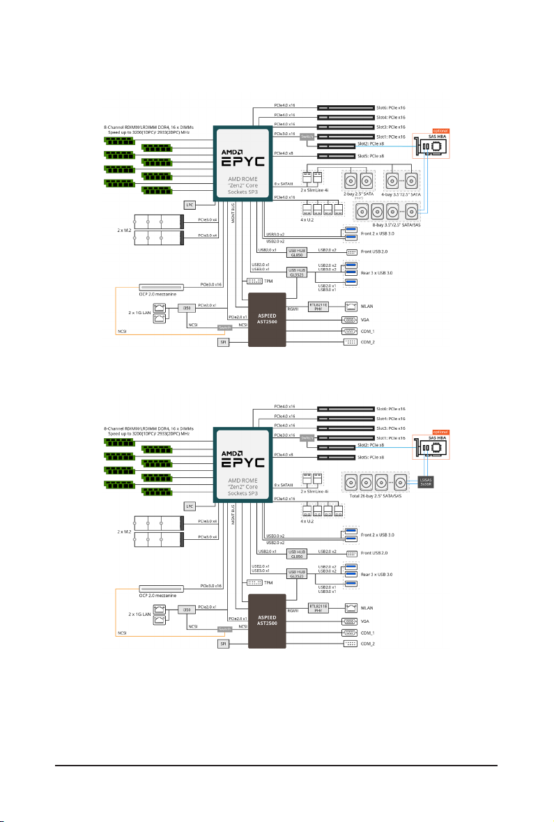
1-3 System Block Diagram
R272-Z30
R272-Z31
- 15 - Hardware Installation
Page 16
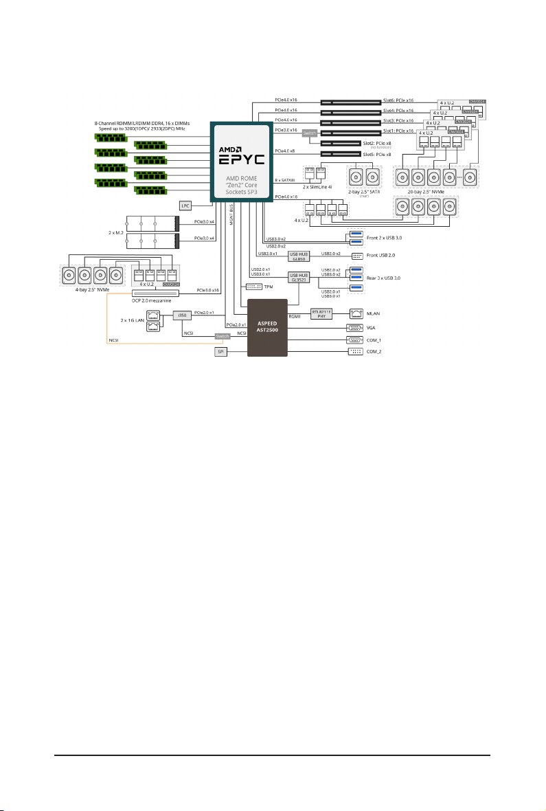
R272-Z32
- 16 - Hardware Installation
Page 17
Chapter 2 System Appearance
21
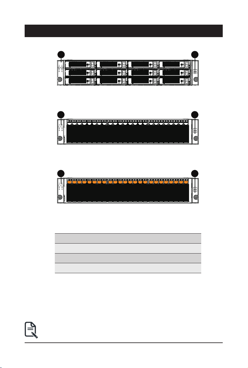
2-1 Front View
R272-Z30
R272-Z31
R272-Z32
1 2
HDD#0
HDD#1
HDD#2
HDD#0
HDD#1
HDD#0
HDD#1
HDD#2
HDD#2
HDD#3
HDD#4
HDD#5
HDD#3
HDD#4
HDD#5
HDD#6
HDD#7
HDD#8
HDD#3
HDD#4
HDD#5
HDD#6
HDD#7
HDD#8
HDD#9
HDD#10
HDD#9
HDD#10
HDD#7
HDD#8
HDD#9
HDD#11
HDD#12
HDD#13
HDD#11
HDD#12
HDD#13
HDD#15
HDD#16
HDD#14
HDD#15
HDD#16
HDD#14
HDD#10
HDD#11
HDD#12
HDD#17
HDD#18
HDD#19
HDD#17
HDD#18
HDD#19
HDD#20
HDD#21
HDD#22
HDD#20
HDD#21
HDD#22
HDD#23
HDD#23
21
No. Description
1.
2. Front USB 3.0 Port
• Please Go to Chapter
LEDs.
Front Panel LEDs and buttons
Orange HDD Latches Support NVMe
2-3 Front Panel LED
and Buttons for detail description of function
- 17 - System Appearance
Page 18
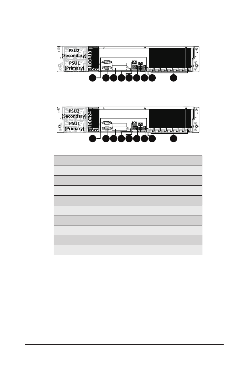
2-2 Rear View
R272-Z30
R272-Z31
R272-Z32
PSU2
(Secondary)
PSU1
(Primary)
HDD#13
HDD#14
PCIe #6
PCIe #7
PCIe #5
1 2 3 54 6 7 8 9
PSU2
(Secondary)
PSU1
(Primary)
HDD#24
HDD#25
PCIe #6
PCIe #7
PCIe #5
1 2 3 54 6 7 8 9
No. Description
1. Serial Port
2. VGA Port
3. Mezzanine Card Slot (Option/OCP V2.0 Card)
4. 10/100/1000 Server management LAN port
5. ID Button
6. USB 3.0 Port x 2
7. GbE LAN Port x 2
8. USB 3.0 Port
9. PCIe Card Slot
PCIe #3
PCIe #4
PCIe #3
PCIe #4
PCIe #1
PCIe #2
PCIe #1
PCIe #2
- 18 - System Appearance
Page 19
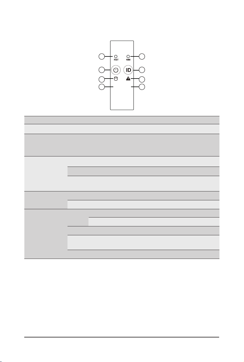
2-3 Front Panel LED and Buttons
1 2
3
5
L1
4
6
L2
87
No. Name Color Status Description
Reset Button -- -- Press this button to reset the system.
1.
Press this button for the server to generate a NMI to the
NMI button -- --
2.
Green On Indicates the system is powered on.
3.
4.
5.
Power button
with LED
ID Button
with LED
HDD Status
LED
Green Blink System is in ACPI S1 state (sleep mode).
N/A Off
Blue On Indicates the system identication is active.
N/A Off Indicates the system identication is disabled.
Green
Amber On
Green/
Amber
N/A Off
processor. If multiple-bit ECC errors occur, the server will
effectively be halted.
• System is not powered on or in ACPI S5 state (power off)
• System is in ACPI S4 state (hibernate mode)
On
Indicates locating the HDD.
Blink
Indicates accessing the HDD.
Indicates HDD error.
Blink
Indicates HDD rebuilding.
Indicates no HDD access or no HDD error.
System Appearance - 19 -
Page 20

6.
7.
8.
System
Status LED
LAN1 Active/
Link LED
LAN2 Active/
Link LED
Green On
On
Amber
Blink
N/A Off
Green On
Green Blink
N/A Off
Green
Green Blink
N/A Off
On
Indicates system is operating normally.
Indicates a critical condition, may include:
-System fan failure
-System temperature
Indicates non-critical condition, may include:
-Redundant power module failure
-Temperature and voltage issue
Indicates system is not ready, may include:
-POST error
-NMI error
-Processor or terminator is missing
Indicates a link between the system and the network or
no access.
Indicates data trasmission or receiving is occuring.
Indicates no data transmission or receiving is occuring.
Indicates a link between the system and the network or
no access.
Indicates data trasmission or receiving is occuring.
Indicates no data transmission or receiving is occuring.
System Appearance - 20 -
Page 21
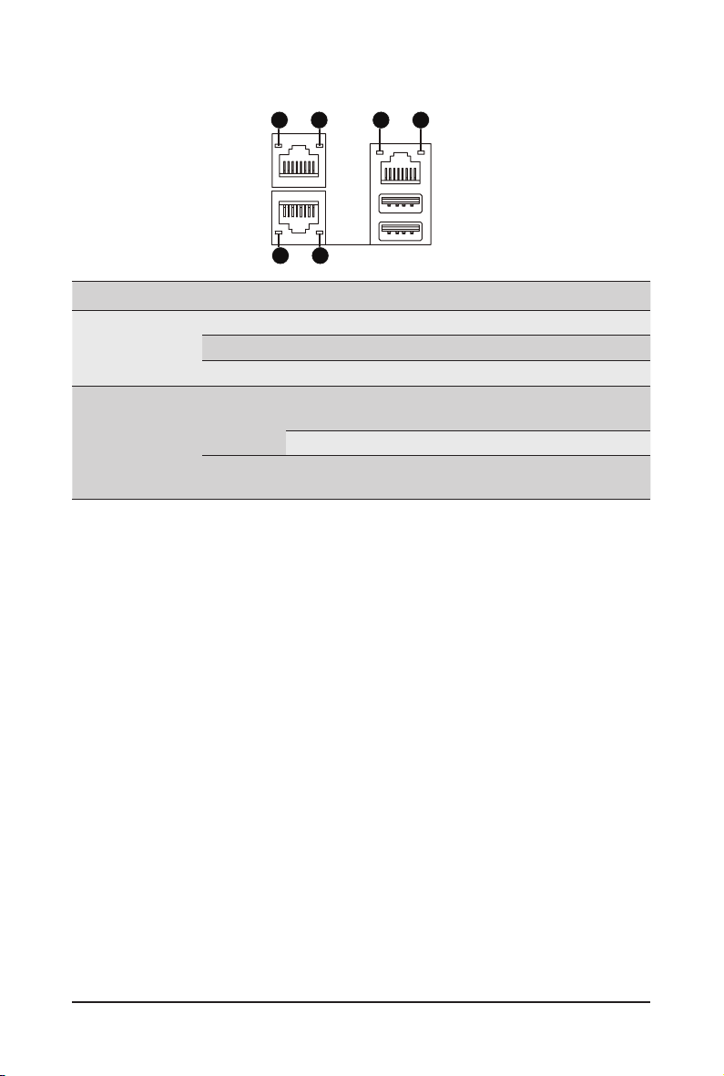
2-4 Rear System LAN LEDs
1 2
1 2
1 2
No. Name Color Status Description
Yel low On 1 Gbps data rate
Green On 100 Mbps data rate
N/A Off 10 Mbps data rate
On Link between system and
Green
network or no access
Blink Data transmission or receiving is occurring
N/A Off No data transmission or
receiving is occurring
1.
2.
1GbE
Speed LED
1GbE
Link/
Activity
LED
- 21 - System Appearance
Page 22
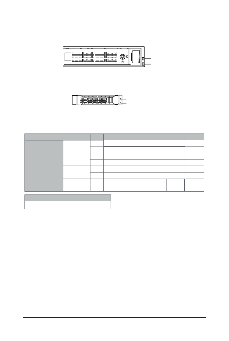
2-5 Hard Disk Drive LEDs
R272-Z30
R272-Z31
R272-Z32
RAID SKU
Disk LED
(LED on
No RAID configuration
(via HBA)
RAID configuration
(via HW RAID Card or
SW RAID Card)
LED 2
Green
Back Panel)
Removed HDD Slot
(LED on Back Panel)
Disk LED
Removed HDD Slot
HDD Present No HDD
ON
NOTE:
*1: Depends on HBA/Utility Spec.
*2: Blink cycle depends on HDD's activity signal.
*3: If HDD is pulled out during rebuilding, the disk status of this HDD is regarded as faulty.
LED1
Locate
ON(*1)
Green
Amber
ON(*1) OFF --
Green
Amber
Green
Amber
ON(*1)
Green
Amber
OFF
OFF
OFF
ON
OFF
OFF
/('
/('
HDD Fault
OFF
OFF
OFF
OFF
ON
OFF
ON
/('
/('
Rebuilding
(Low Speed: 2 Hz)
(*3)
(*3)
HDD
Access
BLINK (*2)
OFF
--
--
BLINK (*2)
OFF
--
--
HDD Present
(No Access)
OFF
OFF
--
OFF
OFF
--
--
System Appearance - 22 -
Page 23

Chapter 3 System Hardware Installation
Pre-installation Instructions
Computer components and electronic circuit boards can be damaged by discharges of static
electricity. Working on computers that are still connected to a power supply can be extremely
dangerous. Follow the simple guidelines below to avoid damage to your computer or injury to
yourself.
• Always disconnect the computer from the power outlet whenever you are working inside the
computer case.
• If possible, wear a grounded wrist strap when you are working inside the computer case.
Alternatively, discharge any static electricity by touching the bare metal system of the computer
case, or the bare metal body of any other grounded appliance.
• Hold electronic circuit boards by the edges only. Do not touch the components on the board
unless it is necessary to do so. Do not ex or stress the circuit board.
• Leave all components inside the static-proof packaging until you are ready to use the component
for the installation.
- 23 - System Hardware Installation
Page 24

3-1 Removing and Installing the Chassis Cover
1
Before you remove or install the system cover
• Make sure the system is not turned on or connected to AC power.
Follow these instructions to remove the chassis covers:
1. Remove the screw securing the back chassis cover.
2. Push down on the indentations located on the side of the chassis cover.
3. Slide the chassis cover to the rear of the system and then remove the cover in the direction of the
arrow.
4. To reinstall the chassis cover follow steps 1-3 in reverse order.
2
3
2
System Hardware Installation - 24 -
Page 25
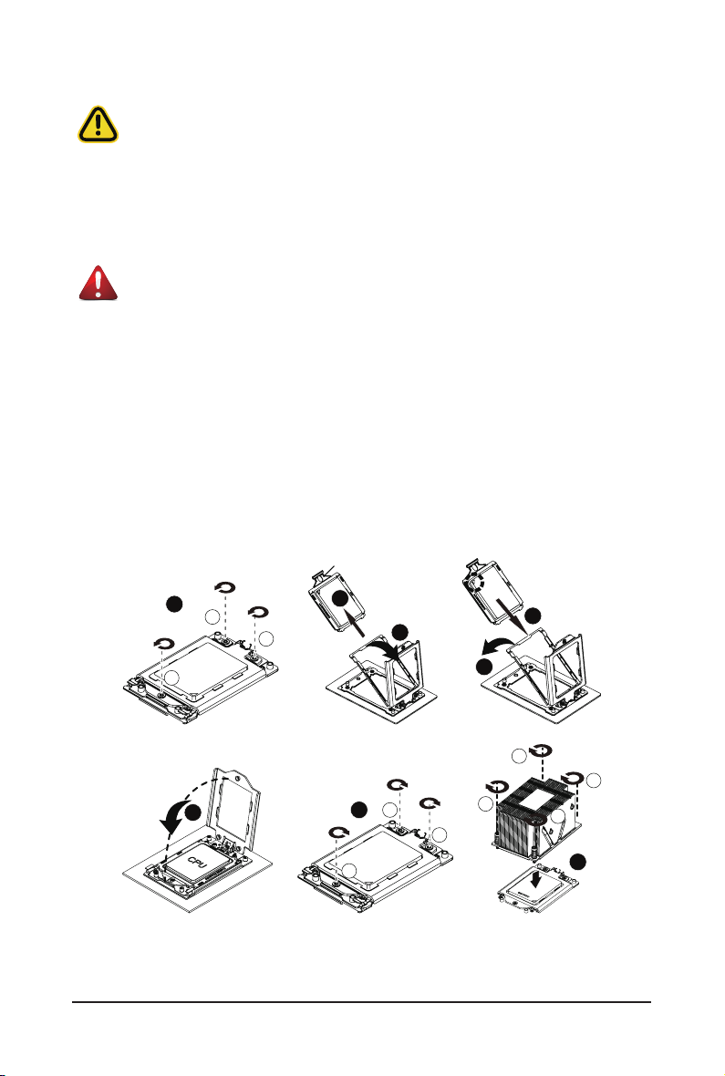
3-2 Removing and Installing the CPU and Heat Sink
External cap
Read the following guidelines before you begin to install the CPU:
• Make sure that the motherboard supports the CPU.
• Always turn off the computer and unplug the power cord from the power outlet before installing
the CPU to prevent hardware damage.
• Unplug all cables from the power outlets.
• Disconnect all telecommunication cables from their ports.
• Place the system unit on a at and stable surface.
• Open the system according to the instructions.
WARNING!
Failure to properly turn off the server before you start installing components may cause serious
damage. Do not attempt the procedures described in the following sections unless you are a
qualied service technician.
Follow these instructions to install the CPU:
1. Loosen the three captive screws in sequential order (1g2g3) securing the CPU cover.
2. Flip open the CPU cover.
3. Remove the CPU cap with CPU from the CPU frame using the handle on the CPU cap.
4. Using the handle on the CPU cap insert the new CPU cap with CPU installed into the CPU frame.
NOTE: Ensure that the CPU is installed in the CPU cap in the correct orientation, with the gold
triangle on the CPU aligned to the top left corner of the CPU cap.
5. Flip the CPU frame with CPU installed into place in the CPU socket.
3
CPU
4
5
4
1
2
3
8
1
2
1
3
6
3
2
7
2
1
- 25 - System Hardware Installation
Page 26
3-3 Removing and Installing Memory
Read the following guidelines before you begin to install the memory:
• Make sure that the motherboard supports the memory. It is recommended that memory of the
same capacity, brand, speed, and chips be used.
• Always turn off the computer and unplug the power cord from the power outlet before installing
the memory to prevent hardware damage.
• Memory modules have a foolproof design. A memory module can be installed in only one
direction. If you are unable to insert the memory, switch the direction.
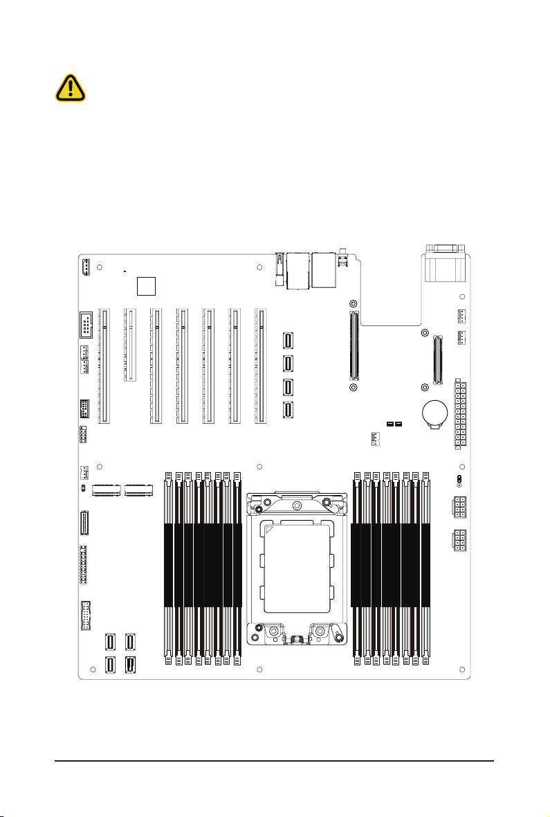
3-3-1 Six-Channel Memory Conguration
This motherboard provides 16 DDR4 memory sockets and supports Six Channel Technology. After the
memory is installed, the BIOS will automatically detect the specications and capacity of the memory.
DIMM_P0_G0
DIMM_P0_G1
DIMM_P0_H0
DIMM_P0_H1
DIMM_P0_E0
DIMM_P0_E1
DIMM_P0_F0
DIMM_P0_F1
System Hardware Installation - 26 -
CPU
DIMM_P0_A1
DIMM_P0_A0
DIMM_P0_B0
DIMM_P0_B1
DIMM_P0_D0
DIMM_P0_D1
DIMM_P0_C0
DIMM_P0_C1
Page 27
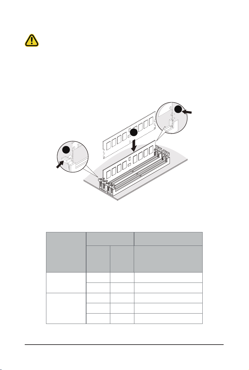
3-3-2 Removing and Installing a Memory Module
Before installing a memory module, make sure to turn off the computer and unplug the power
cord from the power outlet to prevent damage to the memory module.
Be sure to install DDR4 DIMMs on to this motherboard.
Follow these instructions to install a DIMM module:
1. Insert the DIMM memory module vertically into the DIMM slot and push it down.
2. Close the plastic clip at both edges of the DIMM slots to lock the DIMM module.
3. Reverse the installation steps when you want to remove the DIMM module.
2
1
2
3-3-3 DIMM Population Table
RDIMM Maximum Frequency Supported Tablel
DIMM
DIMMs
Populated
1R
2R
2DR
1
1
--
2
2
1
--
--
1
--
1
2
- 27 - System Hardware Installation
Frequency (MT/s)
1.2V
3200
3200
2933
2933
2933
Page 28
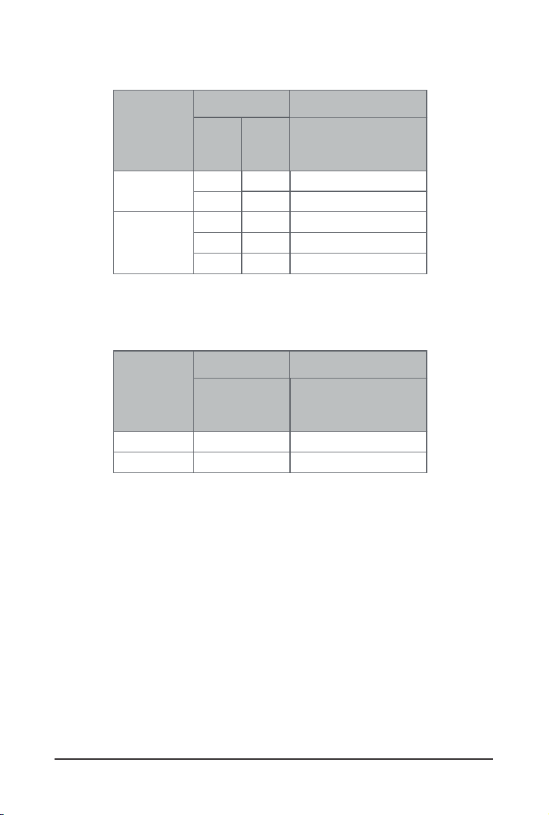
LRDIMM Maximum Frequency Supported Table
DIMM
DIMMs
Populated
1
2S2R
2S4R
4DR
1
--
2
2
1
--
3DS RDIMM Maximum Frequency Supported Table
DIMM
DIMMs
Populated
1
2
2S2R
2S4R
1
2
Frequency (MT/s)
--
1
--
1
2
Frequency (MT/s)
1.2V
3200
3200
2933
Not Supported
2933
1.2V
2933
2666
NOTE!
1R: 1 package rank of SDP DRAMs
l
2R: 2 package rank of SDP DRAMs
l
2DR: 2 package rank of DDP DRAMs
l
4DR: 4 package rank of DDP DRAMs
l
2S2R/2S4R/2S8R: 2 package rank of 2/4/8 high 3DS DRAMs
l
DIMM must be populated in sequential alphabetic order,
l
starting with bank A.
When only one DIMM is used, it must be populated in memory slot A1.
l
System Hardware Installation - 28 -
Page 29
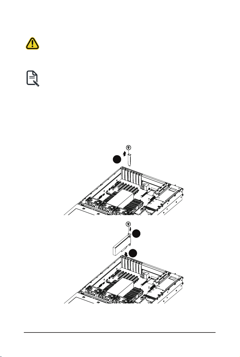
3-4 Removing and Installing the PCI Expansion Card
• Voltages can be present within the server whenever an AC power source is connected. This
voltage is present even when the main power switch is in the off position. Ensure that the system
is powered off and all power sources have been disconnected from the server prior to installing a
PCIe card.
• Failure to observe these warnings could result in personal injury or damage to equipment.
• The PCI riser assembly does not include a riser card or any cabling as standard. To install a
PCIe card, a riser card must be installed.
Follow these instructions to PCI Expansion card:
1. Remove the screw securing the riser bracket. Lift up the riser bracket out of system.
2. Loosen and remove the screw securing the slot cover from riser bracket.
3. Orient the PCIe card with the riser guide slot and push in the direction of the arrow until the PCIe
card sits in the PCIe card connector.
NOTE:
Some riser brackets allow for single or multiple PCIe cards. Repeat steps 4-5 as necessary.
4. Secure the PCIe card with the screw.
5. Reverse steps 1-3 to install the riser bracket.
1
3
2
- 29 - System Hardware Installation
Page 30
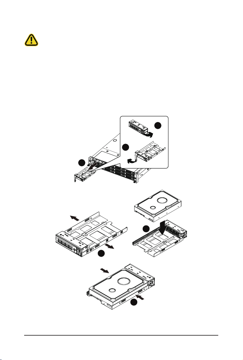
3-5 Removing and Installing the Hard Disk Drive
Read the following guidelines before you begin to install the hard disk drive:
• Take note of the drive tray orientation before sliding it out.
• The tray will not t back into the bay if it is inserted incorrectly.
• Make sure that the HDD is connected to the HDD connector on the backplane.
Follow these instructions to install a 3.5" hard disk drive:
1. Press down the colored release button.
2. Pull out the black locking lever.
3. Use the black locking lever to slide out the HDD tray.
4. Pull apart the HDD tray.
5. Slide hard disk into the tray.
6. Push together to secure the hard drive.
1
Press
2
Pull
3
Pull
Pull
4
Push
System Hardware Installation - 30 -
5
Push
6
Page 31

Follow these instructions to install a 2.5" hard disk drive:
1. Press down the colored release button.
2. Pull out the black locking lever.
3. Use the black locking lever to slide out the HDD tray.
4. Place one side of the HDD at a 45 degree angle into the tray, and align the guiding stand-offs in the
tray with the installation holes of the HDD.
5. Once aligned, push down the other side of the HDD and press it until it clicks.
2
Pull
1
Press
3
5
4
6
- 31 - System Hardware Installation
Page 32

3-6 Replacing the Fan Assembly
Follow these instructions to replace a fan assembly:
1. Flip the latches on the top of the fan outwards.
2. Using the latches, lift up the fan assembly from the chassis.
3. Reverse the previous steps to install the replacement fan assembly.
1
2
3
System Hardware Installation - 32 -
Page 33

3-7 Removing and Installing the Power Supply
Before you remove or install the power supply unit:
• Make sure the system is not turned on or connected to AC power.
Follow these instructions to replace the power supply:
1. Press the retaining clip on the left side of the power supply unit along the direction of the arrow.
2. Pull the power supply handle at the same time and pull out the power supply unit.
3. Insert the replacement power supply unit rmly into the chassis. Connect the AC power cord to the
replacement power supply.
4. Repeat steps 1-3 for replacement of the second power supply.
3
2
1
- 33 - System Hardware Installation
Page 34

3-8 Installing the Mezzanine Card (Optional)
Follow these instructions to install a mezzanine card:
1. Insert the mezzanine card into the system ensuring that the connector on the mezzanine card
connects to the connector on the motherboard.
2. Secure the mezzanine card to the system with three screws.
NOTE! Supports OCP V2.0 Card.
2
1
System Hardware Installation - 34 -
Page 35

3-9 Cable Routing
3-9-1 R272-Z30 Cable Routing
Front Switch Cable/Front LED Cable Front Panel USB 3.0 Cable
HDD Back Plane Board Power Cable HDD Back Plane Board Signal Cable
- 35 - System Hardware Installation
Page 36

Rear HDD Back Panel Board SATA Cable Rear HDD Back Panel Board Signal Cable
On-Board SATA to HDD Back Panel Board
Cable
System Hardware Installation - 36 -
HBA Cable
Page 37

3-9-2 R272-Z31 Cable Routing
Front Switch Cable/Front LED Cable Front Panel USB 3.0 Cable
HDD Back Plane Board Power Cable HDD Back Plane Board Signal Cable
- 37 - System Hardware Installation
Page 38

Rear HDD Back Panel Board SATA Cable Rear HDD Back Panel Board Signal Cable
SAS Expander Card to HDD Back Panel
Board Cable #1
System Hardware Installation - 38 -
SAS Expander Card to HDD Back Panel
Board Cable #2
Page 39

HBA Card to SAS Expander Card Cable
- 39 - System Hardware Installation
Page 40

3-9-3 R272-Z32 Cable Routing
Front Switch Cable/Front LED Cable Front Panel USB 3.0 Cable
HDD Back Plane Board Power Cable HDD Back Plane Board Signal Cable
System Hardware Installation - 40 -
Page 41

Rear HDD Back Panel Board SATA Cable
Rear HDD Back Panel Board Signal Cable
NVMe Expander Card Cable #0-#3 NVMe Expander Card Cable #4-#7
- 41 - System Hardware Installation
Page 42

NVMe Expander Card Cable #8-#11
NVMe Expander Card Cable #12-#15
NVMe Expander Card Cable #16-#19
System Hardware Installation - 42 -
NVMe Expander Card Cable #20-#23
Page 43

Chapter 4 Motherboard Components
4-1 Motherboard Components
14
13
12
2015 16 17 18 19 21
22
23
11
10
24
25
26
27
26
28
89
7
6
DIMM_P0_G0
DIMM_P0_G1
DIMM_P0_H0
DIMM_P0_H1
DIMM_P0_E0
DIMM_P0_E1
DIMM_P0_F0
DIMM_P0_F1
CPU
5
34
1
Item Description
1 SlimLine SAS Connector (U2_0)
2 SlimLine SAS Connector (U2_1)
3 SlimLine SAS Connector (U2_2)
4 SlimLine SAS Connector (U2_3)
5 Front Panel USB 3.0 Connector
6 Front Panel Connector
7 HDD Back Plane Board Connector
8 M.2 Connector (PCIe3 x4, NGFF-2280)
9 Riser Connector #1
2
- 43 - Motherboard Components
DIMM_P0_A1
DIMM_P0_A0
DIMM_P0_B0
DIMM_P0_B1
DIMM_P0_D0
DIMM_P0_D1
DIMM_P0_C0
DIMM_P0_C1
29
30
31
32
Page 44

10 M.2 Connector (PCIe3 x4, NGFF-2280)
11 USB 2.0 Cable Connector
12 TPM Module Connector
13 Serial Port Cable ConnectorIPMB Connector
14 BMC Firmware Readiness LED
15 PCIe x16 Slot #1
16 PCIe x8 Slot #2
17 PCIe x16 Slot #3
18 PCIe x16 Slot #4
19 PCIe x16 Slot #5 (x8 Signal)
20 PCIe x 16 Slot #6
21 PCIe x16 Slot #7
22 SlimLine SAS Connector (SLINK0)
23 SlimLine SAS Connector (SLINK1)
24 SlimLine SAS Connector (SLINK2)
25 SlimLine SAS Connector (SLINK3)
26* OCP Mezzanine Connector
27 System Battery
28 2 x 13 Pin Power Connector
29 2 x 4 Pin 12V Power Connector
30 2 x 4 Pin 12V Power Connector
31 SlimLine SAS Connector (SATA0)
32 SlimLine SAS Connector (SATA1)
NOTE!
Motherboard Components - 44 -
Supports OCP V2.0 Card.
Page 45

4-2 Jumper Settings
-
21',3
J2
HSMB_SEL
1
PMBUS_SEL
2
3
BIOS_PWD
4
BIOS_RCVR
Clear supervisor password
ON
BIOS Defined
BIOS Defined
BIOS recovery mode
OFF
Normal [Default]
Normal [Default]
Clear CMOS
CLR_CMOS
- 45 - Motherboard Components
1
2
3
Default
Enable
Page 46

This page intentionally left blank
Motherboard Components - 46 -
Page 47

Chapter 5 BIOS Setup
BIOS (Basic Input and Output System) records hardware parameters of the system in the EFI on the
motherboard. Its major functions include conducting the Power-On Self-Test (POST) during system startup,
saving system parameters and loading operating system, etc. BIOS includes a BIOS Setup program that
allows the user to modify basic system conguration settings or to activate certain system features. When the
power is turned off, the battery on the motherboard supplies the necessary power to the CMOS to keep the
conguration values in the CMOS.
To access the BIOS Setup program, press the <DEL> key during the POST when the power is turned on.
• BIOS ashing is potentially risky, if you do not encounter problems of using the current BIOS
version, it is recommended that you don't ash the BIOS. To ash the BIOS, do it with caution.
Inadequate BIOS ashing may result in system malfunction.
• It is recommended that you not alter the default settings (unless you need to) to prevent system
instability or other unexpected results. Inadequately altering the settings may result in system's
failure to boot. If this occurs, try to clear the CMOS values and reset the board to default values.
(Refer to the Exit section in this chapter or introductions of the battery/clearing CMOS jumper in
Chapter 1 for how to clear the CMOS values.)
BIOS Setup Program Function Keys
<f><g> Move the selection bar to select the screen
<h><i> Move the selection bar to select an item
<+> Increase the numeric value or make changes
<-> Decrease the numeric value or make changes
<Enter> Execute command or enter the submenu
<Esc> Main Menu: Exit the BIOS Setup program
Submenus: Exit current submenu
<F1> Show descriptions of general help
<F3> Restore the previous BIOS settings for the current submenus
<F9> Load the Optimized BIOS default settings for the current submenus
<F10> Save all the changes and exit the BIOS Setup program
- 47 - BIOS Setup
Page 48

Main
This setup page includes all the items in standard compatible BIOS.
Advanced
This setup page includes all the items of AMI BIOS special enhanced features.
(ex: Auto detect fan and temperature status, automatically congure hard disk parameters.)
AMD CBS
This setup page includes the common items for conguration of AMD motherboard-related information.
AMD PBS Option
This setup page includes the common items for conguration of AMD CPM RAS related settings.
Chipset
This setup page includes all the submenu options for conguring the function of processor, network,
North Bridge, South Bridge, and System event logs.
Server Management
Server additional features enabled/disabled setup menus.
Security
Change, set, or disable supervisor and user password. Conguration supervisor password allows you to
restrict access to the system and BIOS Setup.
A supervisor password allows you to make changes in BIOS Setup.
A user password only allows you to view the BIOS settings but not to make changes.
Boot
This setup page provides items for conguration of boot sequence.
Save & Exit
Save all the changes made in the BIOS Setup program to the CMOS and exit BIOS Setup. (Pressing
<F10> can also carry out this task.)
Abandon all changes and the previous settings remain in effect. Pressing <Y> to the confirmation
message will exit BIOS Setup. (Pressing <Esc> can also carry out this task.)
BIOS Setup - 48 -
Page 49

5-1 The Main Menu
Once you enter the BIOS Setup program, the Main Menu (as shown below) appears on the screen. Use
arrow keys to move among the items and press <Enter> to accept or enter other sub-menu.
Main Menu Help
The on-screen description of a highlighted setup option is displayed on the bottom line of the Main Menu.
Submenu Help
While in a submenu, press <F1> to display a help screen (General Help) of function keys available for the
menu. Press <Esc> to exit the help screen. Help for each item is in the Item Help block on the right side of
the submenu.
• When the system is not stable as usual, select the Restore Defaults item to set your system
to its defaults.
• The BIOS Setup menus described in this chapter are for reference only and may differ by
BIOS version.
Parameter Description
BIOS Information
Project Name Displays the project name information.
Project Version Displays version number of the BIOS setup utility.
Build Date and Time Displays the date and time when the BIOS setup utility was created.
BMC Information
BMC Firmware Version Displays version number of the BIOS setup utility.
- 49 - BIOS Setup
Page 50

Parameter Description
Onboard LAN Information
LAN1 MAC Address
LAN2 MAC Address
(Note1)
(Note1)
Displays LAN MAC address information.
Displays LAN MAC address information.
VR Information
Version Displays VR version information.
AGESA PI Version
PI Version Displays AGESA PI version information.
Memory Information
Total Memory
Memory Frequency
(Note2)
(Note2)
Displays the total memory size of the installed memory.
Displays the frequency information of the installed memory.
System Date Sets the date following the weekday-month-day-year format.
System Time Sets the system time following the hour-minute-second format.
(Note1) The number of LAN ports listed will depend on the motherboard / system model.
(Note2) This section will display capacity and frequency information of the memory that the customer
has installed.
BIOS Setup - 50 -
Page 51

5-2 Advanced Menu
The Advanced menu display submenu options for conguring the function of various hardware components.
Select a submenu item, then press [Enter] to access the related submenu screen.
- 51 - BIOS Setup
Page 52

5-2-1 Trusted Computing
Parameter Description
Conguration
Security Device Support
SPI TPM Support Options available: Enabled/Disabled. Default setting is Enabled
Disable Block Sid Options available: Enabled/Disabled. Default setting is Disabled.
Select Enabled to activate TPM support feature.
Options available: Enabled/Disabled. Default setting is Disabled.
BIOS Setup - 52 -
Page 53

5-2-2 PSP Firmware Versions
The PSP Firmware Versions page displays the basic PSP rmware version information. Items on this window
are non-congurable.
- 53 - BIOS Setup
Page 54

5-2-3 Legacy Video Select
Parameter Description
OnBrd/Ext VGA Select
Select between onboard or external VGA support.
Options available: Auto/Onboard/External. Default setting is Onboard.
BIOS Setup - 54 -
Page 55

5-2-4 AST2500 Super IO Conguration
Parameter Description
AST2500 Super IO
Conguration
Super IO Chip
Serial Port 1/2
Conguration
Press [Enter] for conguration of advanced items.
- 55 - BIOS Setup
Page 56

5-2-4-1 Serial Port 1/2 Conguration
BIOS Setup - 56 -
Page 57

Parameter Description
Serial Port 1/2
Conguration
Enable/Disable the Serial Port (COM). When set to Enabled allows you to
Serial Port
(Note1)
congure the Serial port 1/2 settings. When set to Disabled, displays no
conguration for the serial port.
Options available: Enabled/Disabled. Default setting is Enabled.
Devices Settings
(Note2)
Displays the Serial Port 1/2 device settings.
Select an optimal settings for Super IO Device.
Options available for Serial Port 1:
Auto
IO=3F8h; IRQ=4;
IO=3F8h; IRQ=3, 4, 5, 6, 7, 9, 10, 11, 12;
IO=2F8h; IRQ=3, 4, 5, 6, 7, 9, 10, 11, 12;
IO=3E8h; IRQ=3, 4, 5, 6, 7, 9, 10, 11, 12;
IO=2E8h; IRQ=3, 4, 5, 6, 7, 9, 10, 11, 12;
Default setting is Auto.
Change Settings
(Note2)
Options available for Serial Port 2:
Auto
IO=2F8h; IRQ=3;
IO=3F8h; IRQ=3, 4, 5, 6, 7, 9, 10, 11, 12;
IO=2F8h; IRQ=3, 4, 5, 6, 7, 9, 10, 11, 12;
IO=3E8h; IRQ=3, 4, 5, 6, 7, 9, 10, 11, 12;
IO=2E8h; IRQ=3, 4, 5, 6, 7, 9, 10, 11, 12;
Default setting is Auto.
Please note that this item is congurable when Serial Port is set to
Enabled.
(Note1) Advanced items prompt when this item is dened.
(Note)
(Note2) This item appears when Serial Port is set to Enabled.
- 57 - BIOS Setup
Page 58

5-2-5 S5 RTC Wake Settings
Parameter Description
Enable or disable System wake on alarm event. When enabled, System
Wake system from S5
Wake up year Press <+> and <-> to dene the wake up year.
Wake up month Press <+> and <-> to dene the wake up month.
Wake up Date Press <+> and <-> to dene the wake up date.
Wake up hour Press <+> and <-> to dene the wake up hour.
Wake up minute Press <+> and <-> to dene the wake up minute.
Wake up second Press <+> and <-> to dene the wake up second.
(Note)
will wake on the hr:min:sec specied.
Default setting is
Disabled
.
(Note) This item appears when
Wake system from S5
BIOS Setup - 58 -
is set to
Enabled
.
Page 59

5-2-6 Serial Port Console Redirection
Parameter Description
Select whether to enable console redirection for specied device. Console
COM1/COM2 Serial Over
LAN Console Redirection
Legacy Console Redirection
Serial Port for Out-of-Band
Management / Windows
Emergency Management
Services (EMS) Console
Redirection
(Note)
COM1/COM2 Serial LAN/
Legacy/Serial Port for Outof-Band EMS Console
Redirection Settings
redirection enables the users to manage the system from a remote
(Note)
location.
Options available: Enabled/Disabled. Default setting is Disabled.
Selects a COM port for Legacy serial redirection. The options are
dependent on the available COM ports.
Selects a COM port for EMS console redirection. EMS console redirection
allows the user to congure Console Redirection Settings to support Out-
of-Band Serial Port management.
Options available: Enabled/Disabled. Default setting is Disabled.
Press [Enter] to congure advanced items.
Please note that this item is congurable when COM1 Serial Over
LAN/Serial Port for Out-of-Band Management EMS Console Redirec-
tion is set to Enabled.
Terminal Type
– Selects a terminal type to be used for console redirection.
– Options available: VT100/VT100+/ANSI /VT-UTF8. Default setting
is ANSI.
(Note) Advanced items prompt when this item is dened.
- 59 - BIOS Setup
Page 60

Parameter Description
Bits per second
– Selects the transfer rate for console redirection.
– Options available: 9600/19200/38400/57600/115200. Default
setting is 115200.
Data Bits
– Selects the number of data bits used for console redirection.
– Options available: 7/8. Default setting is 8.
Parity
– A parity bit can be sent with the data bits to detect some
transmission errors.
– Even: parity bit is 0 if the num of 1's in the data bits is even.
– Odd: parity bit is 0 if num of 1's in the data bits is odd.
– Mark: parity bit is always 1. Space: Parity bit is always 0.
– Mark and Space Parity do not allow for error detection.
– Options available: None/Even/Odd/Mark/Space. Default setting is
None.
Stop Bits
COM1/COM2 Serial LAN/
Legacy/Serial Port for Outof-Band EMS Console
Redirection Settings
(continued)
– Stop bits indicate the end of a serial data packet. (A start bit
indicates the beginning). The standard setting is 1 stop bit.
Communication with slow devices may require more than 1 stop
bit.
– Options available: 1/2. Default setting is 1.
Flow Control
– Flow control can prevent data loss from buffer overow. When
sending data, if the receiving buffers are full, a 'stop' signal can
be sent to stop the data ow. Once the buffers are empty, a 'start'
signal can be sent to re-start the ow. Hardware ow control uses
two wires to send start/stop signals.
– Options available: None/Hardware RTS/CTS. Default setting is
None.
VT-UTF8 Combo Key Support
– Enable/Disable the VT-UTF8 Combo Key Support.
– Options available: Enabled/Disabled. Default setting is Enabled.
Recorder Mode
– When this mode enabled, only texts will be send. This is to capture
Terminal data.
– Options available: Enabled/Disabled. Default setting is Disabled.
Resolution 100x31
– Enable/Disable extended terminal resolution.
– Options available: Enabled/Disabled. Default setting is Enabled.
(Note)
(Note)
(Note) Advanced items prompt when this item is dened.
BIOS Setup - 60 -
Page 61

5-2-7 CPU Conguration
Parameter Description
SVM Mode
SMEE
CPU 0 Information Press [Enter] to view the memory information related to CPU 0.
Enable/disable the CPU Virtualization.
Options available: Enabled/Disabled. Default setting is Enabled.
Controls the Secure Memory Encryption Enable (SMEE) function.
Options available: Enabled/Disabled. Default setting is Enabled.
- 61 - BIOS Setup
Page 62

5-2-7-1 CPU 0 Information
BIOS Setup - 62 -
Page 63

5-2-8 PCI Subsystem
Parameter Description
PCI Bus Driver Version Displays the PCI Bus Driver version information.
Change the PCIe lanes.
Options available: Auto/x16/x8x8/x8x4x4/x4x4x8/x4x4x4x4/
Disabled. Default setting is Auto.
PCIE_#
(Note1)
PCI Express Slot # I/O ROM
(Note1)
ROM for the related PCI-E slot.
Options available: Enabled/Disabled. Default setting is Enabled.
Change mezzanine PCIe lanes.
When enabled, this setting will initialize the device expansion
MEZZ
Options available: Auto/x16/x8x8/x8x4x4/x4x4x8/x4x4x4x4/
Disabled. Default setting is Auto.
When enabled, this setting will initialize the device expansion
MEZZ I/O ROM
ROM for the related U.2 device.
Options available: Enabled/Disabled. Default setting is Enabled.
Enable/Disable the onboard LAN1 / LAN2 devices.
Onboard LAN1 / LAN2 Controller
(Note2)
Options available: Enabled/Disabled. Default setting is Enabled.
Enable/Disable the onboard LAN1 / LAN2 devices, and initializes
Onboard LAN1 / LAN2 I/O ROM
(Note2)
device expansion ROM.
Options available: Enabled/Disabled. Default setting is Enabled.
(Note1) This section is dependent on the available PCIe Slot.
(Note2) This section is dependent on the available LAN controller.
- 63 - BIOS Setup
Page 64

Parameter Description
PCI Devices Common Settings
Enable/Disable memory mapped I/O to 4GB or greater address
Above 4G Decoding
SR-IOV Support
PCI-E AER Enabled Options available: Enabled/Disabled. Default setting is Disabled
space (Above 4G Decoding).
Options available: Enabled/Disabled. Default setting is Enabled.
If the system has SR-IOV capable PCIe devices, this item
Enable/Disable Single Root IO Virtualization Support.
Options available: Enabled/Disabled. Default setting is Enabled.
BIOS Setup - 64 -
Page 65

5-2-9 USB Conguration
Parameter Description
USB Conguration
USB Controller Displays the supported USB controllers.
USB Devices: Displays the USB devices connected to the system.
Enable/disable the Legacy USB support fuction. AUTO option disables
Legacy USB Support
XHCI Hand-off
USB Mass Storage Driver
(Note)
Support
Port 60/64 Emulation
USB hardware delays and
time-outs
USB transfer time out
Device reset time out
legacy support if no USB devices are connected. DISABLE option will
keep USB devices available only for EFI applications.
Options available: Auto/Enabled/Disabled. Default setting is Enabled.
Enable/Disable the XHCI (USB 3.0) Hand-off support.
Options available: Enabled/Disabled. Default setting is Enabled.
Enable/Disable the USB Mass Storage Driver Support.
Options available: Enabled/Disabled. Default setting is Enabled.
Enables the I/O port 60h/64h emulation support. This should be enabled
for the complete USB Keyboard Legacy support for non-USB aware OS.
Options available: Enabled/Disabled. Default setting is Enabled.
The time-out value for Control, Bulk, and Interrupt transfers.
Options available: 1 sec/5 sec/10 sec/20 sec. Default setting is 20 sec.
USB mass storage device Start Unit command time-out.
Options available: 10 sec/20 sec/30 sec/40 sec. Default setting is 20 sec.
(Note) This item is present only if you attach USB devices.
- 65 - BIOS Setup
Page 66

Maximum time the device will take before it properly reports itself to the
Host Controller. "Auto" uses default value: for a Root port it is 100
Device power-up delay
Mass Storage Devices Displays the mass storage devices avaiable on the system.
ms, for a Hub port the delay is taken from Hub descriptor.
Options available: Auto/Manual. Default setting is Auto.
BIOS Setup - 66 -
Page 67

5-2-10 NVMe Conguration
Parameter Description
NVMe controller and Drive
Information
Displays the NVMe devices connected to the system.
- 67 - BIOS Setup
Page 68

5-2-11 SATA Conguration
BIOS Setup - 68 -
Page 69

5-2-12 Network Stack
Parameter Description
Network Stack
Ipv4 PXE Support
Ipv4 HTTP Support
Ipv6 PXE Support
Ipv6 HTTP Support
IPSEC Certicate
Media detect count
(Note)
(Note)
(Note)
(Note)
(Note)
(Note)
Enable/Disable the UEFI network stack.
Options available: Enabled/Disabled. Default setting is Enabled.
Enable/Disable the Ipv4 PXE feature.
Options available: Enabled/Disabled. Default setting is Enabled.
Enable/Disable the Ipv4 HTTP feature.
Options available: Enabled/Disabled. Default setting is Disabled.
Enable/Disable the Ipv6 PXE feature.
Options available: Enabled/Disabled. Default setting is Disabled.
Enable/Disable the Ipv6 HTTP feature.
Options available: Enabled/Disabled. Default setting is Disabled.
Enable/Disable the IPSEC Certicate feature.
Press the <+> / <-> keys to increase or decrease the desired values.
(Note) This item appears when Network Stack is set to Enabled.
- 69 - BIOS Setup
Page 70

5-2-13 AMD Mem Conguration Status
Parameter Description
CPU0 Press [Enter] for conguration of advanced items.
BIOS Setup - 70 -
Page 71

5-2-14 iSCSI Conguration
Parameter Description
iSCSI Initiator Name
Add Attempt Press [Enter] for conguration of advanced items.
Delete Attempt Press [Enter] for conguration of advanced items.
Change Attempt Order Press [Enter] for conguration of advanced items.
- 71 - BIOS Setup
Page 72

5-2-15 Tls Auth Conguration
Parameter Description
Save CA Conguration Press [Enter] for conguration of advanced items.
Client Cert Conguration Press [Enter] for conguration of advanced items.
BIOS Setup - 72 -
Page 73

5-2-16 AVAGO MegaRAID Conguration Utility
- 73 - BIOS Setup
Page 74

Parameter Description
Main Menu Press [Enter] for conguration of advanced items.
Help Press [Enter] for conguration of advanced items.
PROPERTIES
Status
Current Personality
Backplane
BBU
Enclosure
Drives
Drive Gropus
Virtual Drives
View Server Prole Press [Enter] for conguration to view Server Prole.
Action
Congure Press [Enter] for conguration of advanced items.
Set Factory Defaults Press [Enter] to active this function.
Update Firmware Press [Enter] to active this function.
Silience Alarm Press [Enter] to active this function.
BACKGROUND
OPERATIONS in Progress
MegaRAID ADVANCED
SOFTWARE OPTIONS
MegaRAID RAID6
MegaRAID RAID5
MegaRAID FastPath
Manage MegaRAID Advanced
Software Options
Press [Enter] for conguration of advanced items.
BIOS Setup - 74 -
Page 75

5-2-17 Intel(R) I350 Gigabit Network Connection
- 75 - BIOS Setup
Page 76

Parameter Description
Press [Enter] to congure advanced items.
Link Speed
– Allows for automatic link speed adjustment.
– Options available: Auto Negotiated/10 Mbps Half/10 Mbps Full/100
Mbps Half/100 Mbps Full. Default setting is Auto Negotiated.
NIC Conguration
Blink LEDs
UEFI Driver Displays the technical specications for the Network Interface Controller.
Adapter PBA Displays the technical specications for the Network Interface Controller.
Device Name Displays the technical specications for the Network Interface Controller.
Chip Type Displays the technical specications for the Network Interface Controller.
PCI Device ID Displays the technical specications for the Network Interface Controller.
PCI Address Displays the technical specications for the Network Interface Controller.
Link Status Displays the technical specications for the Network Interface Controller.
MAC Address Displays the technical specications for the Network Interface Controller.
Virtual MAC Address Displays the technical specications for the Network Interface Controller.
Wake On LAN
– Enables power on of the system via LAN. Note that conguring
Wake on LAN in the operating system does not change the value
of this setting, but does override the behavior of Wake on LAN in
OS controlled power states.
– Options available: Enabled/Disabled. Default setting is Enabled.
Identies the physical network port by blinking the associated LED.
Press the numeric keys to adjust desired values.
BIOS Setup - 76 -
Page 77

5-2-18 VLAN Conguration
- 77 - BIOS Setup
Page 78

Parameter Description
Press [Enter] to congure advanced items.
Create new VLAN
VLAN ID
– Sets VLAN ID for a new VLAN or an existing VLAN.
– Press the <+> / <-> keys to increase or decrease the desired values.
– The valid range is from 0 to 4094.
Priority
– Sets 802.1Q Priority for a new VLAN or an existing VLAN.
Enter Conguration Menu
– Press the <+> / <-> keys to increase or decrease the desired values.
– The valid range is from 0 to 7.
Add VLAN
– Press [Enter] to create a new VLAN or update an existing VLAN.
Congured VLAN List
– Enable/Disable the VLAN.
– Options available: Enable/Disable. Default setting is Disable.
Remove VLAN
– Press [Enter] to remove an existing VLAN.
(Note) Only Supported when Congured VLAN List is set to Enabled.
BIOS Setup - 78 -
Page 79

5-2-19 MAC IPv4 Network Conguration
Parameter Description
Congured Options available: Enabled/Disabled. Default setting is Enabled.
Enable DHCP Options available: Enabled/Disabled. Default setting is Enabled.
Local IP Address Press [Enter] to congure local IP address.
Local NetMask Press [Enter] to congure local NetMask.
Local Gateway Press [Enter] to congure local Gateway
Local DNS Servers Press [Enter] to congure local DNS servers
Save Changes and Exit Press [Enter] save all congurations.
- 79 - BIOS Setup
Page 80

5-2-20 MAC IPv6 Network Conguration
Parameter Description
Enter Conguration Menu Press [Enter] for conguration of advanced items.
BIOS Setup - 80 -
Page 81

5-3 AMD CBS Menu
AMD CBS menu displays submenu options for configuring the CPU-related information that the BIOS
automatically sets. Select a submenu item, then press [Enter] to access the related submenu screen.
- 81 - BIOS Setup
Page 82

5-3-1 Valhalla Common Options
Parameter Description
Performance Press [Enter] for conguration of advanced items.
Prefetcher settings Press [Enter] for conguration of advanced items.
Core Watchdog Press [Enter] for conguration of advanced items.
RedirectForReturnDis Options available: Auto/1/0. Default setting is Auto.
Platform First Error Warning Options available: Auto/Enabled/Disabled. Default setting is Auto.
Core Performance Boost Options available: Auto/Disabled. Default setting is Auto.
Global C-State Control Options available: Auto/Enabled/Disabled. Default setting is Auto.
Power Supply Idle Control
Opcache Control Options available: Auto/Enabled/Disabled. Default setting is Auto.
SEV ASID Count Options available: Auto/253 ASIDs/509 ASIDs. Default setting is Auto.
SEV-ES ASID Space Limit
Control
Streaming Stores Control Options available: Auto/Enabled/Disabled. Default setting is Auto.
ACPI_CST C1 Decaration Options available: Auto/Enabled/Disabled. Default setting is Auto.
Local APIC Mode Options available: Auto/xAPIC/x2APIC. Default setting is Auto.
MCA error thresh enable Options available: Auto/False/True. Default setting is Auto.
Options available: Auto/Low Current Idle/Typical Current Idle. Default
setting is Auto.
Options available: Auto/Manual. Default setting is Auto.
BIOS Setup - 82 -
Page 83

Parameter Description
SMU and PSP Debug Mode Options available: Auto/Enabled/Disabled. Default setting is Auto.
Xtrig7 Workaround
PPIN Opt-in Options available: Auto/Enabled/Disabled. Default setting is Auto.
Options available: Auto/No Workaround/ Bronze Workaround/ Sliver
Workaround. Default setting is Auto.
- 83 - BIOS Setup
Page 84

5-3-2 DF Common Options
Parameter Description
Scrubber Press [Enter] for conguration of advanced items.
Memory Addressing Press [Enter] for conguration of advanced items.
ACPI Press [Enter] for conguration of advanced items.
Link Press [Enter] for conguration of advanced items.
Disable DF to external IP
sync ood propagation
Disable DF sync ood
propagation
Frezze DF module queues on
error
CC6 memory region
encryption
System probe lter Options available: Auto/Enabled/Disabled. Default setting is Auto.
Memory Clear Options available: Auto/Enabled/Disabled. Default setting is Auto.
PSP error injection support Options available: False/True. Default setting is False.
Options available: Auto/Sync ood disabled/Sync ood enabled. Default
setting is Auto.
Options available: Auto/Sync ood disabled/Sync ood enabled. Default
setting is Auto.
Options available: Auto/Enabled/Disabled. Default setting is Auto.
Options available: Auto/Enabled/Disabled. Default setting is Auto.
BIOS Setup - 84 -
Page 85

5-3-3 UMC Common Options
Parameter Description
DDR4 Common Options Press [Enter] for conguration of advanced items.
DRAM Memory Mapping Press [Enter] for conguration of advanced items.
NVDIMM Press [Enter] for conguration of advanced items.
Memory MBIST Press [Enter] for conguration of advanced items.
- 85 - BIOS Setup
Page 86

5-3-3-1 DDR4 Common Options
Parameter Description
Enforce POR Press [Enter] to congure the enforce POR.
DRAM Controller
Conguration
CAD Bus Conguration Press [Enter] to congure the cad bus.
Data Bus Conguration Press [Enter] to congure the data bus.
Common RAS Press [Enter] to congure the common RAS.
Security Press [Enter] to congure security.
Press [Enter] to congure the DRAM controller.
BIOS Setup - 86 -
Page 87

5-3-3-2 DRAM Memory Mapping
Parameter Description
Chipselect Interleaving
BankGroupSwap
BankGroupSwapAlt Options available: Enabled/Disabled/Auto. Default setting is Auto.
Address Hash Bank Options available: Enabled/Disabled/Auto. Default setting is Auto.
Address Hash CS Options available: Enabled/Disabled/Auto. Default setting is Auto.
Address Hash Rm Options available: Enabled/Disabled/Auto. Default setting is Auto.
SPD Read Optimization
Interleave memory blocks across the DRAM chip selects for CPU 0.
Options available: Disabled/Auto. Default setting is Auto.
Congures the BankGroupSwap. BankGroupSwap (BGS) is a new
memory mapping option in AGESA that alters how applications get
assigned to physical locations within the memory modules. When this
option sets to Auto, it is null: No help string.
Options available: Enabled/Disabled/Auto. Default setting is Auto.
Enable or disable SPD Read Optimization.
Options available: Enabled/Disabled/Auto. Default setting is Auto.
- 87 - BIOS Setup
Page 88

5-3-3-3 NVDIMM
BIOS Setup - 88 -
Page 89

5-3-3-4 Memory MBIST
Parameter Description
MBIST Enable Options available: Enabled/Disabled. Default setting is Disabled.
MBIST Test Mode
MBIST Aggressors
(Note)
(Note)
MBIST Per Bit Slave Die
(Note)
Reporting
Data Eye Press [Enter] for conguration of advanced items.
Options available: Interface Mode/Data Eye Mode/Both/Auto. Default
setting is Auto.
Options available: Auto/Enabled/Disabled. Default setting is Auto.
Options available: Auto/Enabled/Disabled. Default setting is Auto.
(Note) This item appears when MBIST Enable is set to Enabled.
- 89 - BIOS Setup
Page 90

5-3-4 NBIO Common Options
Parameter Description
IOMMU Options available: Enabled/Disabled. Default setting is Disabled.
ACS Enable Options available: Auto/Enabled/Disabled. Default setting is Auto.
PCIe ARI Support Options available: Auto/Enabled/Disabled. Default setting is Auto.
PCIe Ten Bit Tag Support Options available: Auto/Enabled/Disabled. Default setting is Auto.
HD Audio Enable Press [Enter] for conguration of advanced items.
SMU Common Options Press [Enter] for conguration of advanced items.
NBIO RAS Common Options Press [Enter] for conguration of advanced items.
Enable AER Cap Options available: Auto/Enabled/Disabled. Default setting is Auto.
Early Link Speed Options available: Auto/Gen1/Gen2. Default setting is Auto.
Hot Plug Handling mode
Presence Detect Select mode Options available: Auto/OR/AND. Default setting is Auto.
Preferred IO Device
Options available: Auto/A0 Mode/OS First (No Error Handling)/OS First
(Error Handling-Not Implemented). Default setting is Auto.
BIOS Setup - 90 -
Page 91

5-3-5 FCH Common Options
Parameter Description
SATA Conguration Options Press [Enter] for conguration of advanced items.
USB Conguration Options Press [Enter] for conguration of advanced items.
SD Dump Options Press [Enter] for conguration of advanced items.
AC Power Loss Options Press [Enter] to congure the AC loss control.
I2C Conguration Options Press [Enter] for conguration of advanced items.
Uart Conguration Options Press [Enter] for conguration of advanced items.
ESPI Conguration Options Press [Enter] for conguration of advanced items.
eMMC Options Press [Enter] for conguration of advanced items.
FCH RAS Options Press [Enter] for conguration of advanced items.
- 91 - BIOS Setup
Page 92

5-3-6 NTB Common Options
Parameter Description
NTB Options available: Auto/Enabled. Default setting is Auto.
BIOS Setup - 92 -
Page 93

5-3-7 SOC Miscellaneous Control
Parameter Description
ABL Console Out Control Options available: Auto/Enabled/Disabled. Default setting is Auto.
ABL PMU message
(Note)
Control
Options available: Auto/Enabled/Disabled. Default setting is Auto.
(Note) This item appears when ABL Console Out Control is set to Enabled.
- 93 - BIOS Setup
Page 94

5-4 AMD PBS Option Menu
AMD PBS Option menu displays submenu options for configuring the function of AMD PBS. Select a
submenu item, then press [Enter] to access the related submenu screen.
Parameter Description
RAS Press [Enter] for conguration of advanced items.
SPI Locking Options available: Enabled/Disabled. Default setting is Disabled.
BIOS Setup - 94 -
Page 95

5-4-1 RAS
Parameter Description
RAS Periodic SMI Control Options available: Enabled/Disabled. Default setting is Disabled.
SMI Threshold Set the SMI Threshold value.
SMI Scale Set the SMI Scale value.
SMI Scale Unit
SMI Period Set the SMI Period.
GHES Notify Type Options available: Polled/SCI. Default setting is Polled.
GHES UnCorr Notify Type Options available: Polled/NMI. Default setting is NMI.
PCIe GHES Notify Type Options available: Polled/SCI. Default setting is Polled.
PCIe UnCorr GHES Notify
Type
PCIe Root Port Corr Err Mask
Reg
PCIe Root Port UnCorr Err
Mask Reg
PCIe Root Port UnCorr Err
Sev Reg
Options available: millisecond/second/minute. Default setting is
millsecond.
Options available: Polled/NMI. Default setting is NMI.
Initialize the PCIe AER Corrected Error Mask register of Root Port.
Initialize the PCIe AER Uncorrected Error Mask register of Root Port.
Initialize the PCIe AER Uncorrected Error Serverity register of Root Port.
- 95 - BIOS Setup
Page 96

Parameter Description
PCIe Device Corr Err Mask
Reg
PCIe Device UnCorr Err Mask
Reg
PCIe Device UnCorr Err Sev
Reg
CCIX GHES Deferred ERR
Notify Type
CCIX GHES Corrected Err
Notify Type
DDR4 DRAM Hard Post
Package Repair
HEST DMC Structure Support
Initialize the PCIe AER Corrected Error Mask register of PCIe
device.
Initialize the PCIe AER Uncorrected Error Mask register of PCIe
device.
Initialize the PCIe AER Uncorrected Error Serverity register of PCIe
device.
Notication type for CCIX deffered error.
Options available: Polled/SCI. Default setting is Polled.
Notication type for CCIX corrected error.
Options available: Polled/SCI. Default setting is Polled.
This feature allows spare DRAM rows to replace malfunctioning rows via
an in-eld repair mechanism.
Options available: Enabled/Disabled. Default setting is Disabled.
HEST DMC (Deferred Machine Check) Structure Support.
Options available: Enabled/Disabled. Default setting is Disabled.
BIOS Setup - 96 -
Page 97

5-5 Chipset Setup Menu
Chipset Setup menu displays submenu options for conguring the function of the North Bridge. Select a
submenu item, then press [Enter] to access the related submenu screen.
Parameter Description
PCIe Link Training Type
PCIe Compliance Mode Options available: On/Off. Default setting is Off.
Program All VR
North Bridge Press [Enter] for conguration of advanced items.
PCIe Link training in 1 or 2 steps.
Options available: 1 Step/2Step. Default setting is 1 Step.
Enable/Disable program all VR on MB.
Options available: Enabled/Disabled. Default setting is Enabled.
- 97 - BIOS Setup
Page 98

5-5-1 North Bridge
Parameter Description
Memory Information
Total Memory Displays the total memory information.
CPU0 Information Press [Enter] to view information related to CPU 0.
BIOS Setup - 98 -
Page 99

5-6 Server Management Menu
Parameter Description
FRB-2 Timer
FRB-2 Timer
timeout
FRB-2 Timer Policy
OS Watchdog
Timer
OS Wtd Timer
(Note)
Timeout
OS Wtd Timer
(Note)
Policy
Enable/Disable FRB-2 timer (POST timer).
Options available: Enabled/Disabled. Default setting is Disabled.
Congure the FRB2 Timer timeout.
Options available: 3 minutes/4 minutes/5 minutes/6 minutes. Default setting is 6
minutes.
Please note that this item is congurable when FRB-2 Timer is set to Enabled.
Congure the FRB2 Timer policy.
Options available: Do Nothing/Reset/Power Down. Default setting is Do Nothing.
Please note that this item is congurable when FRB-2 Timer is set to Enabled.
Enable/Disable OS Watchdog Timer function.
Options available: Enabled/Disabled. Default setting is Disabled.
Congure OS Watchdog Timer.
Options available: 5 minutes/10 minutes/15 minutes/20 minutes. Default setting is 10
minutes.
Please note that this item is congurable when OS Watchdog Timer is set to
Enabled.
Congure OS Watchdog Timer Policy.
Options available: Reset/Do Nothing/Power Down. Default setting is Reset.
Please note that this item is congurable when OS Watchdog Timer is set to
Enabled.
(Note) Advanced items prompt when OS Watchdog Timer is set to Enabled.
- 99 - BIOS Setup
Page 100

Parameter Description
System Event Log Press [Enter] to congure advanced items.
View FRU
Information
BMC network
conguration
IPv6 BMC Network
Conguration
Press [Enter] to view the advanced items.
Press [Enter] to congure advanced items.
Press [Enter] to congure advanced items.
BIOS Setup - 100 -
 Loading...