

Gigabyte 6BXD User Manual

R-01-01-080514
6BXD
USER'S MANUAL
1. System power on by PS/2 Mouse: If you are using ATX power
supply, you are able to power on the system by double
clicking the right or left button of your PS/2 Mouse.
2. System power on by Keyboard: If your ATX power supply
supports larger than 720 mA 5V Stand-By current, you can
power on your system by entering password from the
Keyboard after setting the “Keyboard power on” jumper (JP1)
and password in CMOS Setup.
3. Modem Ring-On on COM B.
4. Wake-Up on LAN. (The ATX power supply supports larger
than 600 mA)
5. Support 3 steps ACPI LED selectable.
Pentium II Processor MAINBOARD
REV. 1 First Edition

6BXD
1
The author assumes no responsibility for any errors or omissions which may
appear in this document nor does it make a commitment to update the
information contained herein.
Third-party brands and names are the property of their respective
owners.
Sound Blaster is a registered trademark of Creative Technology Ltd in the
United States and certain other countries. Sound Blaster-LINK and SB-LINK
are trademarks of Creative Technology Ltd.
MAY 14, 1998 Taipei, Taiwan
Quick Installation Guide
2
I. Quick Installation Guide :
CPU SPEED SETUP
The system bus speed can be selectable between 66.6MHz and 100MHz. The
user can select the system bus speed (JP10) and change the DIP SWITCH
(SW) selection to set up the CPU speed for 200 - 633MHz processor.
M
The CPU speed must match with the frequency RATIO. It will cause
system hanging up if the frequency RATIO is higher than CPU's.
DIP SWITCH (SW)
FREQ. RATIO
1 2 3 4
X 3
ON OFF ON ON
X 3.5
OFF OFF ON ON
X 4
ON ON OFF ON
X 4.5
OFF ON OFF ON
X 5
ON OFF OFF ON
X 5.5
OFF OFF OFF ON
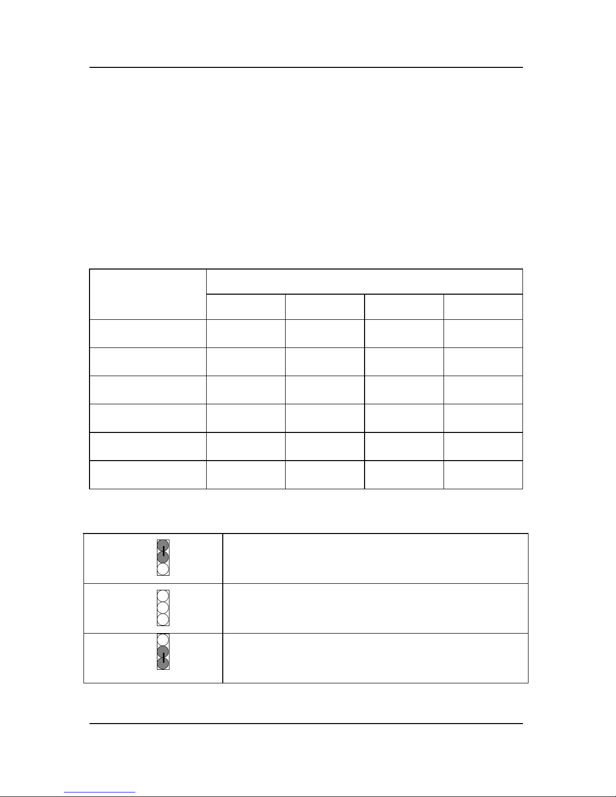
MJP10 (Select the system speed between 66.6MHz and 100MHz)
1-2 Close
System speed is set to 66MHz − system always
run at 66MHz FSB (Front Side Bus).
All Open
System speed is set to 100MHz − system always
run at 100MHz FSB (Front Side Bus).
2-3 Close
Set system speed to Auto
−
system speed
detect automatically (66 / 100MHz FSB).
1
2
1
2
3
1
2
3

6BXD
3
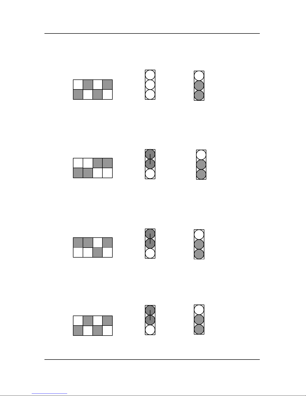
MThere are two ways to set system speed
1. 66MHz (JP10) (1-2 short) or Auto detect (2-3 short)
2. 100MHz (JP10) (1-2-3 open) or Auto detect (2-3 short)
1. Pentium II 300 / 100MHz FSB
CPU2
6BXD
CPU1
PIIX4
82443BX
JP10
2. Pentium II 350 / 100MHz FSB
3. Pentium II 400 / 100MHz FSB
SW
ON
1 2
SW
1 2
ON
Open
Open
JP10
1
2
3
1
2
3
JP10
SW
ON
OFF
432
1
Open
JP10
1
2
3
JP10
1
2
3
2-3
Close
2-3
Close
JP10
1
2
3
100 MHz or Auto
100 MHz or Auto
2-3
Close
JP10
1
2
3
Quick Installation Guide
4
4. Pentium II 450 / 100MHz FSB
5. Pentium II 233 MHz / 66MHz FSB
6. Pentium II 266 / 66MHz FSB
7. Pentium II 300 MHz / 66MHz FSB
SW
ON
1 2
SW
ON
1 2
SW
ON
1 2
SW
ON
1 2
Open
1-2 Short
1-2 Short
1-2 Short
JP10
1
2
3
JP10
1
2
3
JP10
1
2
3
JP10
1
2
3
2-3
Close
JP10
1
2
3
100 MHz or Auto
66 MHz or Auto
2-3
Close
JP10
1
2
3
66 MHz or Auto
2-3
Close
JP10
1
2
3
2-3
Close
JP10
1
2
3
66 MHz or Auto

6BXD
5
8. Pentium II 333 / 66MHz FSB
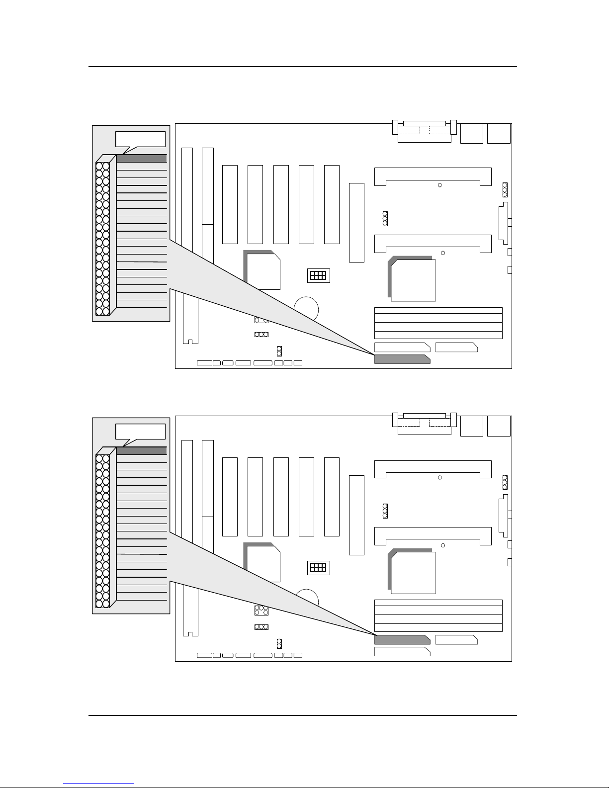
II. Jumper setting :
9. Pentium II 366 / 66MHz FSB
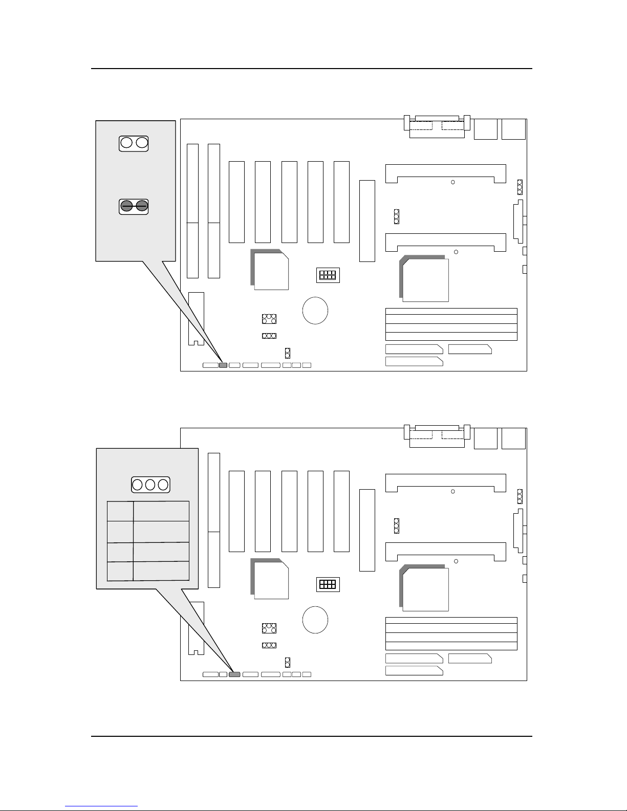
SPK : Speaker Connector
CPU2
6BXD
CPU1
PIIX4
82443BX
JP10
Pin No.
Function
1
2
VCC
NC
3
NC
4
Data
1
SW
ON
1 2
1-2 Short
JP10
1
2
3
2-3
Close
JP10
1
2
3
66 MHz or Auto
SW
ON
1 2
JP10
1
2
3
2-3
Close
JP10
1
2
3
66 MHz or Auto
1-2 Short
Quick Installation Guide
6
RST : Rest Switch
CPU2
6BXD
CPU1
PIIX4
82443BX
JP10
1
Open:
Normal operation
Short:
For Hardware
Reset System
1
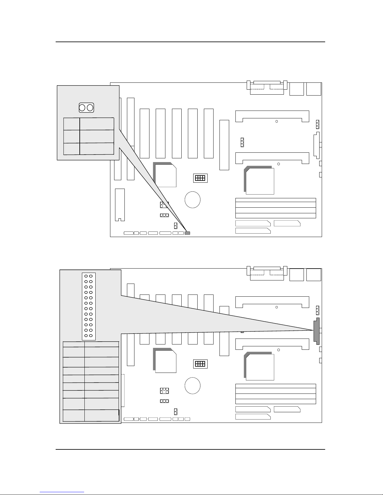
PWR : Power LED
CPU2
6BXD
CPU1
PIIX4
82443BX
JP10
1
Pin No.
Function
1
2
LED anode (+)
LED athode (-)
3
LED athode (-)

6BXD
7
HD : IDE Hard Disk Active LED
CPU2
6BXD
CPU1
PIIX4
82443BX
JP10
1
Pin No.
Function
1
2
LED anode (+)
3
4
LED anode (+)
LED cathode (-)
NC
IR : Infrared Connector
CPU2
6BXD
CPU1
PIIX4
82443BX
JP10
1
GND
IR Data Input
Pin No.
Function
12IR Data Output
3
4
NC
POWER (+)
5

Quick Installation Guide
8
GN : Green Function Switch
CPU2
6BXD
CPU1
PIIX4
82443BX
JP10
1
Open:
Normal operation
Short:
Entering Green Mode
.
1
Soft PWR : Soft Power Connector
CPU2
6BXD
CPU1
PIIX4
82443BX
JP10
1
Open:
Normal operation
1
Short(Two Option):
1.Instant On/Off: Power
On/Off system immediately
2.Delay 4Seconds:
Power Off system Press
over 4 Secs.
6BXD
9
GD : Green Function Active LED Connector
CPU2
686BXD
CPU1
PIIX4
82443BX
JP10
1
Pin No.
Function
1
2
LED anode (+)
LED athode (-)
POWER : Power Connector
CPU2
6BXD
CPU1
PIIX4
82443BX
JP10
1
VCC (+5V)
Power Good
Pin No. Function
4,6,19,20
GND
10
12
18
8
+12V
-12V
-5V
9
14
PS-ON
(Soft ON/OFF)
5V SB
(Stand by +5V)
13,15-17
3,5,7

Quick Installation Guide
10
J1 & J2 : CPU Cooling Fan Power Connector
CPU2
6BXD
CPU1
PIIX4
82443BX
JP10
1
Pin No.
Function
1
2
3
GND
+12V
SENSE
J3 : Keyboard Connector & PS/2 Mouse
CPU2
6BXD
CPU1
PIIX4
82443BX
JP10
Function
2
4
1
3
5
6
Data
NC
VCC(+5)
GND
NC
Clock
Pin No.
PS/2 Mouse
PS/2 MOUSE
PS/2 KEYBOARD
PS/2 Keyboard

6BXD
11
CN1 : USB Port
CPU2
6BXD
CPU1
PIIX4
82443BX
JP10
J5: LPT PORT
CPU2
6BXD
CPU1
PIIX4
82443BX
JP10

Quick Installation Guide
12
JP3: COM A
CPU2
6BXD
CPU1
PIIX4
82443BX
JP10
COM A
JP2: COM B
CPU2
6BXD
CPU1
PIIX4
82443BX
JP10
COM B
6BXD
13
IDE1: For Primary IDE port
CPU2
6BXD
CPU1
PIIX4
82443BX
JP10
1
RED LINE
IDE2: For Secondary IDE port
CPU2
6BXD
CPU1
PIIX4
82443BX
JP10
1
RED LINE

Quick Installation Guide
14
FLOPPY : FLOPPY PORT
CPU2
6BXD
CPU1
PIIX4
82443BX
JP10
1
RED LINE
JP1 : Keyboard Power On
CPU2
6BXD
CPU1
PIIX4
82443BX
JP10
2,3 Short :
Disable Keyboard Power
On.
1,2 Short :
Enable Keyboard Power
On.
1
1
JP1

6BXD
15
JP12: Wake on Lan
CPU2
6BXD
CPU1
PIIX4
82443BX
JP10
Pin No.
Function
1
2
3
GND
Signal
+5V
1
J12: System After Ac Back
CPU2
6BXD
CPU1
PIIX4
82443BX
JP10
1
Open: Soft Off
Short: Full on/Soft Off
Pin No.
Function
1
2
GND
Signal
Quick Installation Guide
16
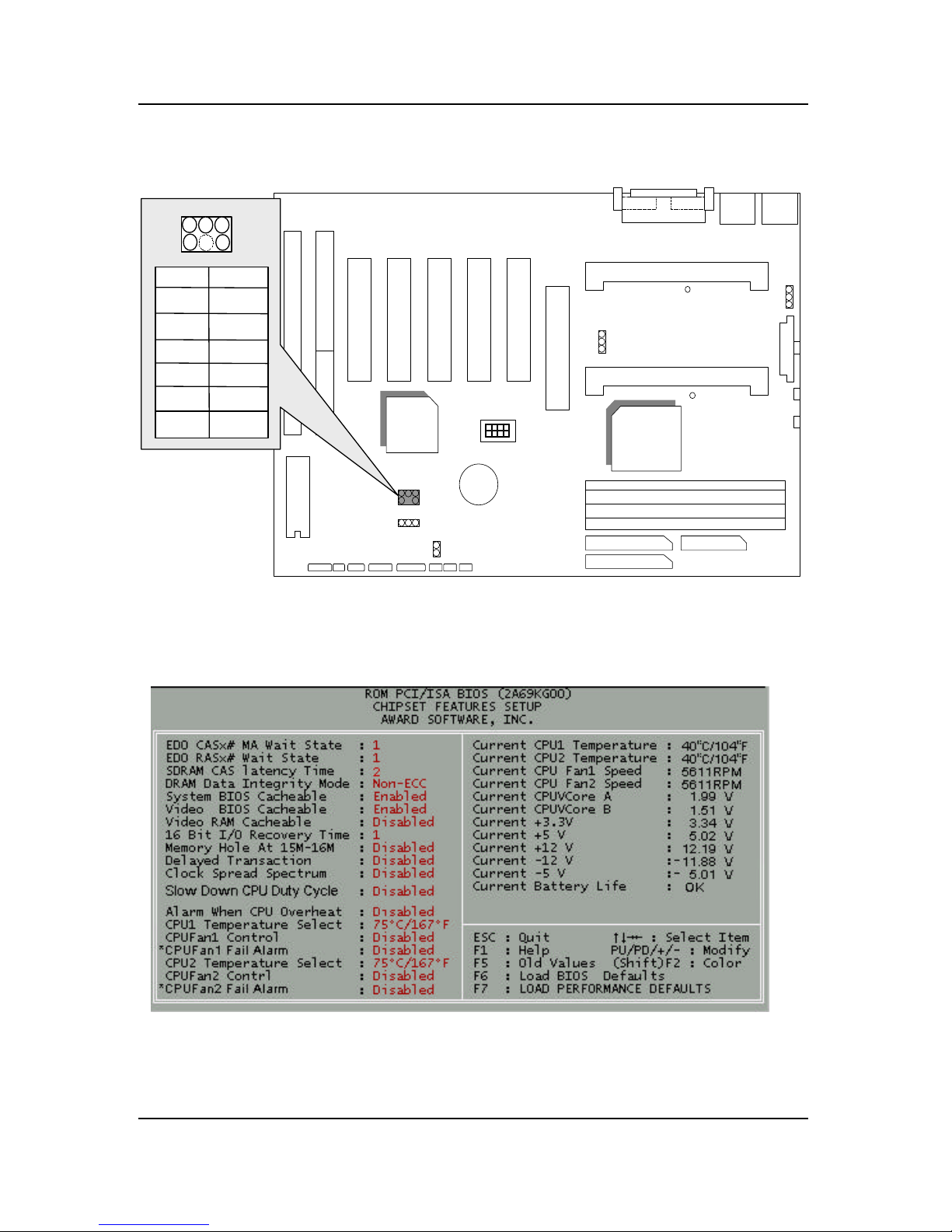
JP11: For PCI Audio / Sound Card use only
CPU2
6BXD
CPU1
PIIX4
82443BX
JP10
6
5
2
1
Pin No. Function
1
2
GND
Signal
3
NC
4
Signal
5
GND
6
Signal
III. Top Performance Test Setting:
Users have to modify the value for each item in chipset features as follow
for top performance setting.
**
Each value of items as above depends on your hardware configuration :
CPU , SDRAM , Cards , etc.
Please modify each value of items If your system does not work

6BXD
17
properly .

6BXD
1
TABLE OF CONTENTS
1. INTRODUCTION
1.1. PREFACE...................................................................................1-1
1.2. KEY FEATURES.........................................................................1-1
1.3. PERFORMANCE LIST................................................................1-2
1.4. BLOCK DIAGRAM ......................................................................1-3
1.5. INTRODUCE THE Pentium II Processor...................................1-4
1.6. WHAT IS AGP?...........................................................................1-6
2. SPECIFICATION
2.1. HARDWARE...............................................................................2-1
2.2. SOFTWARE ...............................................................................2-2
2.3. ENVIRONMENT..........................................................................2-2
3. HARDWARE INSTALLATION
3.1. UNPACKING...............................................................................3-1
3.2. MAINBOARD LAYOUT................................................................3-2
3.3. QUICK REFERENCE FOR JUMPERS & CONNECTORS............3-2
3.4. DRAM INSTALLATION................................................................3-5
3.5. CPU SPEED SETUP...................................................................3-6
3.6. CMOS RTC & ISA CFG CMOS SRAM.........................................3-7
3.7. SPEAKER CONNECTOR INSTALLATION ..................................3-7
3.8. HARDWARE RESET SWITCH CONNECTOR INSTALLATION ...3-7
3.9. POWER LED CONNECTOR INSTALLATION..............................3-7
3.10. IDE & ATAPI DEVICE INSTALLATION......................................3-8
3.12. PERIPHERAL DEVICE INSTALLATION ....................................3-8
3.13. KEYBOARD & PS/2 MOUSE INSTALLATION...........................3-8

Table Of Contents
2
3.14. KEYBOARD SETTING FUNCTION...........................................3-8
4. BIOS CONFIGURATION
4.1. ENTERING SETUP.....................................................................4-1
4.2. CONTROL KEYS........................................................................4-1
4.3. GETTING HELP..........................................................................4-2
4.3.1.Main Menu.........................................................................4-2
4.3.2.Status Page Setup Menu / Option Page Setup Menu..........4-2
4.4. THE MAIN MENU........................................................................4-2
4.5. STANDARD CMOS SETUP MENU..............................................4-4
4.6. BIOS FEATURES SETUP...........................................................4-8
4.7. CHIPSET FEATURES SETUP.....................................................4-13
4.8. POWER MANAGEMENT SETUP................................................4-19
4.9. PNP/PCI CONFIGURATION .......................................................4-22
4.10. LOAD BIOS DEFAULTS............................................................4-24
4.11. LOAD PERFORMANCE DEFAULTS .........................................4-25
4.12. INTEGRATED PERIPHERALS..................................................4-26
4.13. USER PASSWORD...................................................................4-32
4.14. IDE HDD AUTO DETECTION....................................................4-33
4.15. SAVE & EXIT SETUP ...............................................................4-34
4.16. EXIT WITHOUT SAVING..........................................................4-35

6BXD
1-1
1. INTRODUCTION
1.1. PREFACE
Welcome to use the 6BXD motherboard. The motherboard is a Dual
Pentium II Processor based PC / AT compatible system with AGP / PCI /
ISA Bus, and has been designed to be the fastest PC / AT system. There are
some new features allow you to operate the system with just the performance
you want.
This manual also explains how to install the motherboard for operation, and
how to set up your CMOS CONFIGURATION with BIOS SETUP program.
1.2. KEY FEATURES
q Intel Dual Pentium
II Processor based PC / AT compatible mainboard.
q Dual Slot 1 on board supports dual Pentium
II processor running at 200-
633MHz.
q Intel 440BX chipset, Support AGP / SDRAM / Ultra DMA/33 IDE / ACPI
features.
q Support CPU FAN Failure / Overheat Alarm & auto slow down CPU
speed.
q Support PS/2 mouse & Keyboard Wake Up function.
q Support Intel LDCM
Network Manageability.
q Support PCI Audio & Wake on Lan function.
q Supports 4xDIMMs using 3.3V EDO or SDRAM DIMM module.
q Supports 8 MB - 1 GB EDO / 1GB SDRAM memory on board.
q Supports ECC or Non-ECC type DRAM module.
q 1xAGP slot, 5xPCI Bus slots, 2xISA Bus slots.
q Supports 2 channels Ultra DMA/33 IDE ports for 4 IDE Devices.
q Supports 2xCOM (16550), 1xLPT (EPP / ECP), 1x1.44MB Floppy port.
q Supports 2xUSB ports, 1xPS/2 Mouse & 1xPS/2 Keyboard ports.
q Licensed AWARD BIOS, 2M bits FLASH RAM.

Introduction
1-2
q ATX form factor, Double stack I/O connector, 4 layers PCB.
1.3. PERFORMANCE LIST
The following performance data list is the testing results of some popular
benchmark testing programs.
These data are just referred by users, and there is no responsibility for
different testing data values gotten by users. (The different Hardware &
Software configuration will result in different benchmark testing results.)
• CPU
Pentium II processor
• DRAM 128 MB SDRAM (NEC D4564841G5-A10-9JF)
• CACHE SIZE 512 KB included in CPU
• DISPLAY GA-601 4MB AGP VGA
• STORAGE Onboard IDE port (IBM DHEA 38451)
• O.S. Windows NT™ 4.0
• DRIVER Display Driver at 1024 x 768 x 256 colors x 75Hz
Triones Bus Master IDE Driver 3.60K
Intel Pentium II
Processor
333MHz (66 × 5) 350MHz (100 × 3.5)
Winbench98
CPU mark32
862 944
FPU Winmark
1720 1800
Business Disk
1900 1940
Hi-End Disk
4570 4690
Business Graphics
185 206
Hi-End Graphics
206 230
Winstone98
Business
33 35.1
Hi-End
38.6 39.3
6BXD
1-3
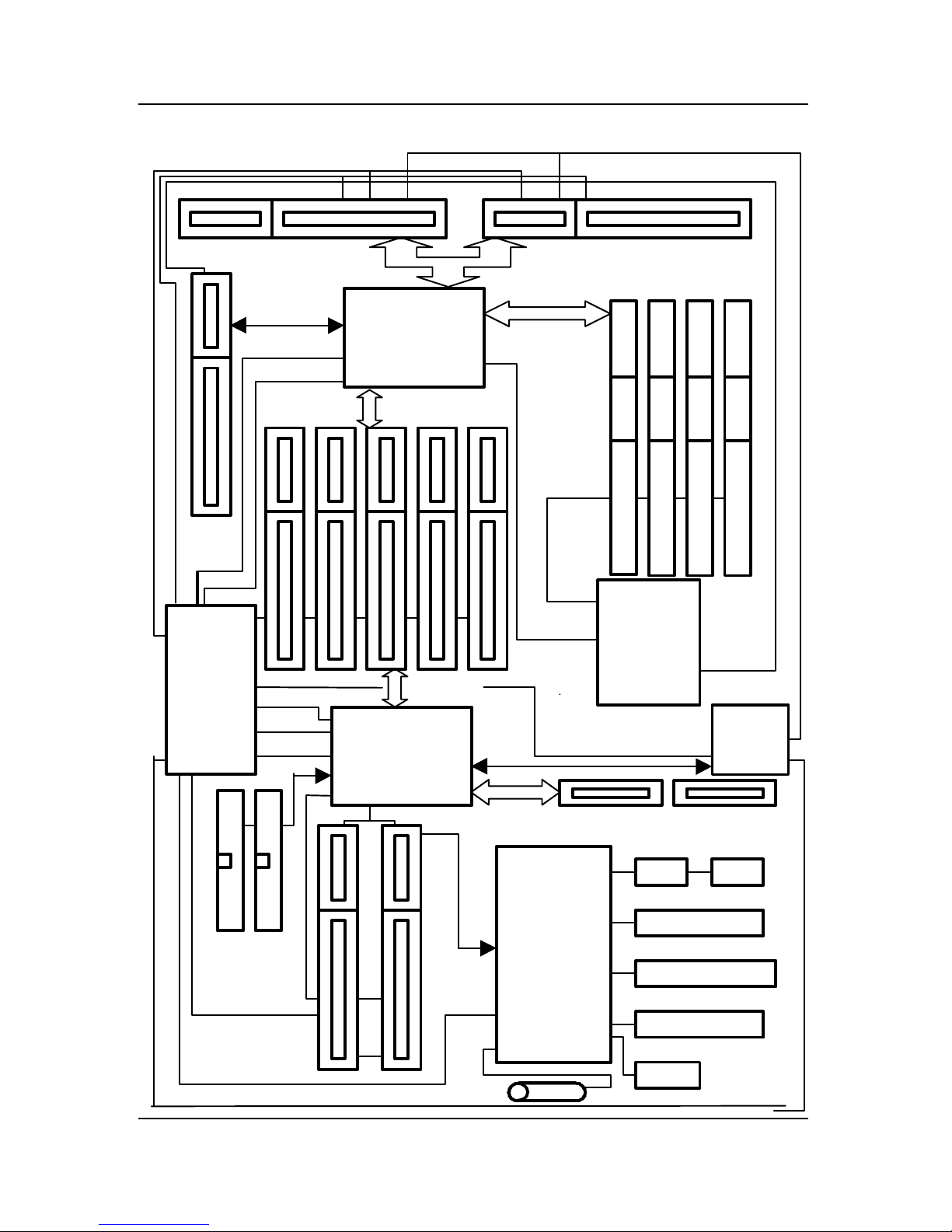
66/100MHz
8MHz
Floppy Port
3.3VEDO/SDRAM
1.4. BLOCK DIAGRAM
14.318MHz
IDE Bus
ISA Bus
AGP
SLOT
SLOT 1 (CPU 2)
66MHz
PCI Bus
PCI Bus
66/100MHz
LPT Port
USB #2
PS/2 Keyboard
COM Ports
USB #1
DRAM
PS/2 Mouse
USB Bus
SLOT 1 (CPU 1)
AGP Bus
Host Bus
PAC
82443BX
CHIPSET
I/
O
83977TF
32.768KHz
48MHz
CLO
CK
G
EN
9148BF-10
33MHz
14.318MHz
33MHz
14.318MHz
CLOCK
GE
N
9179BF-01
48MHz
I/O
APIC
PIIX4
CHIPSET
14.318MHz
33MHz
66/100MHz
66/100MHz
 Loading...