

Page 1

R-22-01-081015
686LX3
USER'S MANUAL
1. System power on by PS/2 Mouse: First, enable this function
in CMOS Setup, then you can power on the system by double
clicking the right or left button of your PS/2 Mouse.(Optional)
2. System power on by Keyboard: If your ATX power supply
supports larger than 100~300 mA 5V Stand-By current, you
can power on your system by entering password from the
keyboard after setting the “Keyboard power on” password in
CMOS Setup.
3. Supports 3 steps ACPI LED
4. WAKE-UP ON LAN. (The ATX power supply supports larger
than 720 mA 5V Stand-By current)
M J13.JP12.J6 Jumpers for PCB 2.0/2.2 use, please reference
P16¡BP17
Pentium II Processor MAINBOARD
Page 2

Table of Contents
2
REV. 2.2 First Edition
Page 3

686LX3
1
The author assumes no responsibility for any errors or omissions that may
appear in this document nor does it make a commitment to update the
information contained herein.
Third-party brands and names are the property of their respective owners.
Sound Blaster is a registered trademark of Creative Technology Ltd in the
United States and certain other countries. Sound Blaster-LINK and SB-LINK
are trademarks of Creative Technology Ltd.
Page 4

Quick Installation Guide
2
Oct 15, 1998 Taipei, Taiwan
I. Quick Installation Guide:
CPU SPEED SETUP
The default system bus speed is set to 66MHz. The user can change the DIP
SWITCH (SW) selection to set up the CPU speed for 200 - 366MHz processor.
The CPU speed MUST match with the frequency RATIO and external
clock frequency. It will cause system hanging up if the frequency RATIO
and the external clock frequency are higher than that of CPU.
DIP SWITCH (SW)
FREQ. RATIO
SW1 SW2 SW3 SW4
X 3
ON OFF ON ON
X 3.5
OFF OFF ON ON
X 4
ON ON OFF ON
X 4.5
OFF ON OFF ON
X 5
ON OFF OFF ON
X 5.5
OFF OFF OFF ON
MJP2, JP3, JP4 (Select the system speed¡Ð66 / 75 / 83 / 100MHz )
Main Clock JP4 JP3 JP2
66 MHz
1-2 1-2 1-2
75 MHz
1-2 2-3 1-2
83 MHz
2-3 1-2 2-3
100 MHz
1-2 2-3 2-3
«Note: We don’ t recommend you to setup your system speed to 75, 83
or 100MHz because these frequencies are not the standard
specifications for CPU, Chipset and most of the peripherals.
Whether your system can run under 75, 83 or 100MHz properly will
depend on your hardware configurations: CPU, SDRAM, Cards,
etc.
Page 5
686LX3
3
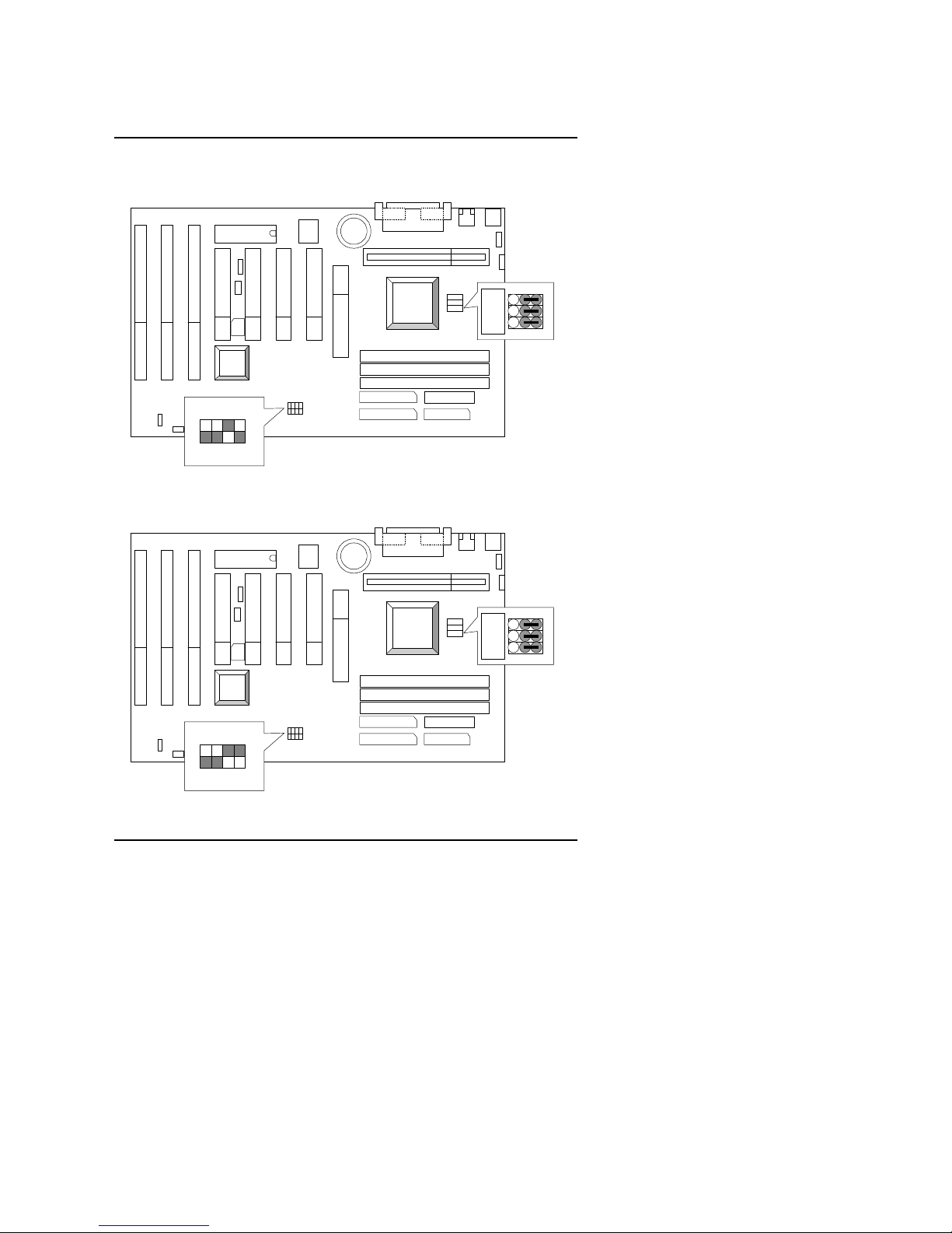
1. Pentium II 200 MHz
686LX3
PIIX4
INTEL
440LX
ON
4 3 2 1
JP2
JP3
JP4
3 2 1
2. Pentium II 233 MHz
686LX3
PIIX4
INTEL
440LX
ON
4 3 2 1
JP2
JP3
JP4
3 2 1
Page 6

Quick Installation Guide
4
3. Pentium II 266 MHz
686LX3
PIIX4
INTEL
440LX
ON
4 3 2 1
JP2
JP3
JP4
3 2 1
4. Pentium II 300 MHz
686LX3
PIIX4
INTEL
440LX
ON
4 3 2 1
JP2
JP3
JP4
3 2 1
Page 7

686LX3
5
5. Pentium II 333 MHz
686LX3
PIIX4
INTEL
440LX
ON
4 3 2 1
JP2
JP3
JP4
3 2 1
6. Pentium II 366 MHz
686LX3
PIIX4
INTEL
440LX
ON
4 3 2 1
JP2
JP3
JP4
3 2 1
Page 8

Quick Installation Guide
6
II. Jumper setting :
PWR : Power LED Connector
686LX3
PIIX4
INTEL
440LX
Pin No Functioin
1 LED (+)
2 LED (-)
3 LED (-)
1
SPK : Speaker Connector
686LX3
PIIX4
INTEL
440LX
Pin No Function
1 VCC(+)
2 NC
3 NC
4 Data(-)
1
+
–
Page 9

686LX3
7
RST : Reset Switch
686LX3
PIIX4
INTEL
440LX
Open: Normal
Close:
Reset System
GN : Green Function Switch
686LX3
PIIX4
INTEL
440LX
Close:
Enter Green Mode
Open:
Normal
Page 10

Quick Installation Guide
8
GD : Green LED
686LX3
PIIX4
INTEL
440LX
Pin No Function
1 LED (+)
2 LED (-)
1
+
HD : IDE Hard Disk Active LED
686LX3
PIIX4
INTEL
440LX
Pin No Function
1 LED (+)
2 LED (-)
1
Page 11

686LX3
9
Soft PWR : Soft Power Connector
686LX3
PIIX4
INTEL
440LX
Open:
Normal
operation
Short:
Power On/Off
IR : Infrared Connector (Optional)
686LX3
PIIX4
INTEL
440LX
1
2
3
4
5
IR Data Output
GND
IR Data Input
NC
POWER (+)
Function
Pin No
Page 12

Quick Installation Guide
10
POWER : Power Connector
686LX3
PIIX4
INTEL
440LX
1
Power Good
Pin No.
3,5,7,13,
15-17
4,6,19,20
10
12
18
8
9
14
Function
GND
VCC(+5V)
+12V
-12V
-5V
5V SB
PS-ON
PS/2 Mouse / Keyboard Connector
686LX3
PIIX4
INTEL
440LX
Pin No Function
1
2
3
4
5 Clock.
Data
NC
VCC (+5V)
GND
6 NC
PS/2 Keyboard
PS/2 Mouse
Page 13

686LX3
11
J1 : CPU Cooling Fan Power Connector
686LX3
PIIX4
INTEL
440LX
Pin No Function
1 GND
2 +12V
3 SENSE
1
IDE1: For Primary IDE port
686LX3
PIIX4
INTEL
440LX
1
RED LINE
1 1
1
IDE1
IDE2
FLOPPY
Page 14

Quick Installation Guide
12
IDE2: For Secondary IDE port
686LX3
PIIX4
INTEL
440LX
1
RED LINE
1 1
1
IDE1
IDE2
FLOPPY
J7 : FLOPPY PORT
686LX3
PIIX4
INTEL
440LX
1 1
1
IDE1
IDE2
FLOPPY
1
RED LINE
Page 15

686LX3
13
LPT PORT / COM A / COM B
686LX3
PIIX4
INTEL
440LX
COM B
LPT PORT
COM A
COMA COMB
LPT PORT
JP1 : Keyboard Power On Selection
686LX3
PIIX4
INTEL
440LX
Keyboard Power On
Default: Disable
1
2
3
1-2
2-3
Enable
Disable
Page 16

Quick Installation Guide
14
CN1: USB Port
686LX3
PIIX4
INTEL
440LX
Pin No. Function
1
2
3
4
5
6
7
8
USB D0USB D0+
GND
USB V0
GND
USB V1
USB D1USB D1+
JP10: Wake on LAN
686LX3
PIIX4
INTEL
440LX
JP10
1
Pin
No
1
2
3
Function
+5V SB
GND
Signal
Page 17

686LX3
15
JP9 :SB-Link (Creative PCI Sound Card Support)
686LX3
PIIX4
INTEL
440LX
JP912
456
SB-LINK
Pin
No
1
2
3
Function
Signal
GND
NC
4
5
Signal
GND
Signal
6
BAT1:For Battery
Danger of explosion if battery is incorrectly replaced.
Replace only with the same or equivalent type recommended by the manufacturer.
Dispose of used batteries according to the manufacturer’s instructions.
686LX3
PIIX4
INTEL
440LX
Page 18

Quick Installation Guide
16
J13: ATX Power Control Selection (PCB Only ver:2.0 use)
686LX3
PIIX4
INTEL
440LX
J13
Open: Soft Off
Close: Full On
JP12:CLEAR CMOS Function (PCB Only ver:2.2 use)
686LX3
PIIX4
INTEL
440LX
1
1-2 :CLEAR CMOS
2-3 :NORMAL
Default :2-3 Short
Page 19

686LX3
17
J6:RING POWER ON ( PCB Only ver:2.2 use)
686LX3
PIIX4
INTEL
440LX
1
PIN
NO
Function
1
2
Signal
GND
III. Top Performance Test Setting:
Users have to modify the value for each item in chipset features as follow
for top performance setting.
Page 20

 Loading...