

Page 1

© Copyright September, 2005
This publication, including all photographs, illustrations and software, is
protected under international copyright laws, with all rights reserved. Neither
this manual, nor any of the material contained herein, may be reproduced
without written consent of Giga-byte Technology Co., Ltd.
The information in this document is subject to change without notice. The
manufacturer makes no representations or warranties with respe ct to
the contents hereof and specifically disclaims any implied warranties of
merchantability or fitness for any particular purpose. The manufacturer
reserves the right to revise this publication and to make changes from time to
time in the content hereof without obligation of the manufacturer to notify any
person of such revision or changes.
Trademark Recognition
Gigabyte and Giga-byte are trademarks of Giga-byte Technology Co., Ltd.
Microsoft and Windows XP are trademarks of Microsoft Corporation.
All other product names used in this manual are the properties of their
respective owners and are acknowledged.
Page 2
I
FCC Warning
This equipment has been tested and found to comply with the limits for a Class B digital
device pursuant to Part 15 of the FCC Rules. These limits are designed to provide
reasonable protection against harmful interference when the equipment is operated in
a commercial environment.
This equipment generates, uses, and can radiate radio frequency energy and, if not
installed and used in accordance with the instruction manual, may cause harmful
interference to radio communications. Operation of this equipment in a residential area
is likely to cause harmful interference in which case the user will be required to correct
the interference at his own expense.
Changes or modifications not expressly approved by the parties responsible for
compliance could void the user’s authority to operate the equipment.
Important Safety Information
We recommend that you read this section carefully before using the HA91. These
safety and usage instructions will ensure that you enjoy many years safe use of the
HA91. Keep this manual for future reference.
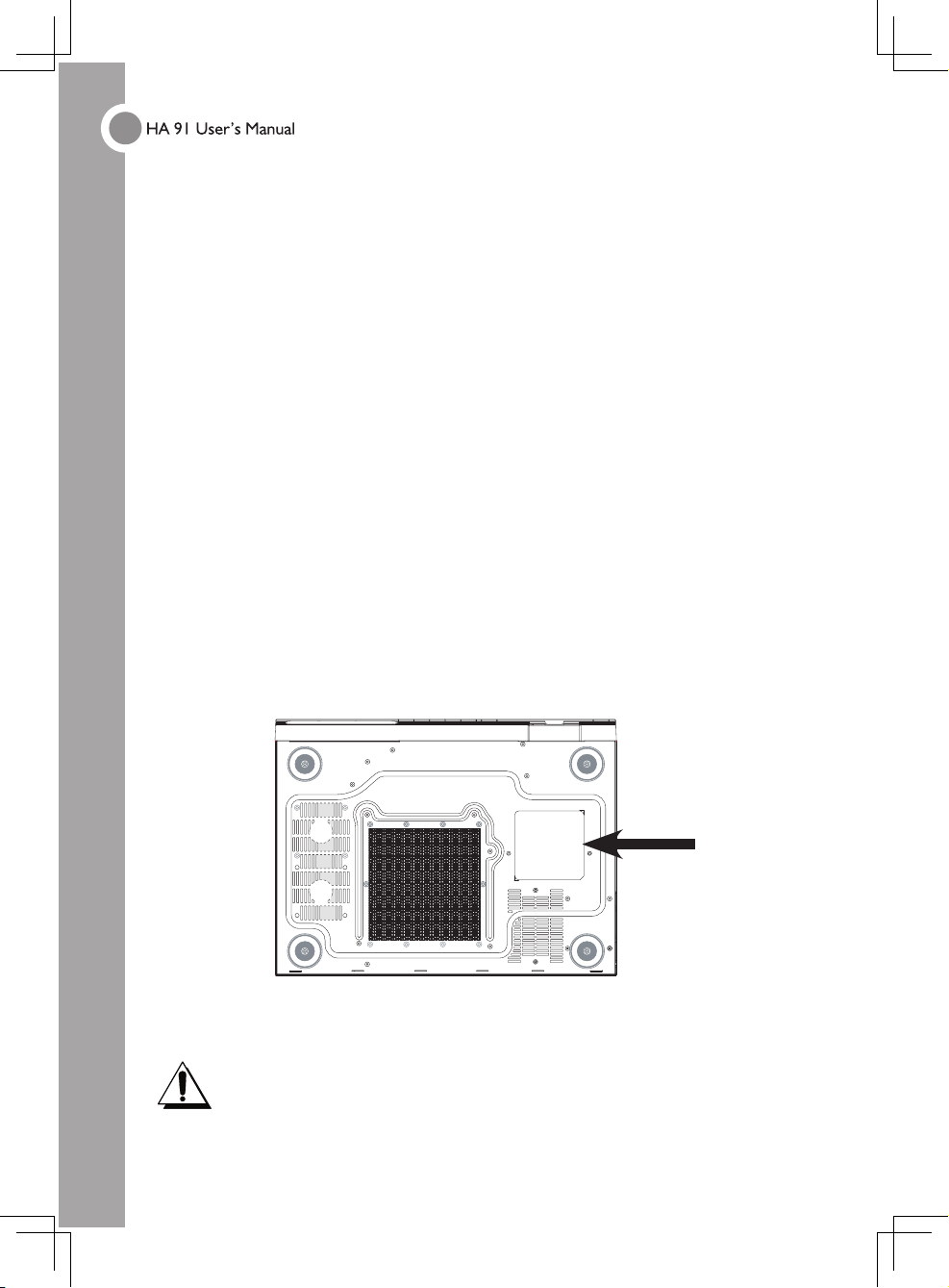
Warning Symbols on the HA91 Case
Be sure to read the power rating label on the bottom of the HA91 before operation.
Caution:
Before connecting power to the HA91, make sure the power source is within
the range of AC 100~240V, 50~60 Hz.
Do not attempt to service the HA91 yourself. If the unit gets wet or you think it
is damaged, have the unit serviced. Do not open the unit case for any reason.
RATING
LABEL
Page 3
II
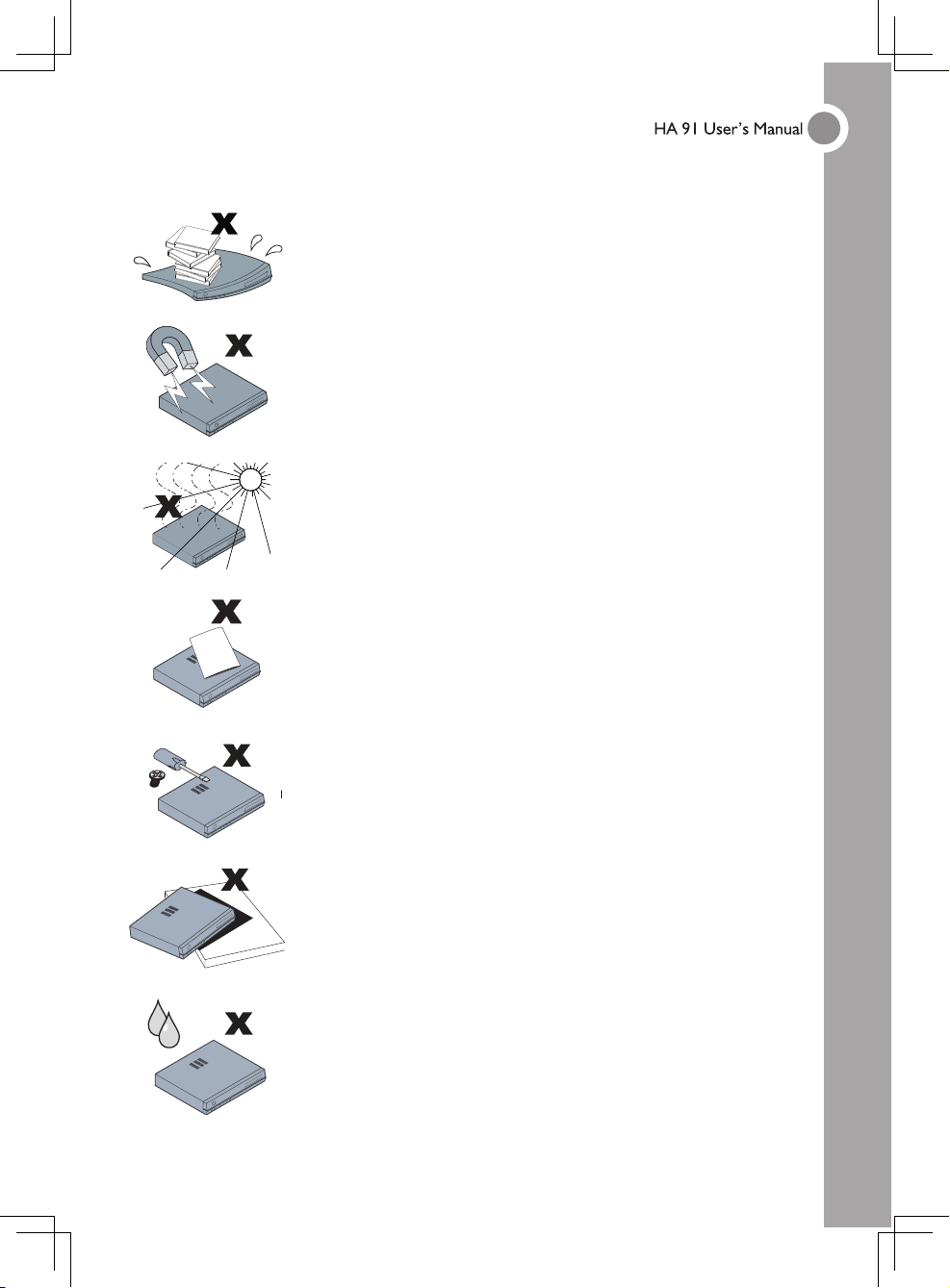
General Safety Information
• Do not place heavy objects such as books or bags on the unit.
• Avoid placing objects with strong magnets built in too close to
the unit. If you suspect stereo speakers may interfere with the
unit, try moving the speakers away from the unit.
• Avoid using the system in direct sunlight, or near a heating
device.
• To prevent the unit from overheating, do not cover the air
ventilation openings on the top, sides, or the rear.
• Do not open the unit case. Do not attempt to service the HA91
yourself. For servicing, contact qualified service personnel.
• Do not place the unit on an unstable surface, cart, or stand.
• Avoid exposing the HA91 to moisture or excessive humidity.
• Follow all warnings and cautions in this manual and on the unit case.
Page 4
III
Power Safety
• Only use the supplied power cord.
• Do not place anything on the power cord. Place the power cord where it will not be in
the way of foot traffic.
• Remove the batteries from the remote control when storing or not in use for a
prolonged period.
• Before connecting power to the HA91, make sure the power source is within the range
of AC 100~240V, 50~60 Hz.
HDD Partition:
It is strongly recommend not to partitioning the hard disk.
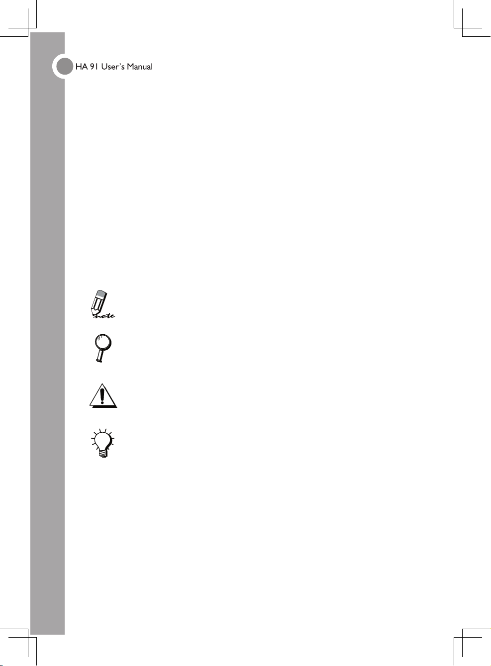
Manual Styles
The following styles are used in this manual to alert you to important information.
Note Style
Provides additional information on the topic at hand.
Provides information that should not be overlooked.
Alerts you to situations that may damage the unit or cause personal
injury.
Provides helpful information on the topic at hand.
Page 5
IV
CONTENTS
Chapter One Getting Started
1.1 Packing Checklist .................................................................................. 1
1.2 Views of HA91 ........................................................................................ 2
1.3 Remote Control Functions ................................................................... 9
1.4 Keyboard Functions .............................................................................. 11
1.5 Remote Control and Keyboard Operating Range ........................... 13
Chapter Two Making Connections
2.1 Connecting Input Devices ...................................................................14
2.2 Connecting a Monitor ...........................................................................15
2.3 Connecting Speaker or an Amplifier ...................................................
16
2.4 Setting up a 5.1 Audio Environment ....................................................17
2.5 Connecting a TV Antenna ....................................................................18
2.6 Connecting to a LAN ............................................................................19
2.7 Connecting the Power Cable .............................................................. 20
Appendix A Specification ...........................................................................
21
CONTENTS
Page 6
1
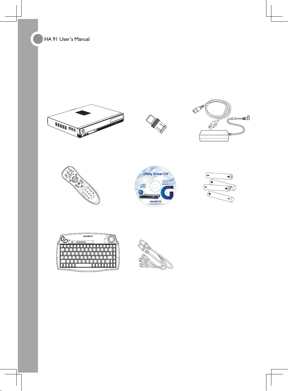
1.1 Packing Checklist
Carefully unpack the HA91 and check that besides this User Manual the following items
are included:
Contact your dealer immediately if any items are missing, appear damaged, or if the
unit does not work.
CHAPTER ONE
HA91 Power cord & Adapter
Remote control Recovery CD
RF keyboard
Two AA for RF
keyboard &
two AA for remote
controller (MCE)
Cable
TV quick connector
For NTSC model only
Page 7
2
CHAPTER ONE
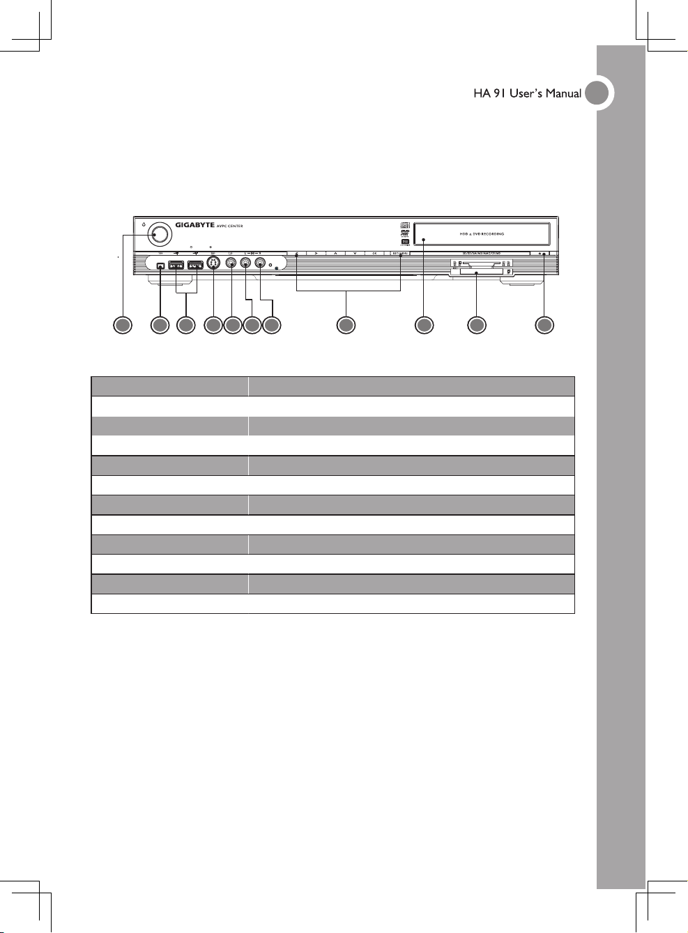
1.2 Features at a Glance
►Front View
Item Description
1. Power Push the Power Button to turn the HA91 on.
2. IEEE 1394 (4-pin) Connect IEEE1394-enabled devices.
3. USB 2.0 Connect USB-enabled devices.
4. S-Video In Connector for S-Video in.
5. Composite Video In Connector for Video in.
6. Composite Audio In (L) Connector for Audio in (Left Channel).
7. Composite Audio In (R) Connector for Audio in (Right Channel).
8. VFD VFD (Vacuum Fluorescent Display).
9. DVD Super Multi DVD-Multi Recoder.
10. Card Reader 6-in-1 card reader.
11. DVD Eject
Push to enject a disc from the DVD drive.
1 2 4 5 6 7 8 9 103
11
Page 8
3
CHAPTER ONE
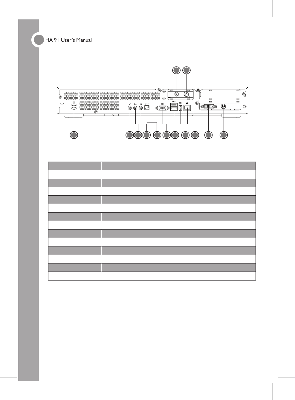
►Rear View
Item Description
1. Power Connect the power cord DC Jack here.
2. MIC-In Connect a microphone here.
3. LINE-Out Connect to speakers or an amplifier.
4. LINE-In Stereo audio input port.
5. SPDIF Digital audio output connector.
6. RGB Out Connected to flat screen.
7. USB (x2) Connect USB-enabled devices here.
8. IEEE1394 (6-pin) Connect IEEE1394-enabled devices here.
9. LAN Connect to an RJ-45 connector (Ethernet cable).
10. DVI Port Connect to digital monitor.
11. S-Video Port Connect to a television or display device with S-Video input.
12. CATV
Cable-TV input.
13. Video/ Audio in Connector for Video/Audio in.
1 2 5 7
12
13
43 6
8
9
10
11
Page 9

4
CHAPTER ONE
►VFD (Vacuum Fluorescent Display) Messages
The LED display on the front of the HA91 displays status information. As well as disc
information, the following messages display in the LED display:
Item Description
1 Displays the volume level.
2 Displays the volume level.
3 Displays the current mode.
4 Display time information, media play time, and mode status.
3 4
1 2
Not used.
Page 10

5
►Normal Windows Mode (Media Center Applications are not run) / Sleep Mode
Status:
1. The system is turn on in normal Windows mode. Media Center applications are not
run.
2. System is sleeping.
Description:
1. Time is shown. The clock control by VFD MCU.
2. Volumes of audio in left and right are shown.
3. Run Disk is stop.
►Start to run Media Center Applications / On Meida Center Home Frame
Status:
1. Press “Start” button to run Media Center applications and the system is in Media
Center Home frame.
2. User can use ▲ and ▼ to choose the wanted multi-media in MCE.
Description:
1. No display information shown.
2. Run Disk is stop.
CHAPTER ONE
Page 11

6
►My Video Mode
Status:
When “My Videos” is selected, the screen is on video frame and stop mode.
Description:
1. “VIDEO” is shown
2. Run Disk is stop till the media is played.
►My Picture Mode
Status:
On “My Pictures” frame and stop mode.
Description:
1. “PICTURE” is shown.
2. Run Disk is stop.
* Run Disk can be rotating when the previous selected media is keep playing.
CHAPTER ONE
Page 12

7
►My Music Mode
Status:
On “My Music” frame and stop mode.
Description:
1. “MUSIC” is shown.
2. Run Disk is stop till the media is played.
►TV Mode
Status: On “My TV” frame and stop mode.
Description:
1. “TV” is shown.
2. Run Disk is stop till the media is played.
Status: On TV frame and go to live TV.
Description:
1. It will show the channel number once press the button of “CH_PG”.
2. Run Disk is running.
CHAPTER ONE
Page 13

8
Status: On TV frame and go to record TV.
Description:
1. “REC SHOW” is shown.
►Music / DVD / Video / Play Mode
Status: On music, DVD, video frame and play mode
Description:
1. When playing the music, it will show the track time on Music frame or Home frame.
2. Run Disk is running.
3. If you go to “My Pictures” on picture frame, then “PICTURE” is shown on the
display.
►CD Burning Progress
Status: CD burning progress….
Description:
1. When the dot-block is full, means the CD burring progress is complete.
2. This example shown is 100% in the last 2 dot-block.
CHAPTER ONE
Page 14

9
1.3 Remote Control Functions
Item Function
Power on/off
Stop
Recording Button
Play
Pause
Fast Rewind
Fast Forward
Previous Track
Next Track
Back
More Information
Direction Keys: Up/ Down
Enter Key: OK
Direction Keys: Left/ Right
Next Channel (TV)
Previous Channel (TV)
“START” Menu
Mute
VOL
Volume Up
VOL
Volume Down
CHAPTER ONE
ENTERCLEAR
GUIDE LIVE TV
DVD
MENU
RECORDED
TV
MUTE
VOL
CH
PG
START
BACK MORE
SKIPREPLAY
FWDREW
R
E
C
O
R
D
S
T
O
P
P
A
U
S
E
Page 15

10
►Inserting the Remote Control Batteries
The battery compartment is on the underside of the remote control. Remove the
batteries when not using the HA91 for a longer period.
1. Only use AA batteries.
2. Dispose of used batteries according to local ordinance regulations.
3. Remove the batteries when not using the HA91 for prolonged periods.
CHAPTER ONE
1. Pull the latch upward and open the battery
compartment cover.
2. Insert 2 AA batteries taking note of the correct polarity
(+/-).
3. Close the cover.
Page 16

11
1.4 Keyboard Function
►Using the trackball and buttons
The trackball and buttons have the same functions as a PC mouse. Roll the trackball
to move the cursor on the screen, use the left and right buttons as you do a standard
mouse.
►Shortcut Buttons
In addition to the normal keys found on standard keyboards, the HA91 keyboard
features a number of shortcut buttons, whose functions are outlined below.
Button Function
Power Power button.
AV
MCE/PCM start up.
PC
Back to PC screen.
IE Internet.
E-MAIL
Shortcut button to your e-mail manager.
Left Button
Right Button Shortcut Buttons Trackball
CHAPTER ONE
Page 17

12
►Inserting the Keyboard Batteries
The battery compartment is on the underside of the keyboard. Remove the batteries
when not using the HA91 for a longer period.
1. Lift as shown to remove the cover.
2. Insert two AA batteries taking note of the
correct polarity (+/-).
3. Replace the cover.
1. Only use AA batteries.
2. Dispose of used batteries according to local ordinance regulations.
3. Remove the batteries when not using the HA91 for prolonged periods.
CHAPTER ONE
Page 18

13
►Set Up for Linkage
1. Remove the cover and check if the batteries have been installed. (You can follow
instructions on P.12 Inserting the Keyboard Batteries).
2. Press connect button on the front panel. After pressing the button, its indicator will
light (slowly) and waiting for the match signal from RF Keyboard.
3. Then press this learning button on RF Keyboard to let receiver recognize signal. As
soon as the linkage is completed, the indicator turns to quick flash.
1.5 Remote Control and Keyboard Operating
Range
The remote control uses infrared transmission to control the HA91. It is not necessary
to point the remote directly at the HA91. Provided you are facing the HA91, the remote
will function well within a radius of about 3 meters (10 feet) and 30 degrees above or
below the HA91 level. If the HA91 does not respond to the remote control, move a little
closer or replace the batteries.
CHAPTER ONE
Press this button
LED is bricking slowly
Press this button
Page 19

14
CHAPTER TWO
2.1 Connecting Input Devices
Many of the connectors on the HA91 support the connection of more than one kind of
device. For example, USB printers, keyboards, or scanners can be connected to any of
the USB ports.
USB
Compliant device
1394
Compliant device
Memory Cards
MIC-In
Audio-Out
Monitor
SPDIF
LAN
LCD TV
USB
Compliant device
1394
Compliant
device
TV
Page 20

15
CHAPTER TWO
2.2 Connecting a Monitor/ Flat Display
Check the connectors on your monitor; many monitors have both a VGA (analog)
connector and a DVD-I (digital) connector. If the monitor has both connectors, use the
DVI-I connection as digital provides a better quality signal.
The following directions refer to connecting a VGA:
1. Connect the cable to the VGA connector on the HA91. Tighten the securing screws.
2. Connect the other end of the cable to corresponding connector on the monitor and
tighten the securing screws.
Page 21

16
2.3 Connecting Speakers or an Amplifier
There are many options for connecting amplifiers using both analog and digital
connections.
Analog connections are made using the line-out connector. Digital connections are
made using the SPDIF connector.
SPDIF (Sony/Philips Digital InterFace) is an interface for transferring digital
audio between devices such as CD and DVD players and amplifiers. Use
this connection if available on your amplifier.
CHAPTER TWO
Page 22

17
2.4 Setting up a 5.1 Audio Environment
The 5.1 channel audio environment is a digital audio playback system for
home theater. It includes five channels (left, right, center, rear/surround left
and right) plus a subwoofer channel.
CHAPTER TWO
Page 23

18
2.5 Connecting a TV Antenna
Before you can watch TV you must connect an antenna or a CATV cable to the HA91.
1. Connect your VHF/UHF (antenna) or CATV cable to the ANT connector on the HA91.
2. Connect the other end of the cable to the antenna or CATV socket.
After connecting the antenna you need to scan for channels.
For convenient connection and disconnection use the provided TV quick
connector cable.
CHAPTER TWO
Page 24

19
2.6 Connecting to a LAN
To go online and send or receive email you must have an Internet connection.
If you have an existing ADSL account, connect the RJ-45 cable from your ADSL to the
LAN connector on the HA91.
CHAPTER TWO
Page 25

20
2.7 Connecting the Power Cable
Refer to the following to connect the power cable.
1. Connect the power cable to the power connector on the HA91.
2. Connect the other end to an electrical outlet.
CHAPTER TWO
Page 26

21
APPENDIX A
SPECIFICATIONS
Board GA-8I865SC
CPU PSC Celeron 2.8GHz ( Celeron D 335 )
DRAM 512MB
HDD 160G or greater
Dimensions 438.2 (W) x 325.8 (D) x 60.8 (H) mm
Power Rating 180W Adaptor (100-240V; 50/ 60 Hz)
Chipset 865G/ ICH5 / RTL655 / RTL8100C
Front I/O
SPDIF/ Front USB 2-Port (2x5) / Front 1394 1 Port/ Front A/V
/ IrDA/ Card reader
Peripherals Optical device/ FDD/ Keyboard/ Mouse
Add-on Cards
Riser card/ ADD card/ Tuner card/ FIO board/ Card Reader/
VFD module
Operating System Window 98/ 98SE/ ME/ 2000/ XPO/ MCE
A/P GBT driver disk
Rear I/O USB/ D-sub/DVI/ TV-out/ Audio / LAN (RJ45)/ SPDIF/ 1394
Certification
Windows Logo/ EMI/Safety
 Loading...