

Page 1
<Precautions>
y The cooler fan speed levels provided are for reference use only. Please refer to the motherboard BIOS to verify actual fan speed levels.
y Once the power supply cable is connected to the PCB of the cooler, please secure the partly transparent cover of the cooler prior to operation.
<Warranty coverage does not include the following>
y Incorrect method of operation or use of product not for intended use
y Operational use beyond the advised standards (eg. overclocking)
y Inability to install the product as a result of incompatibility with the motherboard used
y Damage of product as a result of other product components
y Any form of alteration to original product
y A faulty product that leads to harm or damage to other products
y Damage caused by natural disasters (eg. earthquake, fire, flood)
y Products with a warranty sticker that is removed, torn or unreadable
y Due to the weight of the cooler exceeding normal standards, please remove the cooler before computer transport to prevent damage
to the cooler itself as well as prevent problems during installtion.
y BIOS
y PCB COVER
y
y ( )
y
y
y
y
y ( )
y
y
Page 2
Page 3
Page 4
Page 5
Page 6

Intel® Pentium® 4 LGA775 / mPGA478
AMD AM2 / K8
Installation Guide
GH-PCU23-VE
REV.1001
060410
Page 7

Table of Contents
Checklist ......................................................................................................................8
Specifications ................................................................................................................ 9
Features ......................................................................................................................9
Installation Instructions for Intel® Pentium® 4 LGA775 RM & Cooler ............................. 10
Installation Instructions for Intel® Pentium® 4 mPGA478 Cooler & Clips ........................ 11
Installation Instructions for AMD AM2 / K8 Cooler & Clip .............................................12
Power Connection and Installation of the 3.5" Drive Bay Fan Speed Controller ......... 13
Power Connection and Installation of the PCI Slot Bracket Fan Speed Controller ....... 14
Special Design ........................................................................................................... 15
Page 8
English
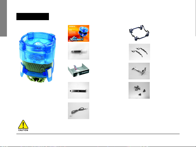
Checklist
(2) GH-PCU23-VE
User's Manual
(7) LGA775 RM
(3) Heat Sink Paste
(4) 3.5" Drive Bay Fan
Speed Controller
(1) GH-PCU23 -VE Cooler
Before use, please remove the protective film from the bottom of the cooler.
Prior to installation, make sure that the computer is turned off and its power is disconnected.
GH-PCU23-VE
(5) PCI Bracket
(6) Power Cable
- 8 -
(8) P4 Clips
(9) AM2 / K8 Clip
(10) Screws
Page 9

Specifications
y Heat Sink Dimension : 112 x 112 x 175 mm
y Fan Dimension : 92 x 92 x 25 mm
y Heat Pipe Number : 4
y Base Material : Copper
y Fin Material : Aluminum
y Rated Voltage : 12V
y Rated Current : 0.38A
y Fan Speed : 1,500 ~ 3,000 RPM
y Noise : 16 ~ 33.5 dBA
y Bearing Type : Ball Bearing
y Life Expectancy : 50,000 hr
y Compatible CPU :
®
Intel
Pentium® Extreme Edition 955/840
®
Pentium® D Processor 960/840
Intel
Intel® PentiumR 4 Processor 670/570
®
Pentium® 4 478 3.4GHz
Intel
AMD AM2 Series
AMD Athlon
AMD Athlon
AMD Athlon
TM
FX62
TM
64x2 5200+
TM
64 4000+
Features
y Dual Rocket Airflow Design Fan Duct - for better performance and silent environment
y Four high conductivity heat pipes design
y High density precise forging copper bottom
y Super large aluminum fins for more thermal area
y Linear fan speed control on 3.5'' front panel or rear PCI bracket
y Changeable fluorescent rings (Blue / Green / White / Orange)
- 9 -
English
GH-PCU23-VE
Page 10

Installation Instructions for Intel® Pentium® 4 LGA775 RM & Cooler
English
ARM
Side A
Side B
CAM
Figure 2.
On the underside of the motherboard, secure a screw with a washer in one of the four holes
Plastic
located adjecent to the processor socket. And do the same for the remaining three holes.
Washers
Figure 2
Figure 3-1 Figure 3-2 Figure 3-3
To install P4 clips, please refer to "Installation Instructions for Intel® Pentium® 4 mPGA478 Cooler & Clips."
GH-PCU23-VE
Figure 1
Figure 1.
Place the LGA775 RM onto the LGA775
motherboard so that side A is paralleled with the
ARM and side B is paralleled with the CAM.
Figure 3.
Place the cooler on the CPU socket and secure it
with the P4 clips (Figure 3-1). Connect the 3-pin fan
cable connector of the cooler to the motherboard
CPU fan header
is now complete
- 10 -
(Figure 3-2). Then the installation
(Figure 3-3).
Page 11

Installation Instructions for Intel® Pentium® 4 mPGA478 Cooler & Clips
Figure 1.
Apply a thin layer of heat sink paste to the surface of the CPU
1-1) and then place the cooler atop the CPU (Figure 1-2).
Figure 1-1
Figure 2-1
Figure 3-1
Please refer to page 13 & 14 for power connection and installation of the fan speed controller.
Figure 1-2
Figure 2-2
Figure 3-2
Figure 2.
Hook one end of the clip to one of the RM hooks
(Figure 2-1). Secure the
other end to the hook on the other side by pushing down on the handle
(Figure 2-2). Do the same for the other clip.
Figure 3.
Connect the 3-pin fan cable connector of the cooler to the motherboard
CPU fan header (Figure 3-1). Then the installation is now complete
(Figure 3-2).
- 11 -
English
(Figure
GH-PCU23-VE
Page 12

Installation Instructions for AMD AM2 / K8 Cooler & Clip
English
Figure 1-1
Figure 2-1
Figure 3-1 Figure 3-2 Figure 3-3
Please refer to page 13 & 14 for power connection and
installation of the fan speed controller.
GH-PCU23-VE
Figure 1-2 Figure 1-3
Figure 2.
Align and secure one side of the clip (Figure 2-1). On the other side , also
align the clip with the mounting lugs and then carefully push straight down
on the clip to hook it to the retention frame. For AM2 CPU, hook the clip to
Figure 2-2
the center mounting lug on the retention frame
- 12 -
Figure 1.
Apply a thin layer of heat sink paste to the surface
of the CPU (Figure 1-1). Put the AM2/K8 clip on to
the cooler as shown in Figure 1-2. Put the cooler
onto the CPU
(Figure 1-3).
(Figure 2-2).
Figure 3.
Close the clip lever as shown in Figure 3-1 and
Figure 3-2 to secure it to the retention frame.
Connect the fan cable connector of the cooler to
the motherboard CPU fan header. Then the
installation is now complete
(Figure 3-3).
Page 13

Power Connection and Installation of the 3.5" Drive Bay Fan Speed Controller
Figure 1.
Connect one end of the provided power cable to the 3-pin header on
the cooler (Figure 1-2).
English
Figure 1-1
Figure 2
Figure 3-1
Figure 4
Figure 1-2
Figure 3-2
Figure 2.
Connect the other end to the motherboard 3-pin or 4-pin CPU fan
header (Figure 2).
Figure 3.
Secure the 3.5" drive bay fan speed controller in a free drive bay with
the provided screws
from the controller to the small 3-pin header on the cooler
(Figure 3-1). Connect the small 3-pin power cable
(Figure 3-2).
Figure 4.
Start your computer after the installation is complete. If there is an item
that allows for CPU fan speed control in system BIOS Setup, disable the
function. Use the fan speed controller to adjust the fan speed based on
your requirements.
- 13 -
GH-PCU23-VE
Page 14

Power Connection and Installation of the PCI Slot Bracket Fan Speed Controller
English
Figure 1-1
Figure 2
Figure 3-1
Figure 4
GH-PCU23-VE
Figure 1-2
Figure 3-2
Figure 1.
Remove the knob, bolt and controller from the 3.5" drive bay fan speed
controller panel in sequence (Figure 1-1). Secure the controller, then the
bolt and finally the knob to the PCI bracket (Figure 1-2).
Figure 2.
Place the PCI bracket with the fan speed controller in the selected PCI
slot. Use screws to secure the PCI bracket in place.
Figure 3.
Connect one end of the provided power cable to the 3-pin header on
the cooler (Figure 3-1). Connect the other end to the motherboard 3-pin
or 4-pin CPU fan header. Connect the small 3-pin power cable from
the controller to the small 3-pin header on the cooler
Figure 4.
Start your computer after the installation is complete. If there is an item
that allows for CPU fan speed control in system BIOS Setup, disable the
function. Use the fan speed controller to adjust the fan speed based on
your requirements.
- 14 -
(Figure 3-2).
Page 15

Special Design
yy
y Changeable Fluorescent Rings
yy
y Fluorescent Ring
yy
yy
y Dual Fan Duct Design
yy
yy
y Dual Rocket Airflow Design Fan Duct
yy
For better performance and silent environment. To achieve the best cooling effect, place the sealed side
toward the inside of the case.
Sealed Side
y
Air Outlet Side y
Install the upper fan duct depending on the case you use.
y Air Outlet Side
yy
(Colors: Blue / Green / White / Orange)
Air Outlet Side y
y Sealed Side
English
- 15 -
GH-PCU23-VE
Page 16

Intel® Pentium® 4 LGA775 / mPGA478
AMD AM2 / K8
GH-PCU23-VE
REV.1001
Page 17

............................................................................................................... 18
................................................................................................................ 19
............................................................................................................... 19
Intel® Pentium® 4 LGA775 ............................................ 20
Intel® Pentium® 4 mPGA478 ......................................... 21
AMD AM2 / K8 ............................................................ 22
3.5 .................................................. 23
PCI .................................................................. 24
............................................................................................................... 25
Page 18

(2) GH-PCU23-VE
(7) LGA775
(1) GH-PCU23 -VE
GH-PCU23-VE
(3)
(4) 3.5
(5) PCI
(6)
- 18 -
(8) P4
(9) AM2 / K8
(10)
Page 19

y 112 x 112 x 175 mm
y
y
92 x 92 x 25 mm
4
y
y
y 12V
y
0.38
y 1,500 ~ 3,000 RPM
y
y
16 ~ 33.5 dBA
Ball Bearing
y
50,000
y
Intel® Pentium® Extreme Edition 955/840
®
Pentium® D Processor 960/840
Intel
Intel® PentiumR 4 Processor 670/570
®
Pentium® 4 478 3.4GHz
Intel
AMD AM2 Series
AMD Athlon
AMD Athlon
AMD Athlon
TM
FX62
TM
64x2 5200+
TM
64 4000+
y
y
y
y
y ( 3.5 PCI )
y Gamer
( / / / )
- 19 -
GH-PCU23-VE
Page 20

Intel® Pentium® 4 LGA775
A
2
3-1 3-2 3-3
B
2.
1.
LGA775 LGA775
A LGA775
1
B LGA775
3.
LGA775 P4
( 3-1)
CPU_FAN ( 3-2)
( 3-3)
GH-PCU23-VE
P4 "Intel® Pentium® 4 mPGA478 "
23 24
- 20 -
Page 21

Intel® Pentium® 4 mPGA478
1-1
2-1
1-2
2-2
1.
CPU ( 1-1)
CPU ( 1-2)
2.
P4 CPU (
2-1) CPU ( 2-2)
P4 CPU
3.
CPU_FAN ( 3-1)
( 3-2)
3-1
3-2
23 24
- 21 -
GH-PCU23-VE
Page 22

AMD AM2 / K8
1-1
1-2 1-3
1.
CPU ( 1-1)
( 1-2)
CPU ( 1-3)
2.
AM2 / K8 K8 CPU
2-1
3-1 3-2 3-3
2-2
GH-PCU23-VE
( 2-1) AM2 CPU CPU
( 2-2)
3.
CPU
( 3-1, 3-2)
CPU_FAN
( 3-3)
23 24
- 22 -
Page 23

3.5
1.
3-pin
( 1-2)
1-1
1-2
2.
3-pin 4-pin
CPU_FAN
2
3.
3.5
( 3-1) 3-pin
3-pin ( 3-2)
3-1
3-2
4.
BIOS
4
- 23 -
GH-PCU23-VE
Page 24

PCI
1.
3.5
( 1-1) PCI ( 1-2)
1-1
2
3-1
4
GH-PCU23-VE
1-2
2.
PCI PCI
3.
3-pin
( 3-1) 3-pin 4-
pin CPU_FAN PCI 3-pin
3-2
3-pin ( 3-2)
4.
BIOS
- 24 -
Page 25

yy
y
yy
yy
y Gamer
yy
y
yy
yy
y
yy
yy
( / / / )
y
y
y
- 25 -
y
y
GH-PCU23-VE
 Loading...