

Page 1
GH - W IU 0 2
Caution
1. For a detailed installation process, please refer to the c omplete version of the manual
2. Before pouring liquid coolant into the tank to test the liquid cooling system, please reconrm
all the tubes have been fastened and the tube clips are in the right position.
3. While the liquid in the tank is lower than the low water-level, the red light on the bottom of
the PCB will blink. ( Please purc hase GIG ABYT ETM liquid c oolant to ll it )
4. When the liquid is lower than the low water-level, the system will turn off automatically
within four seconds after detection of water inadequacy.
5. While removing the tubes for disassembly, please make sure to keep all the devices away
from any electronic part. ( P lease ref er to disas sembly proces s instru ction )
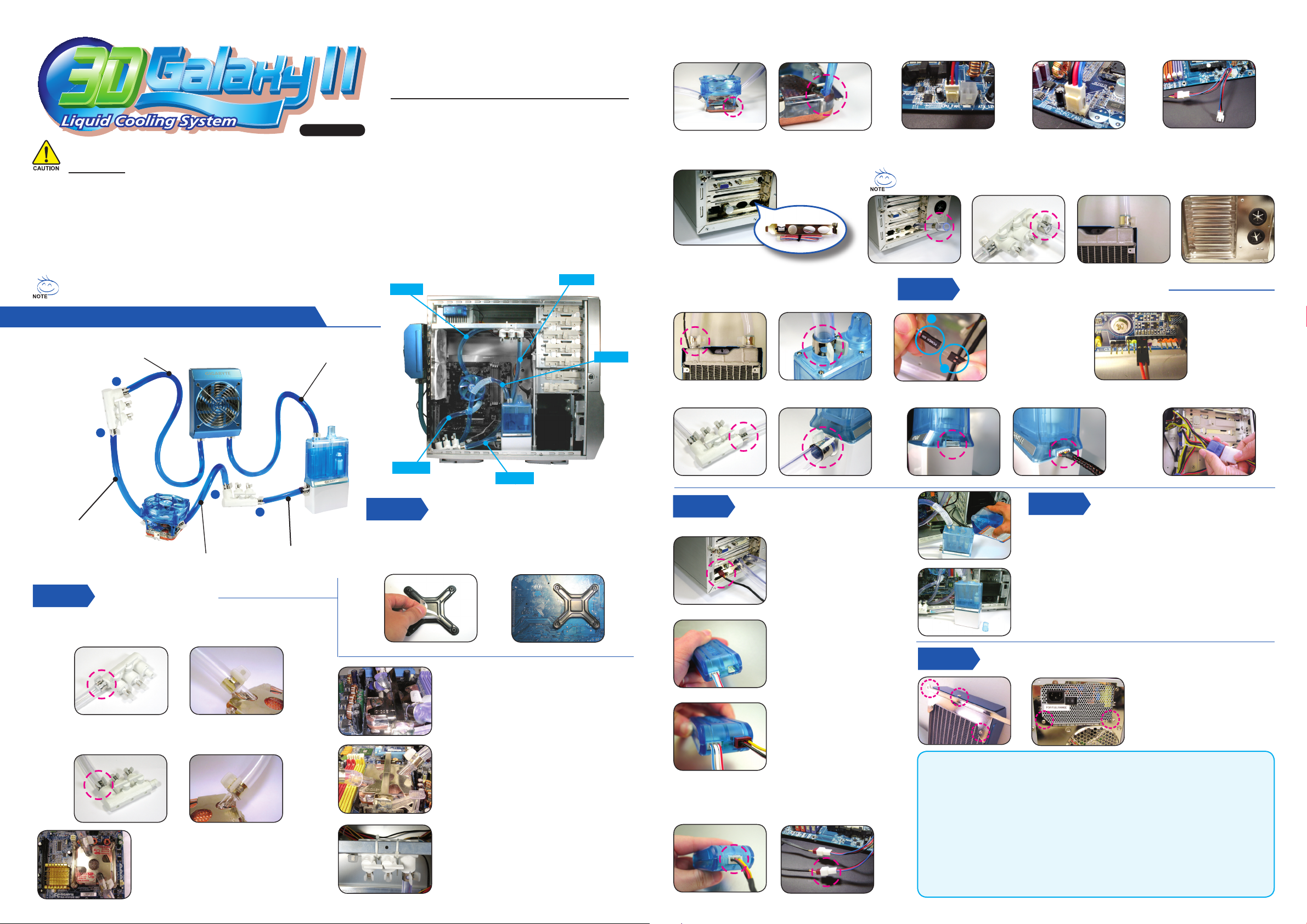
After measuring the distance between the parts of the cooling system, cut the tubes
into ve suitable pieces as shown below. To get the right length for each tube, it is
strongly recommended to t all the components in the right position.
Liquid Cooling System complete installation diagram
Tube3 : The inlet of radiator to
4-way splitter valve (1)
B
Tube4 : The outlet of radiator
to the inlet of the tank
Quick Installation Guide
Accessories
01) Radiator
02) Pump + Tank Assembly
03) MOSFET A ir Cooling Fan
04) Waterblock
05) 4-Way Splitter Valve ( 2 p cs )
06) 1/2 Inch Tube
07) Tube Clips ( 8 pcs )
08) Screws
09) Intel® Pentium®4 LGA775
Spring Screws
10) Intel® Pentium®4 LGA775
Back Plate
11) Intel® Pentium®4 LGA775
Bracket
12) AMD K8 Clip
Tube1
13) AMD Bracket
14) Fan Speed Control Box
15) PCI rear fan speed control panel
16) Radiator Rack
17) Pump Power Cord
18) Fan 1 to 2 Power Cord
19) Fan speed control Power Cord
20) Heat Sink for Memor y ( 8 pcs )
21) Bend Proof Spring
22) Nylon Tie ( 4pcs )
23) Grease
24) GIGABYTETM Liquid Coolant
25) Velcro
26) Installation Guide
Tube 3
Tube 4
2-5 Place the MOSFET air cooling fan on the top of
waterblock and make sure that the four feet of MOSFET
air cooling fan are r mly locked to the waterblock.
2-8 Place PCI slot fan speed controller at the
rear of the chassis. (Pl ace on the middle or low er PCI
slot is rec ommended )
2-9 Thread Tube 3 through the hole on PCI slot ( as Figure a ) to connect one side of tube 3 with 4-way splitter valve (1)
B and fasten it with tube clips ( as Figure b ), and connect the other side of tube 3 with the inlet of radiator and
fasten it with tube clips ( as Figure c ).
2-10 Thread Tube 4 through the hole on PCI slot to
connect one side of tube 4 with the outlet of radiator
and fasten it with tube clips, and connect the other
side of tube 4 with the inlet of the tank and fasten it
with clips.
2-11 Use tube 5 to be connec t 4-way splitter valve with
outlet of the tank and fasten it with tube clips.
2-6 Plug the 1 to 2 power c ord of the fan in socket of the CPU
FAN on the montherboard ( Figure a : 3 -pin C PU fan soc ket /
Figure b : 4 -pin CPU fan socket ( Intel
For GIGABYTETM 3D Aurora、Triton or Poseidon series chassis user, the tube can be threaded through
drainage inlet / outlet on the chassis. ( as the right two holes in Figure d )
< Figure a > < Figure b > < Figure c > < Figure d >
Step 3
a
Pump Power Cord Installation
b
®
®
Pentium
4 LGA775) )
< Figure a > < Figure b >
3-1 Connect the Power
SW ( female 2-pin )
from the chassis’s
panel with the
pump
power cord male
2-pin.
3-3 Connect the pump power cord 6-pin connector with the
back of the tank. ( as gure a / b )
2-7 Plug the 1 to 2 power cord’s 3 pin male
connector into socket of the SYS FAN
on the motherboard as shown.
3-2 Connect the pump
power SW cord
female 2-pin with
“+PW-“ jumper on
the motherboard.
3-4 Connect 4-pin power supply connector
with the 4 -pin pump cord connector.
A
B
Tube1 : 4-way splitter valve (1)
to the outlet of the
waterblack
Step 2
Tube2 : 4-way splitter valve (2)
to the inlet of the waterblock
Tube Installation
Tube5 : 4-way splitter valve (2)
to the outlet of the tank
2-1 Connect one side of tube 1 with 4-way splitter valve (1) A as shown in
the picture and fasten it with tube clip; connect the other side of tube 1
with the outlet of waterblock and fasten it with tube clip.
2-2 Connect one side of tube 2 with 4-way splitter valve (2) B as shown
in the gure and fasten it with tube clip; connect the other side of tube
2 with the inlet of waterblock and fasten it with tube clip.
2-3-1 Place the waterblock on the top of Intel
Pentium® 4 LGA775 CPU, and secure with
attached Intel® Pentium® 4 LGA775 Bracket.
( For detail i nstall ation ste p of Intel
please re fer to Intel® Pentium® 4 Clip inst allatio n and
waterbl ock inst allati on instr uction )
A
®
Pentium® 4 Clips,
Tube 2
Tube 5
Step 1
H Take off the double -side sticker on the Intel
Plate ( as Figure a ), and stick it on the back of Intel® Pentium®4 LGA775
CPU with aligning four holes on Intel® Pentium®4 LGA775 Back Plate and
four holes on the back of Pentium4® LGA775 CPU motherboard (as Figure b).
Intel® Pentium4® LGA775 Back Plate
Installation ( FO R AMD series CPU p lease ignore this step)
®
Pentium®4 LGA775 Back
< Figure a >
< Figure b >
Step 4
2-3-2 Place the waterblock on AMD K8 retention
mechanism, and secure with attached A MD
K8 retention mechanism kit.
( For detail in stallati on step of AMD K8 Clips, p lease refer t o
AMD K8 Clip i nstallat ion and waterblock i nstallat ion instr uction )
2-3-3 Place the waterblock on AMD AM2 retention
mechanism, and secure with attached A MD
AM2 retention mechanism kit.
( For detail in stallati on step of AMD AM2 Clip s , please refer to
AMD AM2 C lips installation a nd waterbl ock insta llation in struct ion )
®
2-4 Using the nylon tie to fasten 4-way splitter valve
on trestle of the chassis. If there is no trestle
available, tr y to nd an applicable place to
fasten it.
4-4 To accomplish installation, plug the power c ord for fan
speed control box in the connector on the fan speed control
box (as Figure a) and plug the other side of the power cord in the
available 1 to 2 socket (as Figure b).
Radiator Speed Control
Box Installation
4-1 Thread the radiator fan
connector through the hole
of PCI slot fan speed
control panel.
4-2 Plug the connector from the
PCI slot fan speed control panel
in the fan speed control box.
4-3 Plug the radiator fan power
cord in the fan speed
control box.
< Figure a > < Figure b >
Step 6
Warning :
1. While relling liquid c oolant, please remove the tank from the chassis to prevent other
components from improper relling of liquid coolant.
2. Before turning on the power, please conrm that all the tube clips are fastened; leakage of liquid
coolant due to improper installation may damage the system that is not c overed by warranty.
3. Use only GIGABYTETM liquid coolant; any damage arising from using other liquid product is not
covered by warranty.
4. Be aware of abnormal leakage. If the installation was correct and the tubes are fastened, and the
liquid cooling system leaks please turn of f the power immediately, and drain out all the coolant.
Contact GIGABY TETM dealers or GIGABY TETM service center.
5. For the rst time of pouring liquid coolant into the tank; the radiator should be lay down at to
facilitate exhaust air to ensure the liquid cooling system to function silently; and then install the
radiator in accordance with the instruction. Make sure all the air bubble in the tube has
been removed to ensure the performance of cooling.
< Figure a > < Figure b >
Step 5
Pour in Liquid Coolant
5-1 Open the lid of the tank to pour in liquid coolant and close
the lid.
5-2 Turn on the power until all liquid coolant drains into
the tubes; the red light on the bottom of PCB will blink
and bleep; the system will turn off automatically within
4 seconds. ( This is nor mal at this point sinc e the tube
and radiato r are not full of liquid. )
5-3 Open the lid of the tank again to rell it with liquid coolant
and close it. Turn on the power one more time and repeat
this step until the water is no longer lower than low water level.
Radiator Installation
6-1 Fix the radiator rack to the radiator
with 3 x M3 screws
6-2 Remove the 2 screws on the power
supply at the rear of chassis as
shown.
6-3 To accomplish liquid cooling
system, align the 2 screw hole on
the radiator rack to the 2 screw
holes on the power supply and
fasten them up.
 Loading...