

Gigabit Systems JPEG2000 Communication Protocol Manual

JPEG2000 HDTV RECORDER
JP2pro series
RS422 Communication protocol
Rev. 16.1
Gigabit Systems Inc.
WWW.gigabitsystems.com

INDEX
Structure of the communication dat a......................................................................................................7
VTR compatible command format........................................................................................................... 7
JP2pro recorder dedicated protocol command format..........................................................................9
Connection pin assignment................................................................................................................... 10
Communication protocol ........................................................................................................................11
RS-422A VTR compatible command list.................................................................................................. 12
RS-422A JP2pro recorder protocol command list ................................................................................... 14
Explanation of each command and response...................................................................................... 17
00 11 DEVICE TYPE REQUEST ......................................................................................................... 17
12 11 DEVICE TYPE............................................................................................................................ 17
10 01 ACK............................................................................................................................................ 17
11 12 NAK ............................................................................................................................................ 18
20 00 STOP.......................................................................................................................................... 18
21 00 STOP (JP2pro only)...................................................................................................................19
20 01 PLAY........................................................................................................................................... 19
20 02 RECORD.................................................................................................................................... 20
22 02 RECORD (interval recording)..................................................................................................... 20
20 04 STANDBY OFF........................................................................................................................... 21
20 05 STANDBY ON............................................................................................................................ 21
20 10 FAST FORWARD.......................................................................................................................21
21 11 JOG FORW ARD......................................................................................................................... 22
21 12 VARIABLE FORWARD............................................................................................................... 22
21 13 SHUTTLE FORWARD................................................................................................................23
20 14 STEP FORWARD....................................................................................................................... 23
20 20 REWIND..................................................................................................................................... 23
21 21 JOG REVERSE.......................................................................................................................... 24
21 22 VARIABLE REVERSE................................................................................................................ 24
21 23 SHUTTLE REVERSE................................................................................................................. 24
20 24 STEP REVERSE........................................................................................................................ 25
24 30 PREROLL WITH DATA.............................................................................................................. 25
24 31 CUEUP WITH DATA................................................................................................................... 26
20 60 FULL EE OFF............................................................................................................................. 26
20 61 FULL EE ON...............................................................................................................................27
20 63 SELECT EE OFF ....................................................................................................................... 27
20 64 EDIT OFF................................................................................................................................... 27
20 65 EDIT ON..................................................................................................................................... 28
44 00 TIMER-1 PRESET...................................................................................................................... 28
44 04 TIME CODE PRESET................................................................................................................ 29
1

45 05 USER BIT PRESET ................................................................................................................... 30
40 08 TIMER-1 RESET........................................................................................................................ 31
41 30 EDIT PRESET............................................................................................................................ 31
44 31 PREROLL TIME PRESET.......................................................................................................... 32
41 36 TIMER MODE SELECT ............................................................................................................. 32
41 38 PB FIELD/FRAME SELECT....................................................................................................... 33
61 0A TIME CODE GENERATOR DATA SENSE ................................................................................ 34
61 0C CURRENT TIME SENSE .......................................................................................................... 35
61 20 STATUS SENSE......................................................................................................................... 36
61 30 EDIT PRESET SENSE............................................................................................................... 36
60 31 PREROLL TIME SENSE............................................................................................................ 37
60 36 TIMER MODE SENSE............................................................................................................... 37
74 00 TIMER-1 DATA........................................................................................................................... 37
74 04 LTC TIME DATA.........................................................................................................................38
78 04 LTC TIME & UB DATA............................................................................................................. 38
74 05 LTC UB DATA............................................................................................................................. 39
74 06 VITC TIME DATA........................................................................................................................ 39
78 06 VITC TIME & UB DATA ........................................................................................................... 40
74 07 VITC UB DATA...........................................................................................................................40
74 08 TC GEN DATA............................................................................................................................ 41
74 09 UB GEN DATA............................................................................................................................ 41
78 0A TCG & UBG DATA................................................................................................................... 42
7X 20 STATUS DATA........................................................................................................................... 43
71 30 EDIT PRESET DATA.................................................................................................................. 47
74 31 PREROLL TIME DATA............................................................................................................... 47
71 36 TIMER MODE STATUS.............................................................................................................. 48
82 06 GO TO FILE...............................................................................................................................48
3E 03 32 00 DISK FORMAT................................................................................................................. 49
3E 00 32 01 DISK STATUS SENSE..................................................................................................... 49
3E 18 33 01 DISK STATUS DATA........................................................................................................ 50
3E 00 32 02 SERIAL NO. REQUEST.................................................................................................. 51
3E 0A 33 02 SERIAL NO. DATA........................................................................................................... 51
3E 19 32 03 NETWORK CONFIGURATION PRESET........................................................................ 52
3E 00 32 04 NETWORK CONFIGURATION REQUEST.....................................................................53
3E 19 33 03 NETWORK CONFIGURATION DATA ............................................................................. 53
3E 00 32 05 SYSTEM STATUS REQUEST......................................................................................... 54
3E 01 33 05 SYSTEM STATUS DATA................................................................................................. 54
3E 01 32 06 DELETE PARTITION....................................................................................................... 55
3E 01 32 07 CHANGE PARTITION...................................................................................................... 56
3E 01 32 08 PARTITION STATUS REQUEST..................................................................................... 57
2

3E 0B 33 08 PARTITION STATUS DATA............................................................................................. 57
3E 01 34 00 STOP............................................................................................................................... 58
3E 00 34 01 PLAY................................................................................................................................58
3E 00 34 02 RECORD ......................................................................................................................... 59
3E 00 34 10 FAST FORW ARD.............................................................................................................59
3E 01 34 11 JOG FORW ARD..............................................................................................................60
3E 01 34 12 VARIABLE FORWARD.................................................................................................... 60
3E 01 34 13 SHUTTLE FORWARD.....................................................................................................61
3E 00 34 14 STEP FORWARD ............................................................................................................ 61
3E 00 34 20 REWIND .......................................................................................................................... 61
3E 01 34 21 JOG REVERSE............................................................................................................... 62
3E 01 34 22 VARIABLE REVERSE..................................................................................................... 62
3E 01 34 23 SHUTTLE REVERSE...................................................................................................... 63
3E 00 34 24 STEP REVERSE............................................................................................................. 63
3E 04 34 30 PREROLL WITH DATA.................................................................................................... 64
3E 04 34 31 CUEUP WITH DATA........................................................................................................ 65
3E 00 34 40 FULL EE OFF..................................................................................................................65
3E 00 34 41 FULL EE ON.................................................................................................................... 66
3E 00 34 43 SELECT EE ON............................................................................................................... 66
3E 00 34 44 EDIT OFF......................................................................................................................... 66
3E 00 34 45 EDIT ON .......................................................................................................................... 67
3E 00 34 46 CHASE............................................................................................................................. 67
3E 03 34 50 OPEN FILE......................................................................................................................68
3E 00 34 51 DELETE LAST FILE........................................................................................................ 68
3E 03 34 52 GO TO CLIP .................................................................................................................... 69
3E 03 34 53 GO TO CUE POINT......................................................................................................... 70
3E 03 34 54 GO TO SEQ..................................................................................................................... 71
3E 01 34 64 VIDEO QUALITY SELECT.............................................................................................. 71
3E 03 34 65 GEN LOCK SELECT....................................................................................................... 72
3E 01 34 66 AUDIO INP UT SELECT................................................................................................... 72
3E 01 34 67 AUDIO CHANNEL SELECT.............................................................................................73
3E 01 34 68 AUDIO SRC (Sampling Rate Converter) SELECT.......................................................... 73
3E 04 34 69 PREROLL TI ME PRESET............................................................................................... 74
3E 01 34 6A VARIABLE AUDIO SELECT............................................................................................ 74
3E 03 34 70 REC PRESET.................................................................................................................. 75
3E 01 34 71 PLAY PRESET................................................................................................................. 76
3E 01 34 72 TCG PRESET.................................................................................................................. 77
3E 04 34 73 TIME CODE PRESET...................................................................................................... 78
3E 05 34 74 USER BIT PRESET......................................................................................................... 79
3E 01 34 75 EDIT PRESET ................................................................................................................. 80
3

3E 02 34 76 TSG PRESET..................................................................................................................81
3E 01 34 77 AUDIO DELAY PRESET.................................................................................................. 81
3E 0B 34 78 CHARACTER PRESET................................................................................................... 82
3E 01 34 79 VANC PRESET................................................................................................................ 83
3E 01 34 7A TIMER MODE PRESET.................................................................................................. 84
3E 04 34 7B TIMER-1 PRESET........................................................................................................... 84
3E 01 34 7C CHASE PRESET ............................................................................................................ 85
3E 27 34 80 CUE POINT PRESET...................................................................................................... 86
3E 2D 34 81 CLIP DATA PRESET....................................................................................................... 87
3E 22 34 82 FILE DATA PRESET........................................................................................................ 88
3E 00 34 83 CUE POINT RESET........................................................................................................ 88
3E 00 34 84 CLIP DATA RESET..........................................................................................................88
3E 05 34 85 SEQ EDIT........................................................................................................................ 89
3E 00 34 86 SEQ DATA RESET .......................................................................................................... 89
3E 02 34 87 H PHASE PRESET.......................................................................................................... 90
3E 02 34 88 V PHASE PRESET.......................................................................................................... 90
3E 00 34 89 ERROR CODE RESET ................................................................................................... 91
3E 0D 34 8A SEQ DATA LOAD............................................................................................................ 91
3E 01 34 8B STILL MODE PRESET.................................................................................................... 92
3E 03 34 8C FILE INHIBIT PRESET ................................................................................................... 92
3E 21 34 90 SEQ NAME PRESET ...................................................................................................... 93
3E 00 34 91 FACTRY DATA STORE.................................................................................................... 93
3E 00 34 92 FACTRY DATA LOAD ...................................................................................................... 93
3E 02 34 93 THUMB STORE............................................................................................................... 94
3E 02 34 94 THUMB RELOAD............................................................................................................ 94
3E 01 34 95 CODEC PRESET ............................................................................................................ 95
3E 00 36 60 EXTEND STATUS SENSE .............................................................................................. 95
3E 1C 37 60 EXTEND STATUS DATA.................................................................................................96
3E 01 36 61 TIME CODE GENERATOR DATA SENSE....................................................................102
3E 01 36 62 CURRENT TIME SENSE...............................................................................................103
3E 04 37 04 TC TIME DATA............................................................................................................... 104
3E 04 37 05 TC UB DATA..................................................................................................................104
3E 08 37 06 TC TIME & UB DATA .................................................................................................. 105
3E 04 37 08 TC GEN DATA............................................................................................................... 105
3E 04 37 09 UB GEN DATA ............................................................................................................... 106
3E 08 37 0A TC GEN DATA & UB GEN DATA................................................................................106
3E 00 36 63 REMAIN TIME SENSE.................................................................................................. 107
3E 04 37 63 REMAIN TIME DATA..................................................................................................... 107
3E 00 36 64 VIDEO QUALITY SENSE.............................................................................................. 108
3E 01 37 64 VIDEO QUALITY DATA.................................................................................................108
4

3E 00 36 65 GEN LOCK SENSE....................................................................................................... 109
3E 03 37 65 GEN LOCK DATA.......................................................................................................... 109
3E 00 36 66 PLAYBACK TIME SENSE..............................................................................................110
3E 08 37 66 PLAYBACK TIME DATA .................................................................................................1 10
3E 00 36 69 PREROLL TI ME PRESET SENSE.................................................................................111
3E 04 37 69 PREROLL TI ME PRESET DATA....................................................................................111
3E 00 36 6A VARIABLE AUDIO SENSE.............................................................................................112
3E 01 37 6A VARIABLE AUDIO DATA................................................................................................112
3E 00 36 70 REC PRESET SENSE....................................................................................................113
3E 03 37 70 REC PRESET DATA.......................................................................................................113
3E 00 36 71 PLAY PRESET SENSE..................................................................................................114
3E 01 37 71 PLAY PRESET DATA......................................................................................................114
3E 00 36 72 TCG PRESET SENSE....................................................................................................115
3E 01 37 72 TCG PRESET DATA.......................................................................................................115
3E 00 36 75 EDIT PRESET SENSE...................................................................................................116
3E 01 37 75 EDIT PRESET DATA......................................................................................................116
3E 00 36 76 TSG PRESET SENSE....................................................................................................117
3E 01 37 76 TSG PRESET DATA.......................................................................................................117
3E 00 36 77 AUDIO DELAY SENSE...................................................................................................1 18
3E 02 37 77 AUDIO DELAY DATA......................................................................................................118
3E 00 36 78 CHARACTER PRESET SENSE.....................................................................................119
3E 0B 37 78 CHARACTER PRESET DATA........................................................................................119
3E 00 36 79 VANC PRESET SENSE................................................................................................. 120
3E 01 37 79 VANC PRESET DATA.................................................................................................... 120
3E 00 36 7A TIMER MODE PRESET SENSE................................................................................... 121
3E 01 37 7A TIMER MODE PRESET DATA......................................................................................121
3E 00 36 7C CHASE PRESET SENSE............................................................................................. 122
3E 02 37 7C CHASE PRESET DATA ................................................................................................ 122
3E 02 36 80 CUE POINT REQUEST................................................................................................. 123
3E 29 37 80 CUE POINT DATA......................................................................................................... 123
3E 02 36 81 CLIP DATA REQUEST................................................................................................... 124
3E 2E 37 81 CLIP DATA..................................................................................................................... 124
3E 02 36 82 FILE DATA REQUEST................................................................................................... 125
3E 2E 37 82 FILE DATA..................................................................................................................... 125
3E 00 36 83 ERROR CODE REQUEST............................................................................................ 127
3E 01 37 83 ERROR CODE DATA .................................................................................................... 127
3E 01 36 83 ERROR MESSAGE REQUEST..................................................................................... 128
3E 17 37 83 ERROR MESSAGE DATA............................................................................................. 128
3E 01 36 85 SEQ STATUS DATA REQUEST.................................................................................... 129
3E 03 37 85 SEQ STATUS DATA....................................................................................................... 129
5

3E 02 36 86 SEQ DATA REQUEST................................................................................................... 130
3E 0C 37 86 SEQ DATA..................................................................................................................... 130
3E 00 36 87 H PHASE REQUEST..................................................................................................... 131
3E 01 37 87 H PHASE DATA............................................................................................................. 131
3E 00 36 88 V PHASE REQUEST..................................................................................................... 132
3E 01 37 88 V PHASE DATA............................................................................................................. 132
3E 00 36 8B STILL MODE SENSE.................................................................................................... 133
3E 01 37 8B STILL MODE DATA....................................................................................................... 133
3E 02 36 8C FILE INHIBIT SENSE.................................................................................................... 134
3E 03 37 8C FILE INHIBIT DATA....................................................................................................... 134
3E 01 36 90 SEQ NAME REQUEST ................................................................................................. 135
3E 21 37 90 SEQ NAME DATA.......................................................................................................... 135
3E 02 36 93 THUMB LENGTH REQUEST........................................................................................ 136
3E 12 37 93 THUMB LENGTH DATA ................................................................................................ 136
3E 03 36 94 THUMB DATA REQUEST..............................................................................................137
3E XX 37 94 THUMB DATA............................................................................................................... 138
3E 00 36 95 CODEC PRESET SENSE.............................................................................................139
3E 01 37 95 CODEC PRESET DATA................................................................................................ 139
APPENDIX A “ERROR CODE LIST”..................................................................................................... 140
6

Outline
JP2pro recorder has a D-SUB 9-pin (female) connector on the rear panel used for the EIA
RS-422A serial remote control. Various controllers with the same protocol can be used as remote
controllers
The following description explains the communication protocol of the RS-422A .
Structure of the communication data
・ Full duplex communication channel
・ Asynchronous bit-serial and word serial data transmission
・ Standard transfer rate of 38.4 kbits/s.
・ Syntax: 1 Start bit+8 Data bits+1 Parity bit+1 Stop bit
Start
bit
D0
(LSB)
D1 D2 D3 D4 D5 D6 D7
(MSB)
Mark
Parity
(Odd)
(Note 1) “Odd parity”. The sum of the D0-D7 and the parity bit corresponds to an odd
number.
(Note 2) Mark: Voltage on Line B is higher than that on Line A.
Space: Voltage on Line A is higher than that on Line B.
VTR compatible command format
Communication between control system and the JP2pro recorder uses the following
command format. Composed of CMD 1/Data count, CMD 2, DATA and CHECKSUM. If
the Data count is zero, no data is transmitted. If it is not zero, the data corresponds to
the existing values are inserted between CMD 2 and CHECKSUM.
Bit
4-7
CMD 1 Data
Bit
0-3
CMD 2 DATA 1 -------- DATA N
CHECKSUM
Space
count
N=15max
7
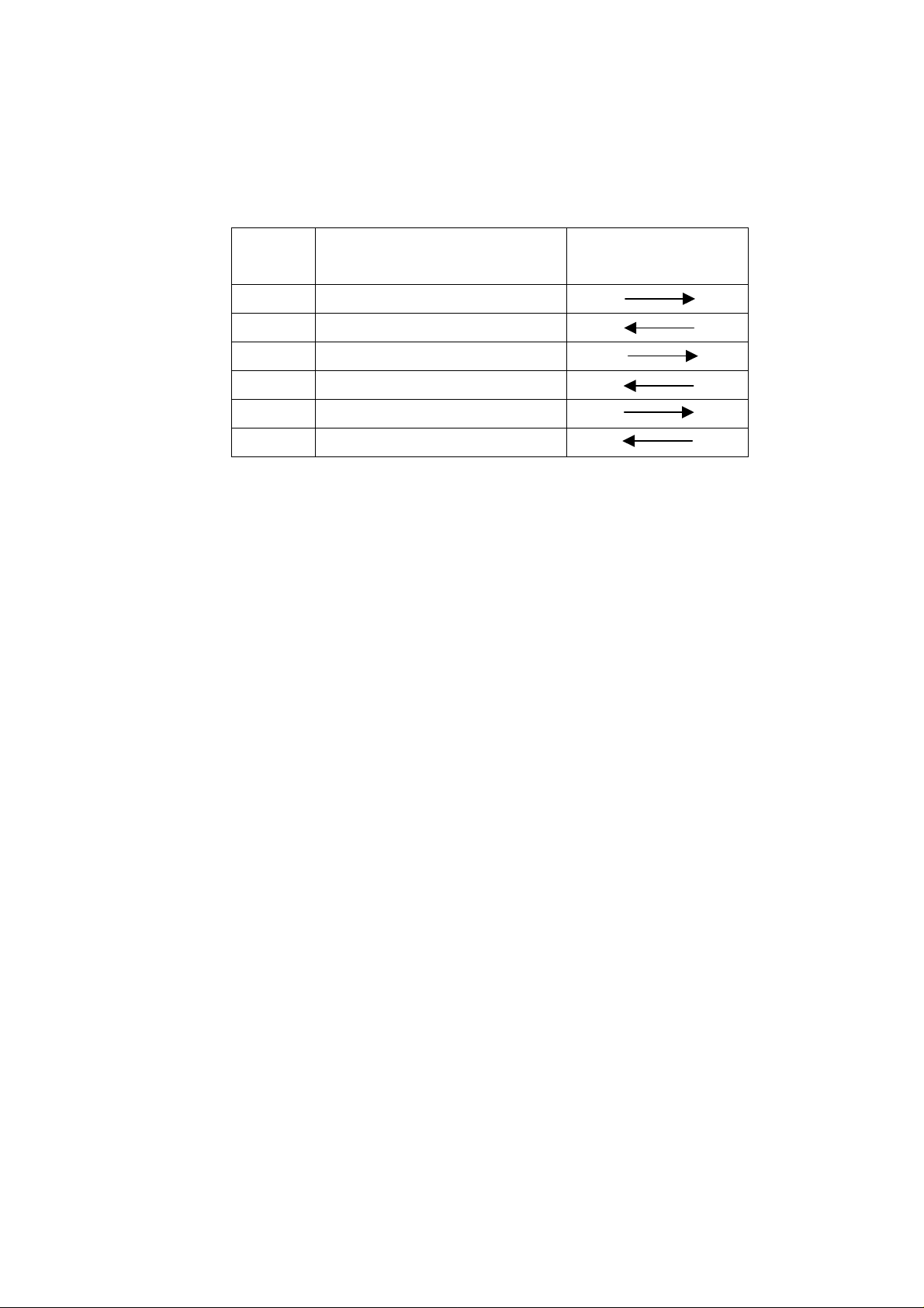
CMD 1: CMD 1 assigns the command to the following main function groups, which
serves to define the function and transfer direction of the data words which follows (See
table below):
CMD 1 Function Transfer direction
Controller---Recorder
0 System control
1 System control-Return message
2 Recorder control
4 Setup and selection control
8 Data request
7 Data request-Return message
Data count: Defines the number of the data words that are inserted after CMD 2.
CMD 2: Is the specific command to the recorder or the command return message from
the recorder, respectively.
DATA: The number of data words and their contents are defined by the CMD 2
command.
CHECKSUM: The sum of the data (D0 to D7) contained in each data word, from
CMD1/DATA COUNT up to the last data word before the checksum. The Checksum is
used to verify that the data are error free and makes sure that transmission sequences,
which are affected by bit errors, are rejected.
8
JP2pro recorder dedicated protocol command format
JP2pro recorder supports dedicated commands. The following description explains the
dedicated command format. It composed by extension code, Data length, CMD 1, CMD
2, DATA and CHECKSUM. If the data length is zero, no data is transmitted. If the data
length is not zero, the data corresponding to the existing values are inserted between
CMD2 and CHECKSUM.
0x3E
Data
length
CMD 1 CMD 2 DATA1 DATA N
N=
Max 255
CHECKSUM
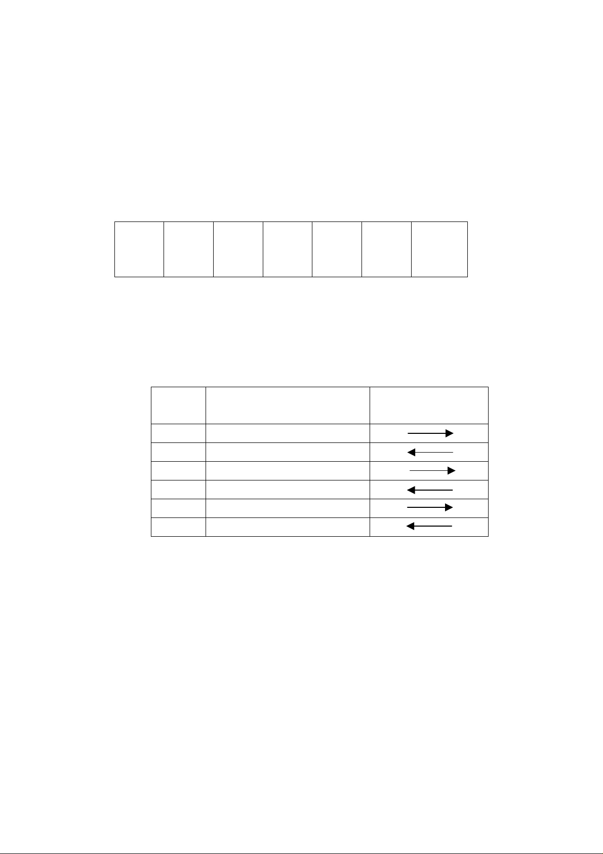
CMD 1: CMD 1 assigns the command to the following main function groups, which
serves to define the function and transfer direction of the data words which follows (See
table below):
CMD 1 Function Transfer direction
Controller---Recorder
0x32 System control
0x33 System control-Return message
0x34 Recorder control
0x35 Setup and selection control
0x36 Data request
0x37 Data request-Return message
Data length: Defines the number of the data words that are inserted after CMD 2.
CMD 2: Is the specific command to the recorder or the command return message from
the recorder, respectively.
DATA: The number of data words and their contents are defined by the CMD 2
command.
CHECKSUM: The sum of the data (D0 to D7) contained in each data word, from the
extension code (0x3E) up to the last data word before the checksum.
9
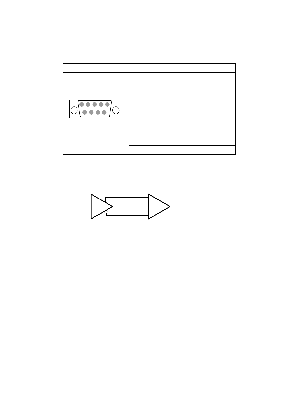
Connection pin assignment
The D-SUB 9-pin connector pin assignment is shown in the table below .
Pin number Signal
1 GND
2 TX-A
5
9
D-SUB 9-pin 8 RX-A
Female 9 GND
A and B are defined as shown below.
1
3 RX-B
4 GND
5 NC
6
6 GND
7 TX-B
B
+
A
-
10

Communication protocol
When the recorder receives the command from the control system, it sends back the
following return massage.
・ If the recorder receives a command without data request:
---ACK (10h, 01h)=acknowledge of receipt.
・ If the recorder receives a command with data request:
---Answer code +data.
・ If transmission error is detected or if an undefined command is received:
---NAK (11h, 12h)+error code
Error code:
Bit0 (01h)= Command not defined
Bit2 (04h)= Checksum error
Bit4 (10h)= Parity error
Bit5 (20h)= Overrun error
Bit6 (40h)= Start/stop bit error (framing error)
Bit7 (80h)= Time out
The control system must not send any additional command before having received a
corresponding response to the previous command.
The control system must not interrupt a transmission of a command for more than 10 ms.
As soon as the recorder has detected such a break which is longer than 10 ms, it
proceed with a time out error sequence. The recorder ignores the command received
and transmits a NAK (time out).
As soon as the recorder receives the command from the control system, it sends the
return message within 9 ms. Therefore, unless having the return message from the
recorder within 10 ms, after the execution of a command transmission, the control
system must proceed as if the communication had not taken place under normal
circumstances.
When an error is detected, the recorder immediately sends a NAK to the control system.
Upon receipt of a NAK, the control system in turn must immediately abort the data block
transmission.
11

RS-422A VTR compatible command list
CODE Command Data Response
00 11 DEVICE TYPE REQUEST 12 11 XX YY
20 00 STOP 10 01 (ACK)
21 00 STOP Stop flag 10 01
20 01 PLAY 10 01
20 02 RECORD 10 01
20 04 STANDBY OFF 10 01
20 05 STANDBY ON 10 01
20 10 FAST FWD 10 01
21 11 JOG FWD Speed 10 01
21 12 VAR FWD Speed 10 01
21 13 SHUTTLE FWD Speed 10 01
20 14 STEP FWD 10 01
20 20 REWIND 10 01
21 21 JOG REV Speed 10 01
21 22 VAR RVS Speed 10 01
21 23 SHUTTLE REV Speed 10 01
20 24 STEP REV 10 01
24 31 CUE UP WITH DATA Time 10 01
20 60 FULL EE OFF 10 01
20 61 FULL EE ON 10 01
20 63 SELECT EE ON 10 01
20 64 EDIT OFF 10 01
20 65 EDIT ON 10 01
44 00 TIMER-1 PRESET Time 1001
44 04 TIME CODE PRESET Time 10 01
45 05 USER BIT PRESET UB 10 01
44 08 TIMER-1 RESET Time 1001
41 30 EDIT PRESET Parameter 10 01
41 31 PRERPLL TIME PRESET Time 1001
41 36 TIMER MODE SELECT Timer mode 1001
41 38 STOP MODE SELECT Stop mode 1001
61 0A TCG DATA SENSE
61 0C CURRENT TIME SENSE
61 20 STATUS SENSE
60 30 EDIT PRESET SENSE
60 31 PREROLL TIME SENSE
12
7X XX TCG data
7X XX TC data
7X 20 Status data
7X 30 Edit preset
7X 31 Preroll time

60 36 TIMER MODE SENSE
7X 36 Timer mode
82 06 GO TO CLIP Parameter
10 01
13

RS-422A JP2pro recorder protocol command list
CODE Command Data Response
32 00 DISK FORMAT Parameter 10 01(ACK)
32 01 DISK STATUS SENSE 33 01
32 02 SERIAL NO REQUEST 33 02
32 03 NETWORK PRESET Parameter 10 01
32 04 NETWORK REQUEST 33 04
32 05 SYSTEM STATUS SENCE 33 05
32 06 DELETE PARTITION Parameter 1001
32 07 CHANGE PARTITION Parameter 1001
32 08 PARTITION STATUS REQUEST Parameter 33 08
34 00 STOP Parameter 10 01
34 01 PLAY 10 01
34 02 REC 10 01
34 04 STANDBY OFF 10 01
34 05 STANDBY ON 10 01
34 10 FAST FWD 10 01
34 11 JOG FWD Speed 10 01
34 12 VAR FWD Speed 10 01
34 13 SHUTTLE FWD Speed 10 01
34 14 STEP FWD 10 01
34 20 REWIND 10 01
34 21 JOG REV Speed 10 01
34 22 VAR RVS Speed 10 01
34 23 SHUTTLE REV Speed 10 01
34 24 STEP REV 10 01
34 30 PREROLL WITH DATA Time 1001
34 31 CUE UP WITH DATA Time 10 01
34 40 FULL EE OFF 10 01
34 41 FULL EE ON 10 01
34 43 SELECT EE ON 10 01
34 44 EDIT OFF 10 01
34 45 EDIT ON 10 01
34 50 OPEN FILE File No. 10 01
34 51 DELETE LAST FILE 10 01
34 52 GO TO CLIP Clip No. 10 01
34 53 GO TO CUE POINT CUE No. 10 01
34 54 GO TO SEQ SEQ No. 10 01
14

CODE Command Data Response
34 64 VIDEO QUALITY SELECT Parameter 10 01
34 65 GEN LOCK SELECT Parameter 10 01
34 66 AUDIO INPUT SELECT Parameter 10 01
34 67 AUDIO CH SELECT Parameter 10 01
34 68 AUDIO SRC SELECT Parameter 10 01
34 69 PREROLL TIME PRESET Parameter 10 01
34 6A VAR AUDIO SELECT Parameter 10 01
34 70 REC PRESET Parameter 10 01
34 71 PLAY PRESET Parameter 10 01
34 72 TCG PRESET Parameter 10 01
34 73 TIME CODE PRESET Parameter 10 01
34 74 USER BIT PRESET Parameter 10 01
34 75 EDIT PRESET Parameter 10 01
34 76 TSG PRESET Parameter 10 01
34 77 AUDIO DELAY PRESET Parameter
34 78 CHARACTER PRESET Parameter 10 01
34 79 VANC PRESET Parameter 10 01
34 7A TIME MODE PRESET Parameter 10 01
34 7B TIMER-1 PRESET Parameter 10 01
34 80 CUE POINT PRESET Parameter 10 01
34 81 CLIP DATA PRESET Parameter 10 01
34 82 FILE NAME PRESET Parameter 10 01
34 83 CUE POINT RESET 10 01
34 84 CLIP DATA RESET 10 01
34 85 SEQ DATA PRESET Parameter 10 01
34 86 SEQ DATA RESET 10 01
34 87 H PHASE PRESET Parameter 10 01
34 88 V PHASE PRESET Parameter 10 01
34 89 ERROR CODE RESET 10 01
34 8A SEQ DATA EDIT 10 01
10 01
34 8B STILL MODE PRESET 10 01
34 8C FILE INHIBIT PRESET 10 01
36 60 EXTEND STATUS SENSE
36 61 TCG DATA SENSE Parameter 37 08, 37 09, 37 0A
36 62 CURRENT TIME SENSE Parameter 37 04, 37 05, 37 06
36 63 REMAIN TIME SENSE 37 63
36 65 GEN LOCL SENSE 37 65
36 66 PLAYBACK TIME SENSE 37 66
15
37 60

36 69 PREROLL TIME SENSE 37 69
36 70 REC PRESET SENSE 37 70
36 71 PLAY PRESET SENSE 37 71
36 72 TCG PRESET SENSE 37 72
36 73 EDIT SENSE 37 75
36 74 TSG PRESET SENSE 37 76
36 75 AUDIO DELAY SENSE 37 77
36 76 CHARACTER PRESET SENSE 37 78
36 79 VANC PRESET SENSE Parameter 37 79
36 7A TIMER MODE PRESET SENSE 37 7A
36 80 CUE POINT REQUEST 37 80
36 81 CLIP DATA REQUEST 37 81
36 82 FILE DATA REQUEST 37 82
36 83 ERROR CODE REQUEST 37 83
36 85 SEQ DATA REQUEST 37 85
36 87 H PHASE REQUEST 37 87
36 88 V PHASE REQUEST 37 88
36 8B STILL MODE SENSE 37 8B
36 8C FILE INHIBIT SENSE 37 8C
16

Explanation of each command and response
00 11 DEVICE TYPE REQUEST
Requests the device type.
Acknowledgement is the 12 1 1 DEVICE TYPE.
[Command Format]
Item Size Value Description
CMD1 4bit 0x0 Command 1
DC 4bit 0x0 Data Count
CMD2 1byte 0x11 Command 2
CS 1byte 0x11 Checksum
12 11 DEVICE TYPE
Response data to the Device T ype Request.
[Command Format]
Item Size Value Description
CMD1 4bit 0x1 Command 1
DC 4bit 0x2 Data Count
CMD2 1byte 0x11 Command 2
DATA1 1byte 0x20
DATA2 1byte 0x25
CS 1byte 0x11 Checksum
10 01 ACK
Normal response to valid commands
[Command Format]
Item Size Value Description
CMD1 4bit 0x1 Command 1
DC 4bit 0x0 Data Count
DEVICE TYPE
CMD2 1byte 0x01 Command 2
CS 1byte 0x11 Checksum
17

11 12 NAK
Response when abnormal issue detected.
[Command Format]
Item Size Value Description
CMD1 4bit 0x1 Command 1
DC 4bit 0x1 Data Count
CMD2 1byte 0x12 Command 2
DATA1 1byte 0xXX ERROR FLAG
CS 1byte 0xXX Checksum
ERROR FLAG
BIT7 BIT6 BIT5 BIT4 BIT3 BIT2 BIT1 BIT0
TIME
OUT
FRAMING
ERROR
OVERRUN
ERROR
20 00 STOP
Stops all functions.
[Command Format]
Item Size Value Description
CMD1 4bit 0x2 Command 1
DC 4bit 0x0 Data Count
CMD2 1byte 0x00 Command 2
CS 1byte 0x20 Checksum
PARITY
ERROR
0 CHECKSUM
ERROR
0 UNDEFINED
ERROR
18

21 00 STOP (JP2pro only)
Stops the function assigned by DATA1.
[Command Format]
Item Size Value Description
CMD1 4bit 0x2 Command 1
DC 4bit 0x1 Data Count
CMD2 1byte 0x00 Command 2
DATA1 1byte 0xXX STOP FLAG
CS 1byte 0xXX Checksum
DATA No BIT7 BIT6 BIT5 BIT4 BIT3 BIT2 BIT1 BIT0
DATA 1 RECORD PLAYBACK
PLAYBACK (BIT 0): 0---stops the reproduction functions.
1---not stop the reproduction functions.
RECORD (BIT1): 0---stops the recording.
1---not stop the recording.
20 01 PLAY
Initiates normal playback.
If CUE-UP is already achieved, the playback starts at the next frame.
If CUE-UP is not done, playback start timing is n ot secured. (it depends on read out time from disk)
[Command Format]
Item Size Value Description
CMD1 4bit 0x2 Command 1
DC 4bit 0x0 Data Count
CMD2 1byte 0x01 Command 2
CS 1byte 0x21 Checksum
19

20 02 RECORD
Starts recording at the next frame from the previous record file.
[Command Format]
Item Size Value Description
CMD1 4bit 0x2 Command 1
DC 4bit 0x0 Data Count
CMD2 1byte 0x02 Command 2
CS 1byte 0x22 Checksum
22 02 RECORD (interval recording)
Starts recording at the next frame from the previous REC file.
.
[Command Format]
Item Size Value Description
CMD1 4bit 0x2 Command 1
DC 4bit 0x2 Data Count
CMD2 1byte 0x02 Command 2
DATA 1 1byte 0xXX Interval data L
DATA 2 1byte 0xXX Interval data H
CS 1byte 0x22 Checksum
Interval Data: Assigns frame intervals when the INTERMITTENT recording is selected.
20

20 04 STANDBY OFF
Makes the standby flag off on the status.
(This is equivalent that making the bit7 of the status data number 1 into Low)
[Command Format]
Item Size Value Description
CMD1 4bit 0x2 Command 1
DC 4bit 0x0 Data Count
CMD2 1byte 0x04 Command 2
CS 1byte 0x24 Checksum
20 05 STANDBY ON
Makes the standby flag off on the status.
(This is equivalent that making the bit7 of the status data number 1 into High)
[Command Format]
Item Size Value Description
CMD1 4bit 0x2 Command 1
DC 4bit 0x0 Data Count
CMD2 1byte 0x05 Command 2
CS 1byte 0x25 Checksum
20 10 FAST FORWARD
Starts to run forward at the maximum speed.
[Command Format]
Item Size Value Description
CMD1 4bit 0x2 Command 1
DC 4bit 0x0 Data Count
CMD2 1byte 0x10 Command 2
CS 1byte 0x30 Checksum
21

21 11 JOG FORWARD
Moves forward at the speed assigned by DATA1.
[Command Format]
Item Size Value Description
CMD1 4bit 0x2 Command 1
DC 4bit 0x1 Data Count
CMD2 1byte 0x11 Command 2
DATA 1 1byte 0xXX SPEED DATA
CS 1byte 0xXX Checksum
DATA No BIT7 BIT6 BIT5 BIT4 BIT3 BIT2 BIT1 BIT0
DATA 1 (MSB) SPEED DATA OF DATA 1 (LSB)
SPEED = 10 ^ (N / 32‐2) 、 N: DATA 1(DECIMAL)
Note) Max speed of the JOG is 3 times of normal play.
21 12 VARIABLE FORWARD
Forward variable play at the speed assigned by DATA1.
[Command Format]
Item Size Value Description
CMD1 4bit 0x2 Command 1
DC 4bit 0x1 Data Count
CMD2 1byte 0x12 Command 2
DATA 1 1byte 0xXX SPEED DATA
CS 1byte 0xXX Checksum
Note) Refer to the JOG FORWARD paragraph above for the SPEED data.
22

21 13 SHUTTLE FORWARD
Moves forward at the speed assigned by DATA1.
[Command Format]
Item Size Value Description
CMD1 4bit 0x2 Command 1
DC 4bit 0x1 Data Count
CMD2 1byte 0x13 Command 2
DATA 1 1byte 0xXX SPEED DATA
CS 1byte 0xXX Checksum
Note) Refer to the JOG FORWARD paragraph above for the SPEED data
20 14 STEP FORWARD
Moves forward by one field.
[Command Format]
Item Size Value Description
CMD1 4bit 0x2 Command 1
DC 4bit 0x0 Data Count
CMD2 1byte 0x14 Command 2
CS 1byte 0x34 Checksum
20 20 REWIND
Starts to run backward at the maximum speed.
[Command Format]
Item Size Value Description
CMD1 4bit 0x2 Command 1
DC 4bit 0x0 Data Count
CMD2 1byte 0x20 Command 2
CS 1byte 0x40 Checksum
23

21 21 JOG REVERSE
Moves backward at the speed assigned by DATA1.
[Command Format]
Item Size Value Description
CMD1 4bit 0x2 Command 1
DC 4bit 0x1 Data Count
CMD2 1byte 0x21 Command 2
DATA 1 1byte 0xXX SPEED DATA
CS 1byte 0xXX Checksum
Note) Refer to the JOG FORWARD paragraph above for the SPEED data.
21 22 VARIABLE REVERSE
Reverse variable play at the speed assigned by DATA1.
[Command Format]
Item Size Value Description
CMD1 4bit 0x2 Command 1
DC 4bit 0x1 Data Count
CMD2 1byte 0x22 Command 2
DATA 1 1byte 0xXX SPEED DATA
CS 1byte 0xXX Checksum
Note) Refer to the JOG FORWARD paragraph above for the SPEED data.
21 23 SHUTTLE REVERSE
Moves back ward at the speed assigned by DATA1.
[Command Format]
Item Size Value Description
CMD1 4bit 0x2 Command 1
DC 4bit 0x1 Data Count
CMD2 1byte 0x23 Command 2
DATA 1 1byte 0xXX SPEED DATA
CS 1byte 0xXX Checksum
Note) Refer to the JOG FORWARD paragraph above as for the SPEED data.
24

20 24 STEP REVERSE
Moves backward by one field.
[Command Format]
Item Size Value Description
CMD1 4bit 0x2 Command 1
DC 4bit 0x0 Data Count
CMD2 1byte 0x24 Command 2
CS 1byte 0x44 Checksum
24 30 PREROLL WITH DATA
Moves to the position assigned by DATA1 minus PREROLL TIME.
[Command Format]
Item Size Value Description
CMD1 4bit 0x2 Command 1
DC 4bit 0x4 Data Count
CMD2 1byte 0x30 Command 2
DATA1
CS 1byte 0xXX Checksum
POSITION
DATA1: The position data, provided by the TIME CODE format.
BYTE No BIT7 BIT6 BIT5 BIT4 BIT3 BIT2 BIT1 BIT0
0 0 10 FRAME FRAME
1 0 10 SECONDS SECOND
2 0 10 MINUTES MINUTE
3 10 HOURS HOUR
4byte
0xXX POSITION
25

24 31 CUEUP WITH DATA
Moves to the position assigned by DATA1.
[Command Format]
Item Size Value Description
CMD1 4bit 0x2 Command 1
DC 4bit 0x4 Data Count
CMD2 1byte 0x31 Command 2
DATA1 4byte 0xXX POSITION
CS 1byte 0xXX Checksum
POSITION
DATA1: Designates CUE-UP position. The format is given as the TIME CODE data format.
BYTE No BIT7 BIT6 BIT5 BIT4 BIT3 BIT2 BIT1 BIT0
0 0 10 FRAME FRAME
1 0 10 SECONDS SECOND
2 0 10 MINUTES MINUTE
3 10 HOURS HOUR
20 60 FULL EE OFF
Makes EE function of all channels off.
[Command Format]
Item Size Value Description
CMD1 4bit 0x2 Command 1
DC 4bit 0x0 Data Count
CMD2 1byte 0x60 Command 2
CS 1byte 0x80 Checksum
26

20 61 FULL EE ON
Makes EE function of all channels on.
[Command Format]
Item Size Value Description
CMD1 4bit 0x2 Command 1
DC 4bit 0x0 Data Count
CMD2 1byte 0x61 Command 2
CS 1byte 0x81 Checksum
20 63 SELECT EE OFF
Makes EE off of the channel selected by “41 30 EDIT PRESET” .
[Command Format]
Item Size Value Description
CMD1 4bit 0x2 Command 1
DC 4bit 0x0 Data Count
CMD2 1byte 0x63 Command 2
CS 1byte 0x83 Checksum
20 64 EDIT OFF
Stops recording and releases the REC mode and EE mode.
[Command Format]
Item Size Value Description
CMD1 4bit 0x2 Command 1
DC 4bit 0x0 Data Count
CMD2 1byte 0x64 Command 2
CS 1byte 0x84 Checksum
27

20 65 EDIT ON
Starts recording at the next frame after this command received.
Until the edit on, the recorder should be stable in playback mode. Also, channels to be recorded
should be selected properly by the EDIT PRESET command.
[Command Format]
Item Size Value Description
CMD1 4bit 0x2 Command 1
DC 4bit 0x0 Data Count
CMD2 1byte 0x65 Command 2
CS 1byte 0x85 Checksum
44 00 TIMER-1 PRESET
Presets the TIMER-1value defined by DATA1.
[Command Format]
Item Size Value Description
CMD1 4bit 0x4 Command 1
DC 4bit 0x4 Data Count
CMD2 1byte 0x00 Command 2
DATA1 4byte 0xXX TIMER-1
CS 1byte 0xXX Checksum
TIMER-1
DATA1: The data defines the TIMER-1 value. TIME CODE format is used for description.
BYTE No BIT7 BIT6 BIT5 BIT4 BIT3 BIT2 BIT1 BIT0
0 0 0 10 FRAME FRAME
1 0 10 SECONDS SECOND
2 0 10 MINUTES MINUTE
3 10 HOURS HOUR
28

44 04 TIME CODE PRESET
Sets the TIME CODE value assigned by the DATA1 to the internal time code generator.
[Command Format]
Item Size Value Description
CMD1 4bit 0x4 Command 1
DC 4bit 0x4 Data Count
CMD2 1byte 0x04 Command 2
DATA1 4byte 0xXX TCG
CS 1byte 0xXX Checksum
TCG
DATA1: Assigns time code value given as the time code data format.
BYTE No BIT7 BIT6 BIT5 BIT4 BIT3 BIT2 BIT1 BIT0
0 0 0 10 FRAME FRAME
1 0 10 SECONDS SECOND
2 0 10 MINUTES MINUTE
3 10 HOURS HOUR
29
 Loading...