

GIGA SKT40G, TT40GC, TT40G, TT1GC, SKT1GR Instructions For Installation, Use And Maintenance Manual
...
009_03
Instructions for installation,
use and maintenance
09/2015
© COPYRIGHT 2004 GIGA GRANDI CUCINE SRL
GAS FRYTOP
SKT1G/GC/GR · SKT2G/GC/GR · SKT2G2/GC2/GR2/GLR
SKT3G/GC/GLR · SKT40G/GC/GR · SKT60G/GC/GR
SKT60G2/GC2/GR2/GLR · SKT80G/GC/GLR
CFTG1/1C/1R · CFTG2/2C/2R/2LR · CFTG22/2C2/2R2/2LR
CFTG3/3C/3R/3LR · CFTG4/4C/4R · CFTG6/6C/6R
CFTG62/6C2/6R2/6LR · CFTG8/8C/8R/8LR
TT1G/GC/GR · TT2G/GC/GR · TT2G2/GC2/GR2/GLR
TT3G/GC/GLR · TT40G/GC/GR · TT60G/GC/GR
TT60G2/GC2/GR2/GLR · TT80G/GC/GLR
CHARACTERISTICS
009_03 - GAS FRY TOP
2 · 20
Supplied by:
Date:
Customer Service:
FAX
e-mail
INDEX
009_03 - GAS FRY TOP
3 · 20
1 Diagram 4
2 Characteristics of the appliances 9
3 Technical data 9
4 Installation instructions 11
4.1 Safety rules 11
4.2 Structure, framework and safety devices of the appliances 11
4.3 Assembly 11
4.3.1 Installation premises 11
4.3.2 Statutory regulations and technical requirements 11
4.3.3 Installation 11
4.3.4 Gas connection 11
4.3.5 Smoke extraction 11
5 Operation preparation 12
5.1 Preparation and Start-up 12
5.1.1 Start-up 12
5.1.2 Check of power 12
5.1.3 Checking the input pressure 12
5.1.4 Power check with volumetric method 12
5.1.5 Power check for operation with liquid gas 12
5.1.6 Operation control 12
5.1.7 Check of pilot flame 12
5.1.8 Checking the primary air 12
5.1.9 Operator training 13
5.1.10 Conversion and adjustment 13
5.1.11 Replacement of burner injector 13
5.1.12 Replacement of burner injector fry top 2 controls 600 13
5.1.13 Replacement of burner pilot injector 13
5.1.14 Adjusting the pilot burner fry top 2 controls 600 13
5.1.15 Setting reduced capacity power 14
5.2 Maintenance 14
5.3 Replacing parts 14
5.3.1 Gas cock 14
5.3.2 Gas valve 14
5.3.3 Thermocouple 14
5.3.4 Plug 14
5.3.5 Plug fry top 2 controls 600 14
6 Instructions for use 15
6.1 Safety, cleaning and repair rules 15
6.2 Start-up smooth and grooved plate 15
6.2.1 Lighting pilot burner 15
6.2.2 Lighting the main burner and temperature adjustment 15
6.3 Start-up chrome plate 15
6.3.1 Lighting pilot burner 15
6.3.2 Lighting the main burner and temperature adjustment 15
6.4 Cleaning and taking care of the machine 16
6.5 Turning the appliance off in case of breakdown 16
6.5.1 What to do in case of failure 16
6.5.2 What to do in case of prolonged period of disuse 16
6.6 Appliance care and frequency of maintenance 16
6.7 Recommendations for handling “stainless steel” industrial
kitchens 16
6.7.1 Useful information on “stainless steel” 16
6.7.2 Warnings and advice for maintenance of “stainless steel”
appliances 16
6.7.3 WEEE Directive 17
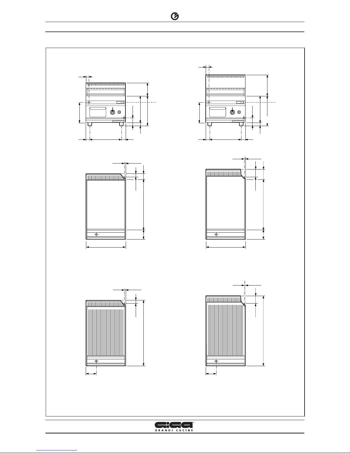
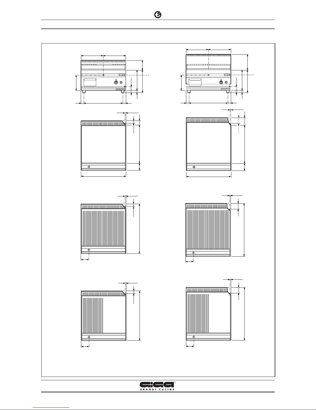
1 - DIAGRAM
009_03 - GAS FRY TOP
4 · 20
SKT1G - SKT1GC
SKT40G - SKT40GC
SKT1GR
SKT40GR
30
40 40
30
270
300
G
T
80
±1
35
±2
13.5
±1
131
320
205.5
400
52
510
93
104
G
35
±2
13.5
±1
655
TT1G - TT1GC
TT40G - TT40GC
TT1GR
TT40GR
30
40 40
30
270
300
G
T
80
±1
80
±2
13.5
±1
210
320
205.5
400
97
510
93
104
G
80
±2
13.5
±1
700
GTGas connection (1/2")
Data plate
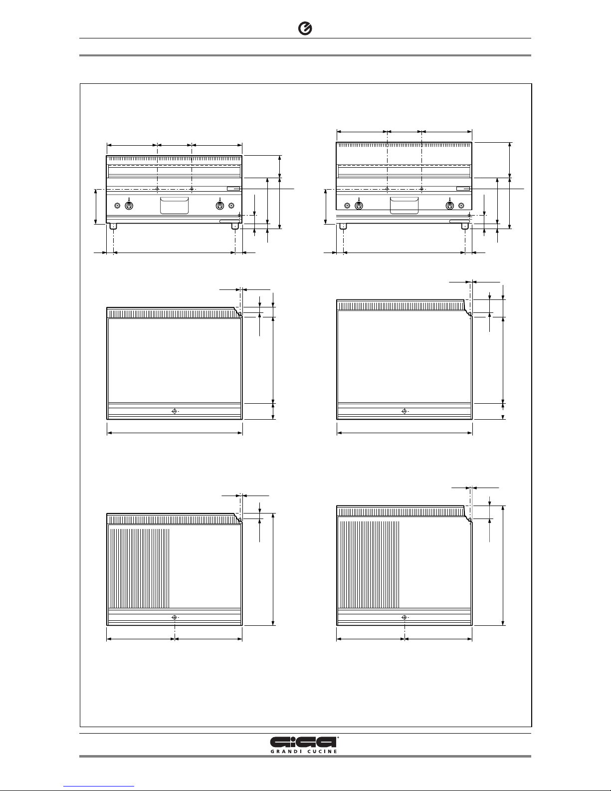
1 - DIAGRAM
009_03 - GAS FRY TOP
5 · 20
300 300
40 40
30
270
300
G
T
80
±1
80
±2
13.5
±1
210
520
205.5
600
97
510
93
104
G
80
±2
13.5
±1
700
SKT2G - SKT2G2 - SKT2GC - SKT2GC2
SKT60G - SKT60G2 - SKT60GC - SKT60GC2
300 300
40 40
30
270
300
G
T
80
±1
35
±2
13.5
±1
130
520
205.5
600
52
510
93
104
G
35
±2
13.5
±1
655
104
G
35
±2
13.5
±1
655
SKT2GLR
SKT60GLR
TT2G - TT2G2 - TT2GC - TT2GC2
TT60G - TT60G2 - TT60GC - TT60GC2
SKT2GR - SKT2GR2
SKT60GR - SKT60GR2
TT2GR - TT2GR2
TT60GR - TT60GR2
104
G
80
±2
13.5
±1
700
TT2GLR
TT60GLR
GTGas connection (1/2")
Data plate
1 - DIAGRAM
009_03 - GAS FRY TOP
6 · 20
300 200 300
40 40
30
270
300
G
T
80
±1
35
±2
13.5
±1
130
720
205.5
800
52
510
93
""
G
35
±2
13.5
±1
655
TT3G - TT3GC
TT80G - TT80GC
TT3GLR
TT80GLR
300 200 300
40 40
30
270
300
G
T
80
±1
80
±2
13.5
±1
210
720
205.5
800
97
510
93
""
G
80
±2
13.5
±1
700
SKT3G - SKT3GC
SKT80G - SKT80GC
SKT3GLR
SKT80GLR
GTGas connection (1/2")
Data plate
 Loading...