

GIGA Q2PCV, Q4PCV, Q4CFVE Instructions For Installation, Use And Maintenance Manual

IS534 ECN 3673
IT IT
IT
892-003-00
Istruzioni per installazione, uso e manutenzione
Instructions pour l’installation, l’utilisation
et
l’entretien
Instructions for installation, use
and
maintenance
Instrucciones para
la
instalación, uso y mantenimento
Aufstellungs- Bedienungs und
Wartungsanleitung
Aanwijzingen
voor
de
installatie het gebruik
en
onderhoud
01/2014
IT
FR
GB
ES
DE
NL
CUCINE VETROCERAMICA
CERAN HOBS RANGES
CUISINIERES AVEC PLAQUE VITROCERAMIQUE
COCINAS VITROCERAMICA
CERAN-KOCHFLACHEN HERDE
VITROKERAMISCHE FORNUIZEN
Q2PCV Q4PCV
Q4CFVE

IS534 ECN 3673 Page 2 of 11
INDEX
SAFETY INSTRUCTIONS
3
Warnings
INSTALLATION
3
Location of installation
Assembly
Connecting appliances
Connecting to an electricity supply
Earth and equipotential connections
PREPARING FOR OPERATION
3
Inspection of the electrical supply
Inspection of the rated thermal output
POTENTIAL TROUBLESHOOTING AND SOLUTIONS
4
Failure of radiant heating element
Difficult or unsuccessful temperature regulation of glass ceramic hob
Failure of electric oven heating element
Difficult or unsuccessful electric oven temperature regulation
REPLACING COMPONENTS WITH SPARE PARTS
4
Radiant heating element
Switch
Temperature regulation thermostat
Glass ceramic cooking hob
Electric oven heating element
Electric oven switch
Electric oven circuit breaker
Electric oven temperature regulation thermostat
Electric oven safety thermostat
INSTRUCTIONS FOR USE AND MAINTENANCE
4
Warnings
Operation
Glass ceramic cooking top
Switching on glass ceramic cooking hob
Switching off glass ceramic cooking hob
Electric oven
Switching on the electric oven
Switching off the electric oven
CARE AND MAINTENANCE
5
Cleaning glass ceramic cooking hob
Cleaning oven cooking chamber
SPARE PARTS LIST
6
EU DIRECTIVE 2002/96/EC (WEEE)
6
SERVICE INFORMATION
6
APPENDIX
7
ENG
SAFETY INSTRUCTIONS
Installation, commissioning and servicing must only be carried out by qualified personnel in compliance with
national and local regulations in force in the country of installation.
Warning
The manufacturer assumes no liability resulting from failure to follow the instructions in this booklet.
INSTALLATION
Location of installation
Technical data, dimensions, and connections are provided in the Appendix.
The appliance must be installed at least 300mm from any potential side walls, 1000mm from ceilings and
100mm from any potential back walls.
Ensure all vents are unobstructed.
If the appliance must be fitted near walls, partitions, kitchen furniture, decorative elements etc, we
recommend they are made from non-inflammable material; otherwise they should be covered with a
suitable heat resistant material. We recommend full attention is paid to fire regulations.
Install this appliance beneath an extraction canopy.
Assembly
Before connecting the appliance, all protective covers must be removed. Clean the work area and
external parts carefully with a solvent to remove any traces of glue.
Check with a spirit level. Levelling can be achieved by adjusting the legs.
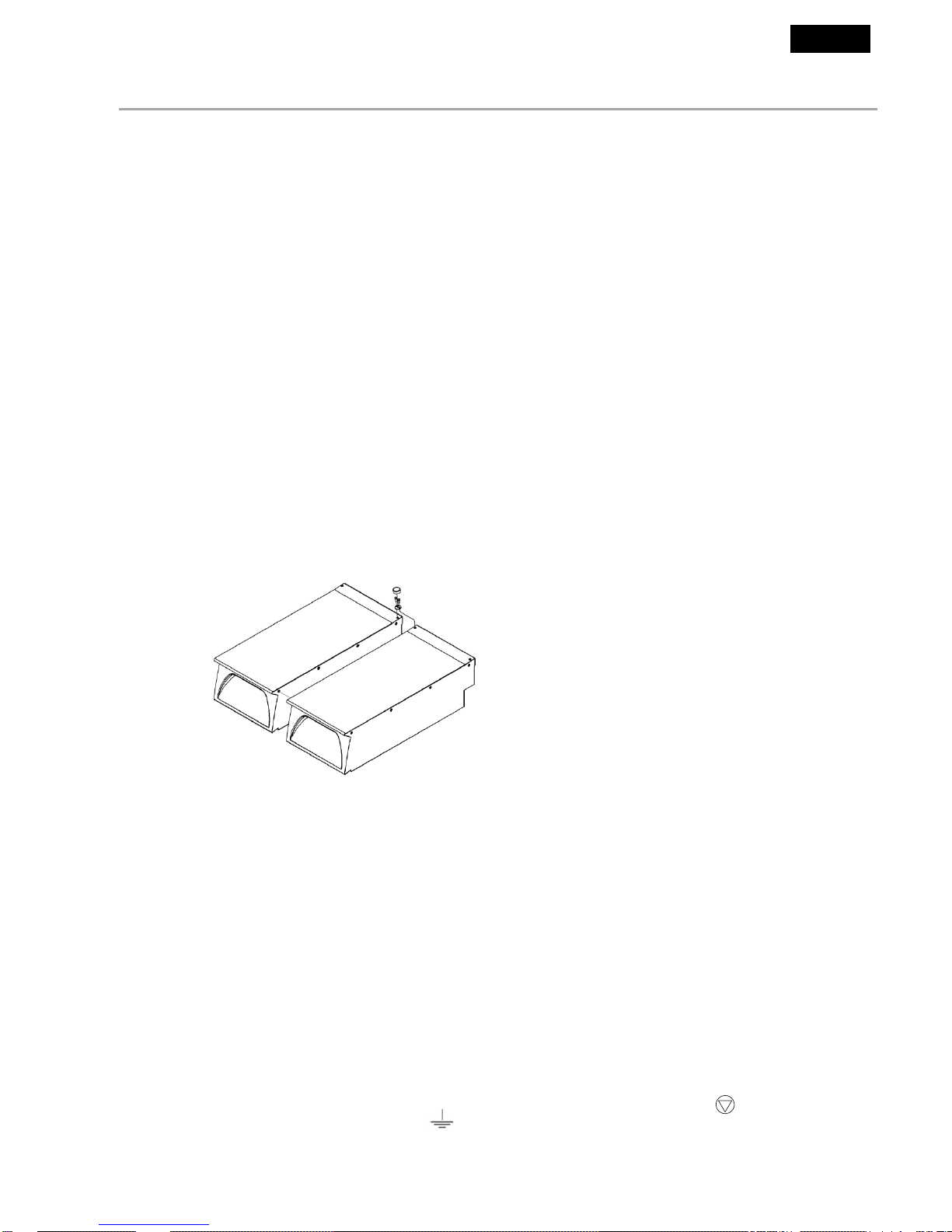
Connecting appliances (Fig 1)
Place the appliances together and adjust them to the same level using the adjustable feet.
Connect the appliances using the holes situated on the side at the front and back of the hob.
Connecting to an electricity supply
Before connecting the appliance, check that the mains voltage corresponds to the value shown on the
data plate.
The appliance must be powered by a separate electric cable which is properly specified (see Table T1)
The cable type should be at least H 07 RN-F.
Fixed wiring insulation must be protected by insulated sleeving having a temperature rating of at least 60
Deg C.
Ensure plug/socket is accessible at all times.
Connect the cable to the terminal board following the instructions on the electrical diagrams on the
appliance.
Ensure the earth cable is longer than the other cables, so that in the event that the cable clamp breaks, it
is the last lead to disconnect.
For a direct connection to a power supply, a device which guarantees disconnection from the power
supply is required, with a minimum contact separation of 3mm to ensure complete disconnection in case
of overvoltage in category III, in compliance with installation instructions.
Earth and equipotential connection
The appliance must be connected to an equipotential system – the terminal is situated near the entry point
of the electrical supply cable and is marked by the symbol
The appliance must be earthed. Connect the earth cable to the terminal near the terminal block marked
by the symbol
Fig 1
ENG

ADJUSTMENT FOR DIFFERENT VOLTAGES
To convert the appliance to a different type of voltage:
Changing the electrical connections
Remove the control panel.
Work on the terminal block following the instructions on the appliance electrical diagram.
Replace the data plate on the side of the appliance with the correct label indicating the new voltage and
electrical details.
PREPARING FOR OPERATION
Inspection of the electrical supply
Start the appliance following the operating instructions and ensure that it is working correctly.
Operate the Q4CFVE oven following the operating instructions. Check the condition of control devices
and elements, trying all modes of heating i.e.grill only, floor only etc.
In the event of a failure, the appliance is equipped with a safety thermostat that interrupts the supply. In
the event of this operating, identify and rectify the cause of the fault and restart the appliance by resetting
the thermostat manually by pushing the red button situated under the thermostat.
Inspection of the rated thermal output
When the installation, conversion and adjustment operations are complete or after maintenance, please
verify the condition of the appliance and check the rated thermal output and supply voltage
as indicated in table T1.
Attention: If the electrical supply values are not within the limits indicated in table T1, switch off the
appliance and contact your electrical supply company.
POTENTIAL TROUBLESHOOTING AND SOLUTIONS
Even during correct use of the appliance, malfunctions and breakdowns may occur. Common situations are listed
below, and checks an installer should make before contacting the technical support centre are indicated.
If after checking, the problem remains, switch the appliance off immediately and disconnect it from the power
supply. Contact the technical support centre.
Failure of hob heating elements
Check fuses.
Check the main power supply is inserted correctly.
Insufficient voltage or failed electrical connection to the appliance.
Defective switch.
Defective thermostat temperature regulation.
Defective, badly connected or burnt out heating elements.
Incorrect temperature regulation glass ceramic hob
Defective switch
Defective thermostat temperature regulation.
Defective, badly connected or burnt out heating elements.
Failure of oven heating elements
Defective switch
Defective thermostat temperature regulation.
Insufficient voltage
Safety thermostat has cut out.
Incorrect temperature regulation oven
Defective switch
Defective thermostat temperature regulation.
Defective, badly connected or burnt out heating elements
ENG
 Loading...