

041_03
Installation, operating and
maintenance instructions
01/2006
GAS FRYERS
© COPYRIGHT 2004 GIGA GRANDI CUCINE SRL
CFG15 · CFG15D
KFG15 · KFG15D
KFG20 · KFG20D
OPFG15 · OPFG20
OPFG15D · OPFG20D

Models and dimensions page 3
Data of appliances 6
Technical data 6-7
Operating instructions 8
Construction, equipment installed
and safety devices 8
Assembly 8
Location 8
Legal and technical requisites 8
Installation 8
Installation procedure 8
Gas connection 8
Gas venting 8
Commissioning the appliance 9
Before commissioning the appliance 9
Start-up 9
Testing the power rating 9
Checking input pressure 9
Checking power rating using
the volumetric method 9
Checking power rating when using
LP gas 10
Checking the pilot light 10
Checking the primary air 10
Checking the functions 10
Note for the installer page 10
Running the appliance on other types
of gas 10
Replacing the main burner nozzle 10
Replacing the pilot burner nozzle 10
Maintenance 10
Replacing parts 11
Gas valve 11
Safety thermostat 11
Burner 11
Thermocouple 11
Ignition plung 11
Electrical components 11
Using the appliance 12
Preparation for use 12
Filling the tank 12
Turning on and off 12
Lighting the pilot burner 12
Lighting the main burner 12
Turning off 12
Emptying the tank 13
Turning off in an emergency 13
What to do if something goes wrong or if
not using the appliance for a long time 13
Taking care of the appliance
frequency of maintenance 13
Warning 14
INDEX
041-03 - Gas fryers
2
041-03 - Gas fryers
3
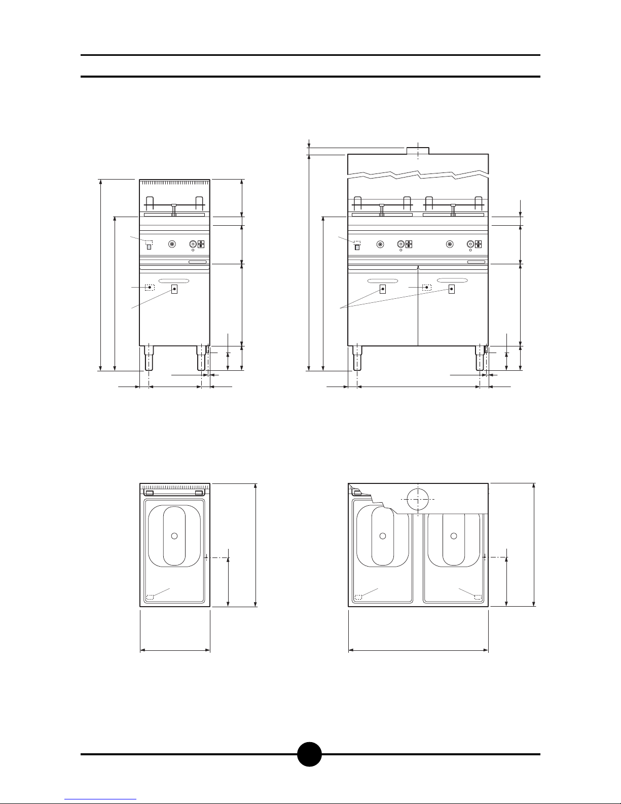
Dimensions
875
1086
52.5 52.5
13.5
1
100
2
140
465
220 21150
295
G
400
280
2
700
G
TS
50
875
1896
52.5 52.5
13.5
1
100
2
140
465
220 50
695
G
800
280
2
700
G
TS TS
T
S
TS TS
S
T
CFG15
CFG15D
G
TS
T
S
1/2” gas connector
Safety thermostat
Technical data
Oil drain
041-03 - Gas fryers
4
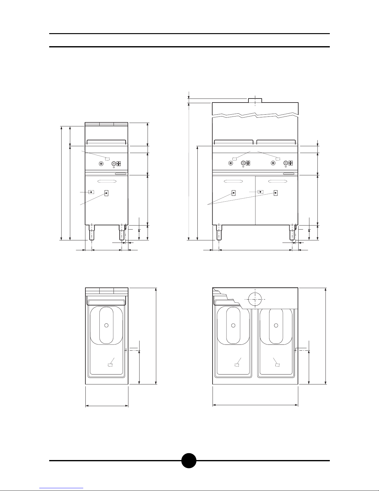
Dimensions
875 185
1060
55 55
21
100
2
140
465
210 21560
290
TS
G
400
310
2
900
G
310
2
900
G
TS TS TS
800
875
1850
55 55
21
290
TS
100
2
140
465
210 60
G
50
T
S
S
T
KFG15
KFG20
KFG15D
KFG20D
G
TS
T
S
3/4” gas connector
Safety thermostat
Technical data
Oil drain
041-03 - Gas fryers
5
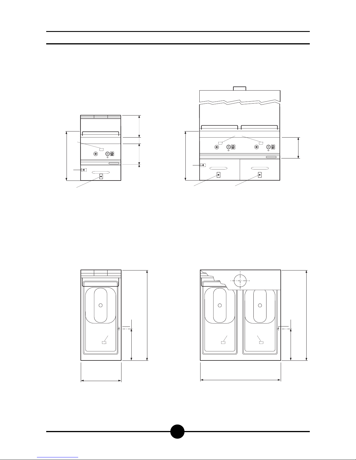
Dimensions
400
310
2
900
G
310
2
900
G
TS TS TS
800
530
TS
210
OPFG15
OPFG20
OPFG15D
OPFG20D
G
TS
T
S
3/4” gas connector
Safety thermostat
Technical data
Oil drain
210 21560
TS
530
T
T
S
S
S

041-03 - Gas fryers
6
Model
CFG15
CFG15D
KFG15
KFG15D
KFG20
KFG20D
OPFG15
OPFG15D
OPFG20
OPFG20D
Description
Gas deep fat fryer - 1 tank
Gas deep fat fryer - 2 tanks
Gas deep fat fryer - 1 tank - oil container whit filter
Gas deep fat fryer - 2 tanks - 2 oil containers whit filter
Gas deep fat fryer - 1 tank - oil container whit filter
Gas deep fat fryer - 2 tanks - 2 oil containers whit filter
Gas deep fat fryer - 1 tank
Gas deep fat fryer - 2 tanks
Gas deep fat fryer - 1 tank
Gas deep fat fryer - 2 tanks
Dimensions
(LxPxH+H1) - mm.
400 x 700 x 875 (1085)
800 x 700 x 875 (1085)
400 x 900 x 875 (1090)
800 x 900 x 875 (1090)
400 x 900 x 875 (1090)
800 x 900 x 875 (1090)
400 x 900 x 530
800 x 900 x 530
400 x 900 x 530
800 x 900 x 530
Basins Nr.
1
2
1
2
1
2
1
2
1
2
Capacity (Lt.)
15
15+15
15
15+15
20
20+20
15
15+15
20
20+20
Gas connector
1/2" ISO R228
1/2" ISO R228
3/4" ISO R228
3/4" ISO R228
3/4" ISO R228
3/4" ISO R228
3/4" ISO R228
3/4" ISO R228
3/4" ISO R228
3/4" ISO R228
N.
51BQ2905
51BQ2905
51BQ2905
51BQ2905
51BQ2905
51BQ2905
51BQ2905
51BQ2905
51BQ2905
51BQ2905
2 - CHARACTERISTICS OF THE APPLIANCES
The instructions contained in this manual apply to our Gas deep fat
fryer in the II2H3+ category (see table on page 7).
The data plate is located on the front of the appliance and on the
control panel. It contains all necessary reference data such as the
name of the manufacturer, input pressure, gas type setting, etc.
0051
TIPO/TYPE
CAT/KAT GAS/GAZ G30 G31 G20 G25
II2H3B/P P mbar 30 30 20 -
II2H3+ P mbar 30 37 20--
II2H3+ P mbar 28 37 20 -
25II2L3B/P P mbar 30 30
II2ELL3B/P P mbar 50 50 20 20
II2E+3+ P mbar 28 37 20 25
II2H3B/P P mbar 50 50 20 -
I2E P mbar - - 20 -
--II2H3B/P P mbar 30 30
II2H3+ P mbar 28 37 20 -
--
--
I3B/P P mbar 30 30
I3+ P mbar 28 37
SE FI DK CZ SK SI
IT CH PT
ES IE GB GR
NL
DE
FR BE
AT CH
LU
EE LV LT
EE LV LT
NO MT CY IS HU
CY
MOD.
MOD.
ART.
N.
N.
Qn kW
m3/h
MADE IN ITALY
Predisposto a gas: - Gas preset: - Prevu pour gaz:
Eingestelt für Gas: - Preparado para gas: -
Geschuckt voor:
V AC kW Hz
THE APPLIANCE MUST BE CONNECTED IN COMPLIANCE WITH THE LAWS IN FORCE
AND INSTALLED IN A WELL-VENTILATED ROOM. READ THE INSTRUCTION MANUALS
BEFORE INSTALLING AND USING THE APPLIANCE.
THE APPLIANCE MUST BE INSTALLED BY QUALIFIED PERSONNEL.
G30/G31 28/37 mbar
G20 20 mbar
3 - TECHNICAL DATA

041-03 - Gas fryers
7
Primary air distance “A”
Methane gas G20
Liquid gas G30/G31
TABLE 1
Model
Category
Construction type
Air necessary for combustion
Nominal thermal power
Minimum thermal power
Connection pressure
Methane gas 2H
Liquid gas 3+
Gas connection values
Methane gas 2H
Liquid gas 3+
Nozzles Ø 1/100 mm
Main burner
G20
G30/G31
(HuB = 9.45 kWh/m
3
) m3/h
(HuB = 12.87 kWh/kg) kg/h
Nominal capacity
-
Nominal capacity
-
G20
G30/31
20 mbar
28/37 mbar
II2H3+
A
m
3
/h
kW
kW
No. of nozzles, pilot burner
G20
G30/G31
2
2
0.952
0.655
2 x 160
-
2 x 110
-
Adjustable
20
2
2
1.904
1.310
4 x 160
-
4 x 110
-
Adjustable
2 x 20
2
2
1.270
0.873
2 x 185
-
2 x 120
-
Adjustable
20
2
2
2.540
1.746
4 x 185
-
4 x 120
-
Adjustable
2 x 20
CFG15
KFG15
OPFG15
A
25
9.0
-
CFG15D
KFG15D
OPFG15D
B11
50
18.0
-
KFG20
OPFG20
A
30
12.0
-
KFG20D
OPFG20D
B11
60
24.0
-

041-03 - Gas fryers
8
Construction, equipment installed and
safety devices
Robust steel frame, with 4 legs (adjustable in height).
18/10 chrome-nickel steel outer panelling and tanks.
The oil is heated by means of stainless burners (2 per
tank), built to withstand thermomechanical stress.
The pilot burner has has adjustable injector.
The combustion chamber and flues are made of electrogalvanised steel sheeting.
The temperature is regulated by a static thermal valve
which regulates ignition and extinguishing of the burners.
The deep fryers are fitted with a safety thermostat; should
the oil temperature exceed the limit value, the gas flow is
automatically cut off.
The equipment type B, if not positioned under an exhaust
hood, requires a windproof device, type MITRACF and/or
MITRAKF.
This device should be fitted as per the instructions (see
“Gas venting”).
Attention!
Activation of the safety thermostat means the appliance is not working properly; before using the appliance
again, call the service centre to carry out a careful
check of all functions.
ASSEMBLY
Location
The appliance should be installed in a well ventilated
room, and if possible under a range hood.
If possible, “A” type appliances should be placed under
an aspirator. Type “B” appliances must be fitted with an
anti-wind device.
The appliance can be installed on its own or alongside
other equipment.
If the appliance is to be installed near inflammable walls, a
minimum distance of 50 mm around the sides and back
should be allowed.
If this is impossible, take proper steps to ensure the installation is safe, such as fitting tiles or heat-reflecting material
to the walls.
Before connecting up the appliance to the gas supply,
check on the data plate that the appliance is fitted for the
type of gas available.
If not, consult paragraph “Running the appliance on other
types of gas”, page 10.
Legal and technical requisites
During assembly, the following legal and technical requisites should be adhered to:
- relevant national legislation;
- local building and fire safety regulations;
- worksheet “Technical rules for installing gas”;
- worksheet “Technical rules for LP gas”;
- worksheet “Gas installations in industrial kitchens”;
- industrial injury legislation;
- local Gas Board regulations;
- current CEI regulations.
INSTALLATION
Assembly, installation and maintenance, i.e.: assembly,
connecting the gas supply, checking power rating, transforming or adapting the appliance to run on other types of
gas, and commissioning, must all be done by contractors
authorised by the local Gas Board in accordance with local and national legislation UNI-CIG 8723-7722-7723 law
46 and circular 68 with subsequent updates.
Before doing anything else, seek advice from your Gas
Board.
Installation procedure
To level the appliance correctly, adjust the height of the
four legs.
Gas connection
The R 1/2” gas off-take for models CFG15 - CFG15D and
R 3/4” for models KFG15 - KFG15D - KFG20 - KFG20D OPFG15 - OPFG15D - OPFG20 - OPFG20D on the appliance can either be permanently fixed to the mains or
made detachable using a standard adaptor.
If flexible hose is used, it must be in stainless steel.
After completing connection, check for leaks using a special leak-detector spray.
Gas venting
For deep fryers of construction type “A”, connection to a
gas venting system is not required; for ventilation of the
premises where the appliance is installed, observe the
laws in force.
Fryers type B cannot function without the windproof device
if not positioned under an exhaust hood. Standard pipes
must be used for the flue gas outlet connection, according
to the procedures laid down by the laws in force and any
other local regulations.
Combusted gases must be evacuated:
a) by natural ascension to the outside through a chimney;
b) by mechanical extraction through a chimney to the
outside or directly outside;
c) through suction hoods.
Fit the standard anti-wind device as follows:
- Place part (A) on the appliance and fix with the relative
OPERATING INSTRUCTIONS

041-03 - Gas fryers
9
screws;
- Insert extension (B) onto the collector;
- Place part (C) on part (A) and fix with self-tapping
screws;
- Fit back element (D) onto part (A) and fix.
- connect the outlet (E) to the fume exhaust pipe.
COMMISSIONING THE APPLIANCE
Before commissioning the appliance
Before commissioning the appliance, remove the protective wrapping.
Thoroughly clean the work-surface and the outside of the
appliance using lukewarm water and detergent.
With a damp cloth eliminate all traces of the rust-proofing
applied in the workshop then dry with a clean cloth.
Start-up
Before starting the appliance up, check that its specifications (category and type of gas used) match those of
the family and group of the gas available locally.
If not, adapt the appliance to the gas family or group required (see paragraph “Running the appliance on other
types of gas” page 10).
To start the appliance up, see the instructions for regular
use.
Testing the power rating
Use the specific nozzles for the rated output (see table 1
in assembly instructions).
The following are the operating pressure tolerances to obtain the nominal power according to the agreed nozzles:
- from 15 to 22.5 mbar for gases of the second family
- from 25 to 45 mbar for gases of the third family
(propane).
The appliance will not work outside the above pressure
thresholds.
If you wish to check the nominal capacity further, you
may do so using a gas meter according to the so-called
”volumetric method”.
As a rule, however, it is sufficient to check that the correct nozzles are being used.
Checking input pressure (Fig. 2)
Input pressure should be measured using a gauge (e.g.
a gooseneck pipe, min. resolution 0.1 mbar).
Remove screw (19) from the pressure socket and connect it to the tube on the gauge; after measuring, the
screw should be retightened absolutely airtight (19).
Checking power rating using the
volumetric method
Using a gas meter and a chronometer, you can read the
volume of gas output per time unit.
The correct volume will be the value of “E” expressed in
litres per hour (It/hr) or litres per minute (It/min).
The following formula is used to calculate the value of
“E”:
Capacity should only be measured when the appliance
is at a standstill. The heat value can be obtained from
your local Gas Board.
To obtain the nominal capacity in relation to the nominal
pressure, consult table (1) (Gas Flow Setting).
Capacity
Heat value
E =
DC
A
B
E
500 mm
MIN

WARNING
It is not possible to adjust nominal capacity in advance.
Checking power rating when using LP
gas
Check that the type of nozzles used match manufacturer's specifications.
Check that the output pressure regulator installed collaterally to the plant conforms to the specifications laid
down in paragraph "Checking input pressure" page 8
(see data plate or measure the pressure).
Checking the pilot light
When correctly adjusted, the pilot light flame will completely surround the thermocouple and will not flicker; if it
does, turn the pilot adjusting screw (30 - Fig. 1 - page
11).
Checking the primary air
The devices are provided with adjustment of the primary air.
Depending on the type of gas, position the washer at measurement “A” (Fig. 1) indicated in table 1.
Checking the functions
- Start the appliance in accordance with the
instructions;
- Check the gas tubes for leaks;
- Check that the flame on the main burner lights
properly and is correctly formed;
- Check that the pilot light is correctly regulated;
- Draw up a servicing and maintenance contract.
Note for the installer
- Explain and demonstrate to the user how the machine
works according to the instructions and hand him this
manual.
- Remind the user that any structural alterations to the
room housing the appliance may affect the combustion air supply. Once the alterations have been completed, the appliance and its functions should be thoroughly checked.
Running the appliance on other types
of gas
When changing to another type of gas, e.g. from natural
to LP, or to another gas group, consult the “TECHNICAL
DATA” table to determine the correct nozzles to use.
The nozzles for the main burners for different types of
gas, marked in 100ths of mm, are in a case supplied with
the appliance.
When the appliance has been transformed or adapted,
recheck its functions as described in paragraph
"Checking the functions" page 10.
Replacing the main burner nozzle
(Fig. 1)
To change the nozzle (28), remove the air adjustment (27)
loosening the screw (33), unscrew it from the nozzle holder using a 12 mm wrench and replace with a new one
(see “TECHNICAL DATA” table).
After fitting the nozzle, reset primary air distance “A”
(see “TECHNICAL DATA” table).
Adjusting the pilot burner (Fig. 1)
The pilot burner is readily accessible when the door is
opened.
Unscrew nut (34) and using a screwdriver adjust the bypass. For use with LPG, the adjusting screw must be fully screwed down. Tighten the nut, making sure the gasket has been inserted.
MAINTENANCE
Attention!
Before carrying out any maintenance or repair work,
disconnect the appliance from the mains.
The following maintenance programme should be carried out at least once a year:
- Check that all the safety and setting devices are
working properly;
- Check that the burners are working properly with regard to:
- ignition
- combustion safety;
- Check the functions of the appliance as described in
paragraph "Checking the functions", page 10;
- Check the gas venting path (make sure the gas is correctly evacuated).
041-03 - Gas fryers
10
1
2
19
2

041-03 - Gas fryers
11
REPLACING PARTS
All parts must be replaced by authorised technicians
only!
To replace the following parts, remove the control panel
(after unscrewing its fixing screws). It is advisable to
empty the tank.
Gas valve (1 - Fig. 2)
Unscrew the gas pipes and thermocouple. Unscrew the
screws (2). Remove the bulb from the holder on the tank.
The valve may now be removed and replaced with a new
one.
Replace and screw down all parts in the correct order.
Safety thermostat (11 - Fig. 3)
Unscrew the lock nut and the nut fixing the bulb in the
tank, disconnect and insert the new part.
Burner (Fig. 1)
Unscrew nozzle (28) and nut (29). Loosen the screws (26)
fixing the burner to the chamber. Replace the burner.
Thermocouple (38 - Fig. 1)
Unscrew the nipple fixing the thermocouple to the valve,
loosen the 2 screws (25) on the pilot burner and replace
the thermocouple. To simplify the operation (and all those
concerning the pilot burner), screws (31) may be removed
and the pilot burner moved to a more accessible position.
Ignition plug (32 - Fig. 1)
Disconnect the ignition wire, unscrew two fastening
screws (25) and insert a new plug. To simplify the operation, see the above-mentioned position.
WARNING
Everytime a replacement involving gas input parts is
made, recheck all functions and test for leakage.
A
29
27
33
33
27
28
26
25
32
38
37
30
34
31
1

041-03 - Gas fryers
12
10
13
12
11
14
15
3
Warning!
- Beware of inexpert handling!
- Old and dirty oil or frying fat can represent a real fire
hazard; make sure only new oil or frying fat are used
each time you start frying.
- The food you intend to fry should always be dry; wet
food causes the oil to foam and overflow.
- Frying excessively large quantities of food at a time
also causes the oil to foam; never exceed 2 kg.
- If the level of oil in the bath falls below the low level
mark stamped on it, the risk of fire will increase.
- Never leave the appliance on without any oil in it. The
lid delivered with the appliance should always be kept
within easy reach. In case of fire, it should be used to
douse the flames.
Preparation for use
Before frying for the first time, it is advisable to thoroughly
clean the appliance and above all the tank (see paragraph
"Cleaning and maintenance").
Filling the tank
Check that the oil drainage outlet is closed. Fill the tank
up to the maximum level mark with frying oil or liquid fat.
Turning on and off (Fig. 3)
Turn on gas supply.
Lighting the pilot burner
Press the button (14) and as the same time the piezoelectric lighter (12) to light the pilot flame, which can be seen
through hole 10 after opening the door at the bottom. Hold
the button down for at least 20/25 seconds. If the flame
goes out when you release the button, repeat the operation.
Lighting the main burner
To light the main burner turn the knob (13) on the thermostat
to the desired temperature considering that the 8 positions
correspond to approximately the following temperatures:
Position degrees °C.
1 120
2 130
3 140
4 150
5 160
6 170
7 180
8
190
Turning off
To turn off the main burner turn knob (13) to the spark position , so that only the pilot flame remains on.
To turn if off altogether, press the off button (15).
USING THE APPLIANCE

041-03 - Gas fryers
13
Emptying the tank
When emptying, check that you have a container large
enough to collect all the oil in the tank.
The container should be placed correctly under the drain
tap.
It is advisable to filter frying oil and fat daily and to change completely when necessary.
Open the drainage tap; when the tank is empty, close the
tap before removing the container.
Turning off in an emergency
In the case of malfunctioning, turn off the appliance and
turn off the gas and electric supply.
What to do in the case of malfunctioning or if the appliance is not to be
used for a long period
When the appliance is not to be used for a long time,
clean thoroughly and turn off both the gas and electric
supply. In the case of malfunctioning or failure, turn off
the gas supply and disconnect from the mains. Call the
service centre.
TAKING CARE OF THE APPLIANCE
FREQUENCY OF MAINTENANCE
Warning!
Never clean the appliance with jets of water, whether
direct or pressurised.
Allow the machine to cool down before cleaning
Giving the appliance a thorough clean every day (after turning it off) will keep it in perfect working order and make it
last longer.
All steel parts should be cleaned with water and a detergent, using a damp cloth; do not use abrasive substances
or corroding detergents.
Do not use steel wool, which could leave traces of rust.
For the same reason, avoid touching the appliance with
anything made of iron.
Do not clean any parts of the appliance other than the grilling plate with emery or sandpaper. If absolutely necessary, you may use powdered pumice stone.
If the appliance is extremely dirty, use a synthetic sponge
such as Scotchbrite.
After cleaning the appliance, rinse with clean water and
dry with a clean cloth.
All maintenance work must be carried out by qualified personnel only.
Have the appliance checked at least once a year; we
strongly recommend that you stipulate a servicing and
maintenance contract with your supplier.

041-03 - Gas fryers
14
WARNING
DUE TO ITS POLICY OF CONTINUAL PRODUCT IMPROVEMENT, THE MANUFACTURER RESERVES THE RIGHT
TO MAKE ANY CHANGES DEEMED NECESSARY.
THE MANUFACTURER CANNOT BE HELD RESPONSIBLE IF THE INSTRUCTIONS CONTAINED IN THIS MANUAL ARE NOT OBSERVED.
GIGA GRANDI CUCINE S.r.l. - Via Pisana, 336 - Loc. Olmo - 50018 SCANDICCI (FI) - ITALY Tel. +39 055 722 33 (11 linee r.a.) - Fax +39 055 7310 056 - www.gigagrandicucine.it -
info@gigagrandidicucine.it
 Loading...