

GIGA IF1E4, IF4E, IF2E6, IF6E Installation, Operating And Maintenance Instructions
505_03
Installation, operating and
maintenance instructions
11/2006
© COPYRIGHT 2004 GIGA GRANDI CUCINE SRL
ELECTRIC FRYER
IF1E4 · IF4E
IF2E6 · IF6E
Validity from serial number
15210851
CHARACTERISTICS
505_03 - ELECTRIC FRYER
2 · 16
11/2006
Supplied by:
Date:
Customer Service:
FAX
e-mail
INDEX
505_03 - ELECTRIC FRYER
3 · 16
11/2006
1 Diagram 4
2 Features of the appliances 5
3 Technical data 5
4 Installation instructions 6
4.1 Safety rules 6
4.2 Structure, framework and safety devices of the appliances 6
4.3 Assembly 6
4.3.1 Installation premises 6
4.3.2 Statutory regulations and technical requirements 6
4.3.3 Installation 6
4.3.4 Wiring 6
4.3.5 Equipotential 6
4.4 Preparing for installation 6
5 Operation preparation 7
5.1 Preparation and Start-up 7
5.1.1 Start-up 7
5.1.2 Operator training 7
5.2 Maintenance 7
5.3 Ignition 11
5.3.1 Emptying the vessel 11
5.3 Cleaning and taking care of the machine 11
6 Instructions for use 12
6.1 Safety, cleaning and repair rules 12
6.2 Turning the appliance off in case of breakdown 12
6.2.1 What to do in case of failure or prolonged period of
disuse 12
6.3 Appliance care and frequency of maintenance 12
6.4 Recommendations for handling stainless steel industrial
kitchens 12
6.4.1 Useful information on stainless steel 12
6.4.2 Warnings and advice for maintenance of stainless steel
appliances 13
6.4.3 WEEE Directive 13
7 Appendix: Electrical diagrams 14-15
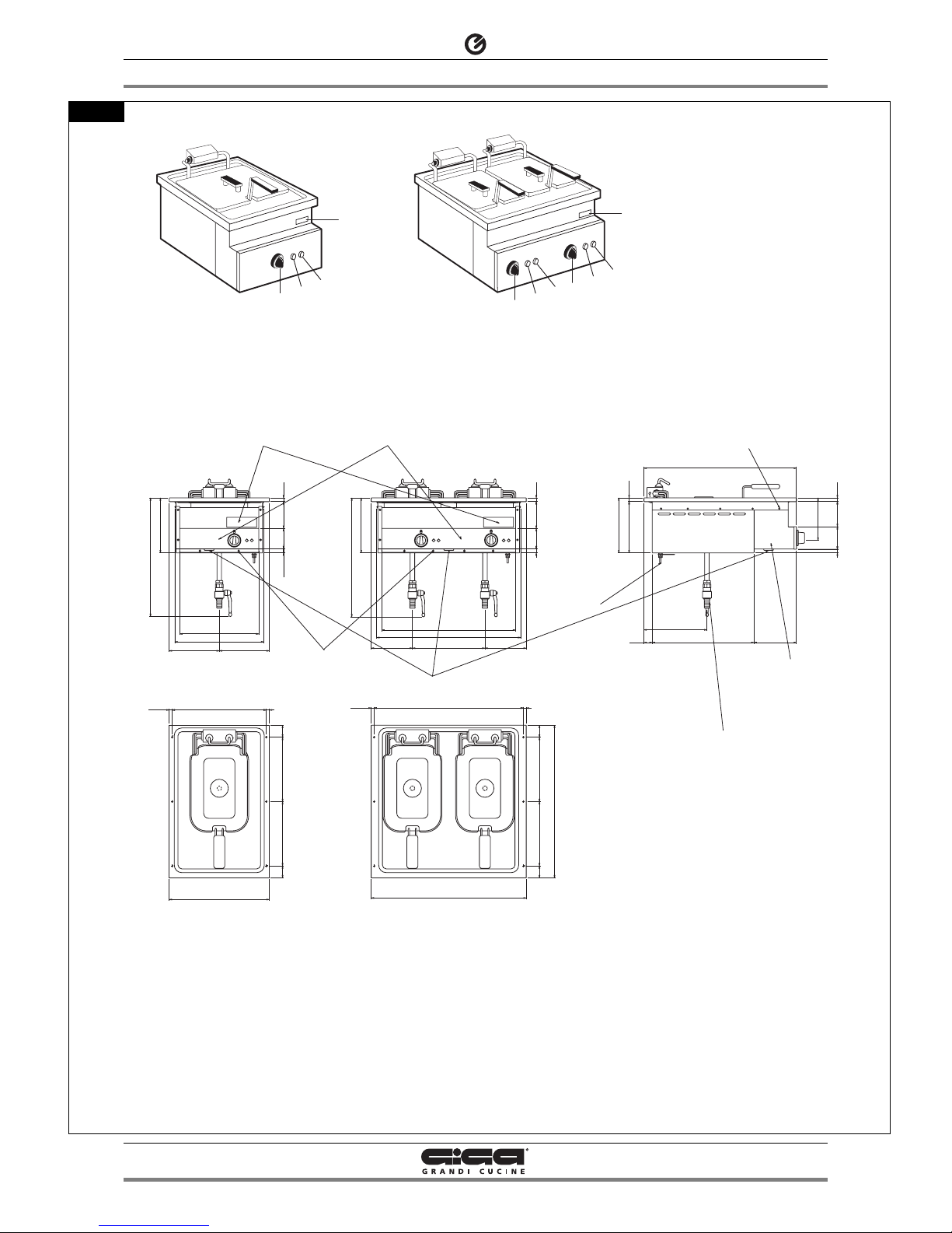
1 - DIAGRAM
505_03 - ELECTRIC FRYER
4 · 16
11/2006
IF2E6
IF2E6
IF6E
IF6E
IF1E4
IF1E4
IF4E
IF4E
610
610
48
48
48
48
257
257
257
257
165
165
290
290
165
165
200
200
200
200
252
252
15
15
E
E
204.5
204.5
219.5
219.5
170
170
33
33
407
407
90
90
F
F
A
A
14.5
14.5
170
170
100
100
15
15
610
610
90
90
100
100
14.5
14.5
11.5
11.5
11.5
11.5
597
597
536
536
756
756
620
620
356
356
316
316
377
377
11.5
11.5
257
257
48
48
90
90
14.5
14.5
100
100
48
48
257
257
A
A
219.5
219.5
15
15
15
15
D
D
400
400
475
475
-
-
MAX
MAX
475
475
-
-
MAX
MAX
1111.5
.5
219.
219.
5
5
T
T
C
B
T
G
T
C
B
G
C
B
G
IF1E4
IF1E4
IF4E
IF4E
IF2E6
IF2E6
IF6E
IF6E
V
V
V
V
A
B
C
D
E
F
G
T
V
Terminal board
Green indicator light (tension)
Yellow indicator light (resistance)
Cable input
Equipotenital
Oil drainpipe
Knob
Data plate
Screw
Fig. 1
2 - CHARACTERISTICS OF THE APPLIANCES
3 - TECHNICAL DATA
505_03 - ELECTRIC FRYER
5 · 16
11/2006
These appliances are used for professional purposes. Installation,
repair and use must be carried out by expert personnel.
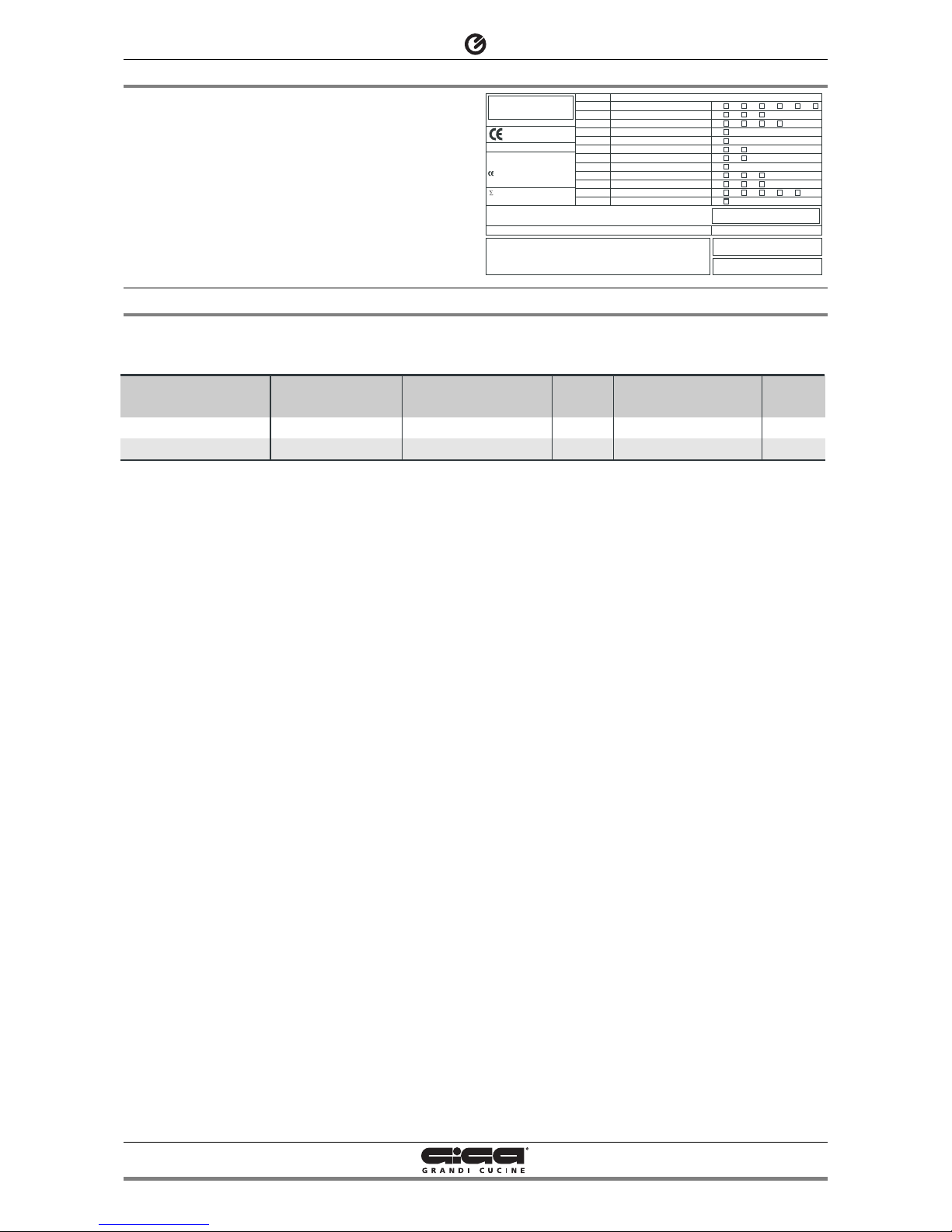
The data plate (T) is located on the appliance and contains all the
data needed for installation.
TIPO/TYPE
CAT/KAT GAS/GAZ G30 G31 G20 G25
II2H3B/P P mbar 30 30 20 II2H3+ P mbar 30 37 20-II2H3+ P mbar 28 37 20 -
25II2L3B/P P mbar 30 30
II2ELL3B/P P mbar 50 50 20 20
II2E+3+ P mbar 28 37 20 25
II2H3B/P P mbar 50 50 20 I2E P mbar - - 20 -
--II2H3B/P P mbar 30 30
II2H3+ P mbar 28 37 20 -
--
--
I3B/P P mbar 30 30
I3+ P mbar 28 37
SE FI DK CZ SK SI
IT CH PT
ES IE GB GR
NL
DE
FR BE
AT CH
LU
EE LV LT
EE LV LT
NO MT CY IS HU
CY
MOD.
MOD.
ART.
N.
N.
Qn kW
m3/h
MADE IN ITALY
Predisposto a gas: - Gas preset: - Prevu pour gaz:
Eingestelt für Gas: - Preparado para gas: -
Geschuckt voor:
V AC kW Hz
THE APPLIANCE MUST BE CONNECTED IN COMPLIANCE WITH THE LAWS IN FORCE
AND INSTALLED IN A WELL-VENTILATED ROOM. READ THE INSTRUCTION MANUALS
BEFORE INSTALLING AND USING THE APPLIANCE.
THE APPLIANCE MUST BE INSTALLED BY QUALIFIED PERSONNEL.
Model
IF1E4 - IF4E
IF2E6 - IF6E
Dimensions in mm.
(LxPxH)
400 x 610 x 220
600 x 610 x 220
Voltage rating
400 V 3N or 230 V 3
400 V 3N or 230 V 3
Power
7.5 kW
15.0 kW
Lead wire / Section
5 x 1.5 mm2 or 4 x 2.5 mm
2
5 x 2.5 mm2 or 4 x 6 mm
2
 Loading...