

GIGA I6FZP, I2FZP, I4FZP Instructions For Installation, Use And Maintenance Manual

502_03
Instructions for installation,
use and maintenance
09/2015
© COPYRIGHT 2004 GIGA GRANDI CUCINE SRL
GAS KITCHENS
I2FZP
I4FZP
I6FZP
CHARACTERISTICS
502_03 - GAS KITCHENS
2 · 16
Supplied by:
Date:
Customer Service:
FAX
e-mail

INDEX
502_03 - GAS KITCHENS
3 · 16
1 Diagram 4
2 Features of the appliances 5
3 Technical data 5
4 Installation instructions 6
4.1 Safety rules 6
4.2 Structure, framework and safety devices of the appliances 6
4.2.1 Cooking zone 6
4.3 Assembly 6
4.3.1 Installation premises 6
4.3.2 Statutory regulations and technical requirements 6
4.3.3 Installation 6
4.3.4 Gas connection 6
4.3.5 Smoke extraction 6
4.3.6 Equipotential 6
4.4 Preparing for installation 7
5 Operation preparation 7
5.1 Preparation and Start-up 7
5.1.1 Start-up 7
5.1.2 Check of power 7
5.1.3 Checking the input pressure 11
5.1.4 Power check with volumetric method 11
5.1.5 Power check for operation with liquid gas 11
5.1.6 Check of pilot flame 11
5.1.7 Checking the primary air 11
5.1.8 Operation Control 12
5.1.9 Operator training 12
5.1.10 Conversion and adjustment 12
5.1.11 Replacement of burner nozzles 12
5.1.12 Setting reduced capacity power 12
5.1.13 Replacement of pilot nozzle (open flames) 12
5.2 Maintenance 12
5.3 Replacing parts 12
5.3.1 Gas valve (open flames) 12
5.3.2 Thermocouple (open flames) 12
6 Instructions for use 13
6.1 Safety, cleaning and repair rules 13
6.2 Start-up 13
6.2.1 Lighting and disconnecting open flame burner 13
Shutdown 13
6.3 Turning the appliance off in case of breakdown 13
6.3.1 What to do in case of failure or prolonged period of
disuse 13
6.4 Appliance care and frequency of maintenance 13
6.5 Recommendations for handling stainless steel industrial
kitchens 14
6.5.1 Useful information on stainless steel 14
6.5.2 Warnings and advice for maintenance of stainless steel
appliances 14
6.5.3 WEEE Directive 15
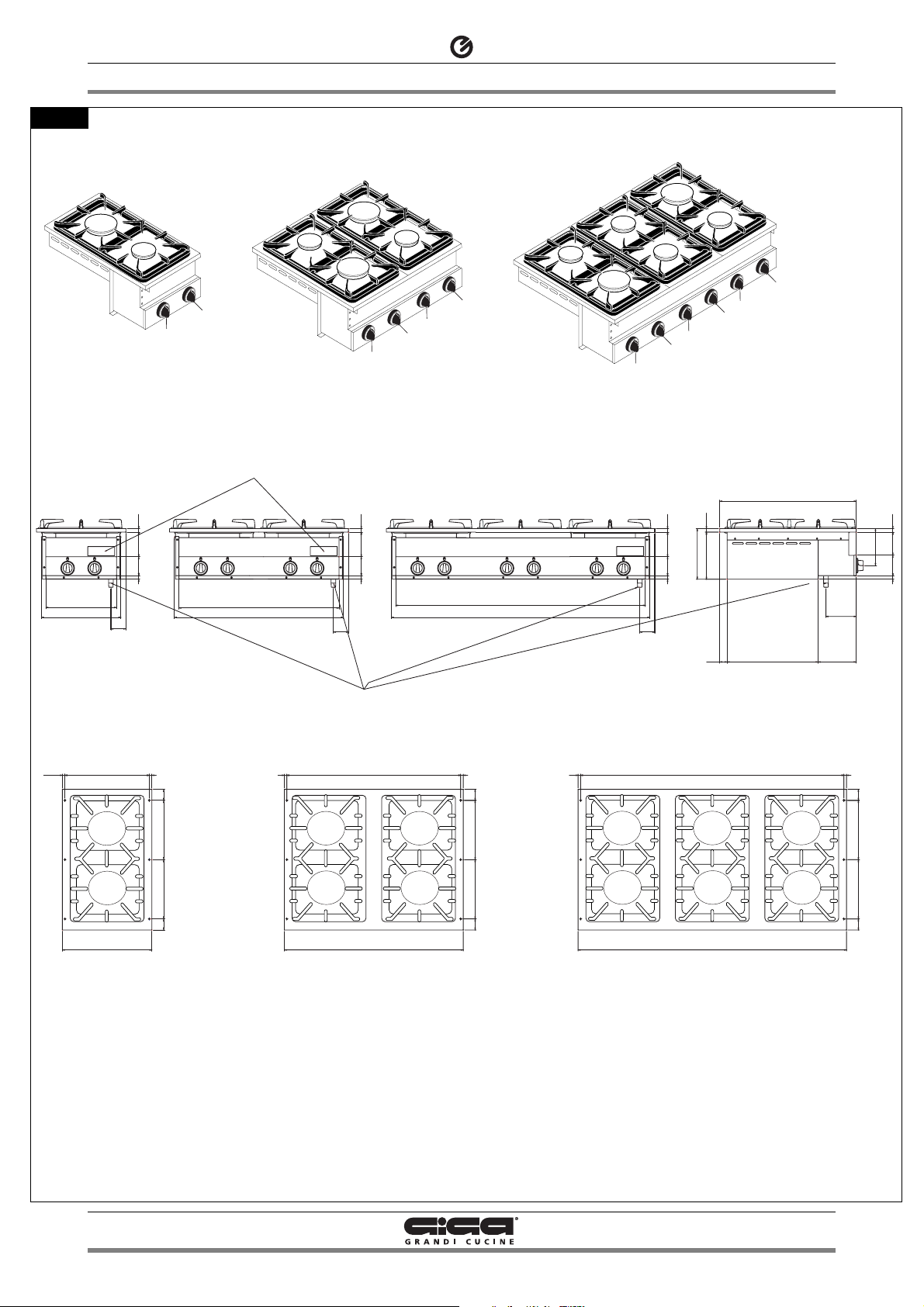
1 - DIAGRAM
502_03 - GAS KITCHENS
4 · 16
B
T
G
Knob
Data plate
Gas connection 1/2"
Fig. 1
B
B
B
B
B
B
B
B
B
B
B
B
I6FZPI6FZPI4FZPI4FZPI2FZPI2FZP
TT
610610
1515
1515
1515
1515
1515
11.511.5
316316
356356
377377
7.8
kW
4.0
kW
400400
100100
9090
14.514.5
6767
716716
755755
100100
9090
14.514.5
6767
755755
11161116
100100
219.5219.5
9090
204.5204.5
14.514.5
135135
6767
3333
407407
170170
160160
100100
9090
14.514.5
GG
48484848
257257
257257
11.511.5
4.0
kW
7.8
kW
777777
800800
7.8
kW
4.0
kW
4848
257257
257257
4848
11.511.5
4.0
kW
7.8
kW
11771177
4.0
kW
4.0
kW
12001200
7.8
kW
4.0
kW
4848
257257
257257
4848
I6FZPI6FZPI4FZPI4FZPI2FZPI2FZP
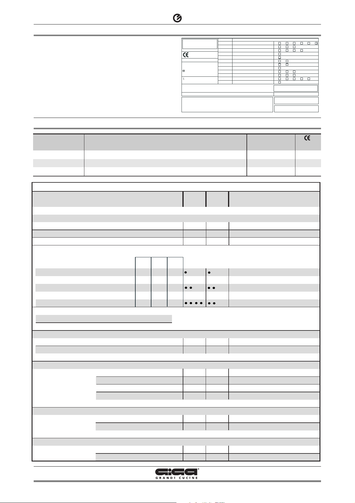
2 - CHARACTERISTICS OF THE APPLIANCES
3 - TECHNICAL DATA
502_03 - GAS KITCHENS
5 · 16
These appliances are used for professional purposes. Installation,
repair and use must be carried out by expert personnel.
These instructions for installation are for our gas kitchens set up for
the category in the table on page 5. The data plate is located on the
front part of the appliance (on the control panel).
Primary air distance “A”
Methane gas G20
Liquid gas G30/G31
TABLE 1
Category
Construction type
Air necessary for combustion
Nominal thermal power
Minimum thermal power
Overall thermal power (gas)
Connection pressure
Methane gas 2H
Liquid gas 3+
Nozzles Ø 1/100 mm
Main burner
G20
G30/G31
(HuB = 9.45 kWh/m3) in m3/h
(HuB = 12.87 kWh/kg) in kg/h
Nominal thermal power
Minimal thermal capacity
Nominal thermal power
Minimal thermal capacity
G20
G30/31
20 mbar
28/37 mbar
12.2
24.4
32.8
kW
kW
kW
II2H3+
A
m
3
/h
kW
kW
No. of nozzles, pilot burner
G20
G30/G31
7
Open
X
Ø 100
8
4.0
1.2
0.423
0.313
145
Adjustable
100
45
27
19
15
Open
Z
Ø 120
14
7.8
2.9
0.825
0.611
200
Adjustable
135
75
27
19
1,29
2,58
3,47
-
-
-
-
0,95
1,91
2,57
Hour consumption
G20
m3/h
G25
m3/h
G30/G31
kg/h
I2FZP
I4FZP
I6FZP
Model
Gas connection values
Methane gas 2H
Liquid gas 3+
Model
I2FZP
I4FZP
I6FZP
Description
2 burners with pilot flame
4 burners with pilot flame
6 burners with pilot flame
Dimensions in mm.
(LxPxH)
400 x 610 x 220
800 x 610 x 220
1200 x 610 x 220
N.
51BQ2896
51BQ2896
51BQ2896
TIPO/TYPE
MOD.
ART.
N.
MOD.
V AC kW Hz
THE APPLIANCE MUST BE CONNECTED IN COMPLIANCE WITH THE LAWS IN FORCE
AND INSTALLED IN A WELL-VENTILATED ROOM. READ THE INSTRUCTION MANUALS
BEFORE INSTALLING AND USING THE APPLIANCE.
THE APPLIANCE MUST BE INSTALLED BY QUALIFIED PERSONNEL.
N.
Qn kW
CAT/KAT GAS/GAZ G30 G31 G20 G25
II2H3B/P P mbar 30 30 20 II2H3+ P mbar 30 37 20-II2H3+ P mbar 28 37 20 -
0051
II2ELL3B/P P mbar 50 50 20 20
II2E+3+ P mbar 28 37 20 25
II2H3B/P P mbar 50 50 20 I2E P mbar - - 20 -
II2H3+ P mbar 28 37 20 -
m3/h
I3B/P P mbar 30 30
I3+ P mbar 28 37
Eingestelt für Gas: - Preparado para gas: -
25II2L3B/P P mbar 30 30
--II2H3B/P P mbar 30 30
--
Predisposto a gas: - Gas preset: - Prevu pour gaz:
--
Geschuckt voor:
SE FI DK CZ SK SI
IT CH PT
ES IE GB GR
NL
DE
FR BE
AT CH
LU
EE LV LT
EE LV LT
NO MT CY IS HU
CY
MADE IN ITALY
G30/G31 28/37 mbar
G20 20 mbar
 Loading...