

GIGA K2F, K4F, K4FS, K8F, K4FFE Instructions For Installation, Use And Maintenance Manual
...
011_03
Instructions for installation,
use and maintenance
07/2009
GAS KITCHENS
K2F · K4F · K4FS · K6F · K8F
K4FFE · K4FSFE · K6FFE · K8FFE
K4FSFCE
K4FSFCG
K4FFG · K4FSFG · K6FFG · K8FFG
K6FFGA
B4F · B6F · B8F
OP2F · OP4F · OP6F · OP8F
© COPYRIGHT 2004 GIGA GRANDI CUCINE SRL
CHARACTERISTICS
011_03 - GAS KITCHENS
2 · 22
07/2009
Supplied by:
Date:
Customer Service:
FAX
e-mail
011_03 - GAS KITCHENS
3 · 22
07/2009
1 Diagram 4
2 Features of the appliances 7
3 Technical data 7-8
4 Installation instructions 9
4.1 Safety rules 9
4.2 Structure, equipment and safety devices of the appliances 9
4.2.1 Cooking zone 9
4.2.2 Oven 9
Gas version GN 2/1 and MAXI 9
Gas version GN 1/1 ventilated 9
Electric version GN 2/1 9
Electric version GN 1/1 ventilated 9
4.2.3 Neutral cabinet 9
4.3 Assembly 9
4.3.1 Installation premises 9
4.3.2 Statutory regulations and technical requirements 10
4.3.3 Installation 10
4.3.4 Installation operations 10
4.3.5 Gas connection 10
4.3.6 Smoke extraction 10
4.3.7 Electrical connection 10
4.3.8 Equipotential 10
5 Operation preparation 10
5.1 Preparation and Start-up 10
5.1.1 Start-up 10
5.1.2 Check of power 10
5.1.3 Checking the input pressure 11
5.1.4 Power check with volumetric method 11
5.1.5 Power check for operation with liquid gas 11
5.1.6 Check of pilot flame 11
5.1.7 Checking the primary air 11
5.1.8 Operation Control 13
5.1.9 Operator training 13
5.1.10 Conversion and adjustment 13
5.1.11 Replacement of burner nozzles 13
5.1.12 Setting reduced capacity power 13
5.1.13 Replacement of pilot nozzle (open flames) 13
5.1.14 Replacement of pilot nozzle (gas oven GN 2/1) 13
5.1.15 Replacement of pilot nozzle (gas oven MAXI) 13
5.1.16 Replacement of nozzle of gas ovens GN 1/1 and MAXI 13
5.1.17 Replacement of burner nozzle (gas oven) 13
5.2 Maintenance 13
5.3 Replacing parts 14
5.3.1 Gas valve (open flames) 14
5.3.2 Thermocouple (open flames) 14
5.3.3 Plug (gas oven) 14
5.3.4 Gas valve (gas oven) 14
5.3.5 Thermocouple (gas oven) 14
5.3.6 Main burner (gas oven) 14
5.3.7 Heating elements (electric oven GN 1/1) 14
5.3.8 Heating elements (electric oven GN 2/1) 14
5.3.9 Fan for electric and gas ovens GN 1/1 14
6 Instructions for use 14
6.1 Safety, cleaning and repair rules 14
6.2 Start-up 15
6.2.1 Lighting and disconnecting open flame burner 15
6.3 Lighting and shutting down a gas oven 15
6.3.1 Lighting the pilot (gas oven GN 1/1) 15
6.3.2 Lighting the pilot (gas oven GN 2/1 and MAXI) 15
6.3.3 Lighting the main burner and temperature adjustment
(gas ovens GN 1/1) 16
Shutdown 16
6.3.4 Lighting the main burner and temperature adjustment
in gas oven GN 1/1 16
Shutdown 16
6.4 Lighting and shutdown of electric oven GN 1/1 16
6.5 Lighting and shutdown of electric oven GN 2/1 16
6.6 Turning the appliance off in case of breakdown 16
6.6.1 What to do in case of failure or prolonged period
of disuse 17
6.7 Appliance care and frequency of maintenance 17
6.8 Recommendations for handling stainless steel
industrial kitchens 17
6.8.1 Useful information on stainless steel 17
6.8.2 Warnings and advice for maintenance of stainless steel
appliances 17
6.8.3 WEEE Directive 18
7 Appendix: Electrical diagrams 19-21
INDEX
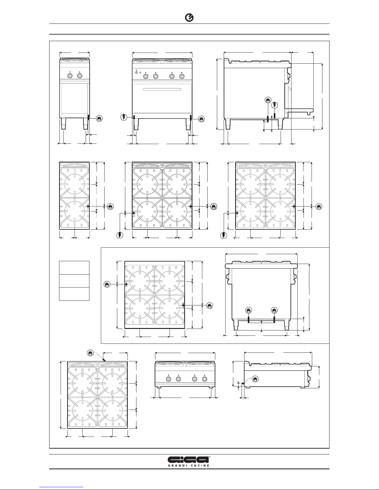
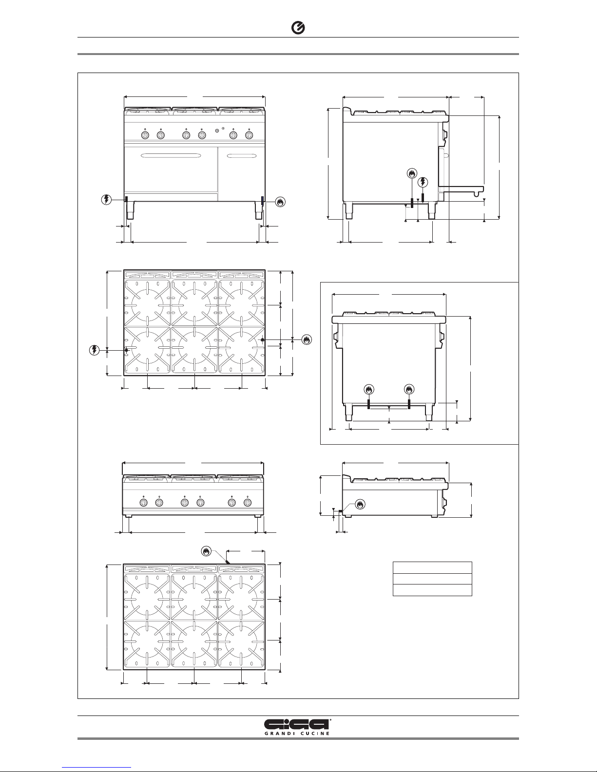
1 - DIAGRAM
011_03 - GAS KITCHENS
4 · 22
07/2009
4.3 kW
Ø 80 mm
6.4 kW
Ø 100 mm
8.3 kW
Ø 120 mm
142
900
900
706
100
3/4" 3/4"
142
800
694
53
53
35
270
900
55
340
200
200 400
900
255
350
295
6.4
kW
8.3
kW
8.3
kW
4.3
kW
140
255
200 200
295
350
310
590
6.4
kW
4.3
kW
3/4"
100
150
142
900
52
300900
706
150
3/4"
970
400
53
21
53
294
3/4"
B4F
OP4F
K2F
K2F - OP2F
B4F
OP4F
K4FFG
K4FFE
K4F
K4FFG - K4FFE
K4FS - K4FSFCG
K4FSFG - K4FSFCE - K4FSFE
800
694
53
53
21
21
3/4"
220
680
255
350
295
310
590
6.4
kW
8.3
kW
8.3
kW
4.3
kW
3/4"
220
680
255
350
295
310
590
3/4"
200200 400
200
200 400
220
680
255
350
295
310
590
8.3
kW
8.3
kW
8.3
kW
3/4"
8.3
kW
200
200 400
590
310
275
350
275
310
590
3/4"
3/4"
6.4
kW
8.3
kW
8.3
kW
4.3
kW
150
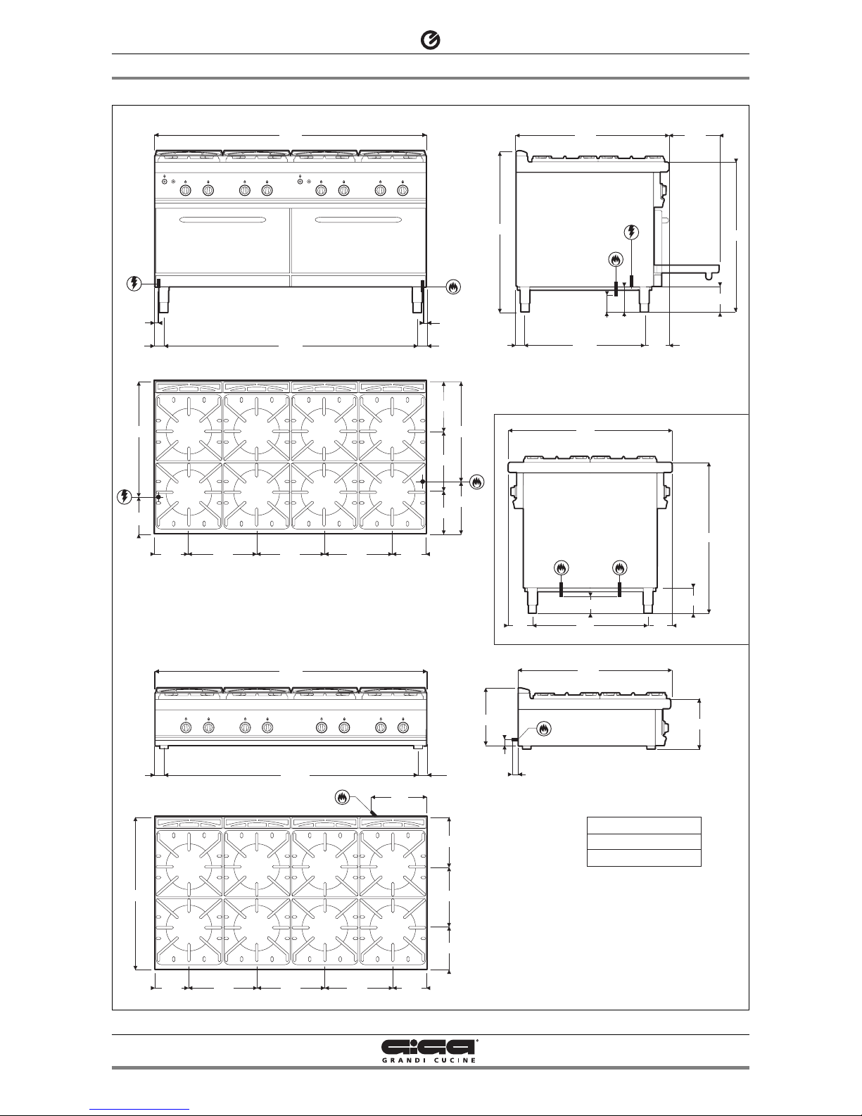
1 - DIAGRAM
011_03 - GAS KITCHENS
5 · 22
07/2009
3/4"
1200
5353 1094
21 21
100
150
142
900
52
300900
706
150
3/4"
970
4.3 kW Ø 80 mm
6.4 kW Ø 100 mm
8.3 kW Ø 120 mm
1200
5353 1094
142
900
900
706
150
100
3/4"
3/4"
142
270
900
35
55
340
900
255
296
350
200 200400400
6.4
kW
8.3
kW
8.3
kW
4.3
kW
6.4
kW
4.3
kW
140
680
255
296
350
310
590
200 200400400
3/4"
6.4
kW
8.3
kW
8.3
kW
4.3
kW
6.4
kW
4.3
kW
220
B6F
OP6F
OP6F
K6FFG
K6FFE
K6FFGA
K6F
K6FFG - K6FFE
K6FFGA
1 - DIAGRAM
011_03 - GAS KITCHENS
6 · 22
07/2009
100
150
142
900
52
300900
706
150
3/4"
970
3/4"
220
680
255
296
350
310
590
200 200400 400 400
6.4
kW
8.3
kW
8.3
kW
4.3
kW
6.4
kW
4.3
kW
6.4
kW
8.3
kW
53
1600
53 1494
900
255
296
350
200 200400 400 400
6.4
kW
8.3
kW
8.3
kW
4.3
kW
6.4
kW
4.3
kW
6.4
kW
8.3
k W
140
270
900
35
55
340
142
900
900
706
150
100
3/4"3/4"
142
1600
21 21
3/4"
5353 1494
4.3 kW Ø 80 mm
6.4 kW Ø 100 mm
8.3 kW Ø 120 mm
B8F
OP8F
OP8F
K8FFG
K8FFE
K8F
K8FFG - K8FFE
3 - TECHNICAL DATA
011_03 - GAS KITCHENS
7 · 22
07/2009
These appliances are used for professional purposes. Installation,
repair and use must be carried out by expert personnel.
These instructions for installation are for our gas kitchens set up for
the category in the table on page 8.
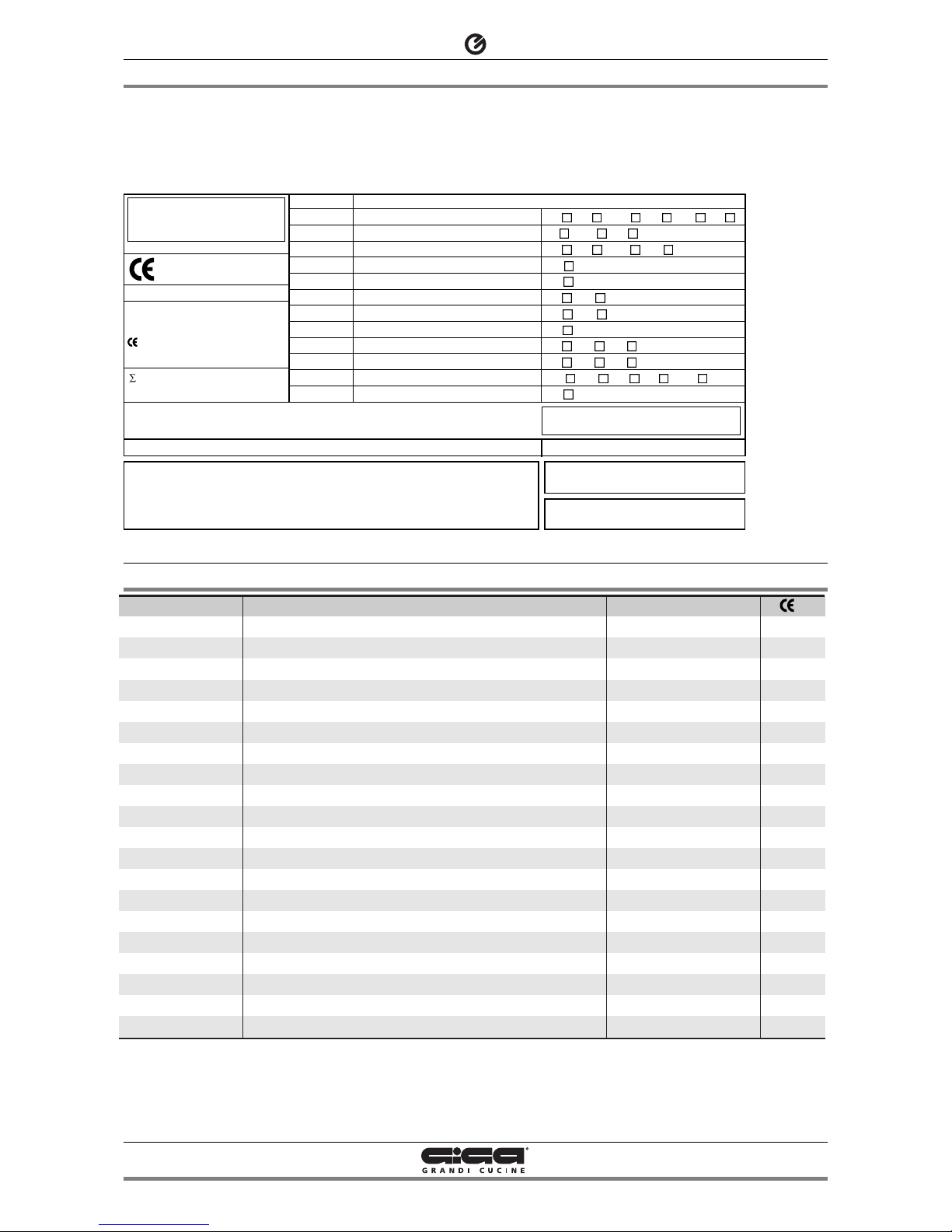
2 - CHARACTERISTICS OF THE APPLIANCES
The data plate is located on the front part of the appliance (on the
control panel).
Model
K2F
OP2F
K4F • K4FS
OP4F
K6F
OP6F
K8F
OP8F
K4FSFCG
K4FFG • K4FSFG
K4FSFCE
K4FFE • K4FSFE
K6FFG
K6FFGA
K6FFE
K8FFG
K8FFE
B4F
B6F
B8F
Version
2 burners - open compartment
2 burners, embossed
4 burners - open compartment
4 burners, embossed
6 burners - open compartment
6 burners, embossed
8 burners - open compartment
8 burners, embossed
4 burners - 1 gas oven GN 1/1 ventilated
4 burners - 1 gas oven GN 2/1
4 burners - 1 electric oven GN 1/1 ventilated
4 burners - 1 electric oven GN 2/1
6 burners - 1 gas oven GN 2/1 - cabinet
6 burners - 1 gas oven MAXI
6 burners - 1 electric oven GN 2/1 - cabinet
8 burners - 2 gas oven GN 2/1
8 burners - 2 electric oven GN 2/1
4 burners - double controls - open compartment
6 burners - double controls - open compartment
8 burners - double controls - open compartment
Dim.: LxWxH
400 x 900 x 900/970
400 x 900 x 270/340
800 x 900 x 900/970
800 x 900 x 270/340
1200 x 900 x 900/970
1200 x 900 x 270/340
1600 x 900 x 900/970
1600 x 900 x 270/340
800 x 900 x 900/970
800 x 900 x 900/970
800 x 900 x 900/970
800 x 900 x 900/970
1200 x 900 x 900/970
1200 x 900 x 900/970
1200 x 900 x 900/970
1600 x 900 x 900/970
1600 x 900 x 900/970
800 x 900 x 900
1200 x 900 x 900
1600 x 900 x 900
N.
51BQ2899
51BQ2899
51BQ2899
51BQ2899
51BQ2899
51BQ2899
51BQ2899
51BQ2899
51BQ2899
51BQ2899
51BQ2899
51BQ2899
51BQ2899
51BQ2899
51BQ2899
51BQ2899
51BQ2899
51BQ2899
51BQ2899
51BQ2899
0051
TIPO/TYPE
CAT/KAT GAS/GAZ G30 G31 G20 G25
II2H3B/P P mbar 30 30 20 II2H3+ P mbar 30 37 20 II2H3+ P mbar 28 37 20 II2L3B/P P mbar 30 30 - 25
II2ELL3B/P P mbar 50 50 20 20
II2E+3+ P mbar 28 37 20 II2H3B/P P mbar 50 50 20 I2E P mbar - - 20 II2H3B/P P mbar 30 30 - II2H3+ P mbar 28 37 20 I3B/P P mbar 30 30 - I3+ P mbar 28 37 - -
SE FI DK CZ SK SI
IT CH PT
ES IE GB GR
GB
DE
FR BE
AT CH
LU
EE LV LT
EE LV LT
NO MT CY IS HU
CY
MOD.
MOD.
ART.
N.
N.
Qn kW
m3/h
MADE IN ITALY
Predisposto a gas: - Gas preset: - Prevu pour gaz:
Eingestelt für Gas: - Preparado para gas: - Geschuckt voor:
V AC KW Hz
THE APPLIANCE MUST BE CONNECTED IN COMPLIANCE WITH CURRENT REGULATIONS AND
INSTALLED IN A WELL-VENTILATED ROOM. READ THE INSTRUCTION MANUAL BEFORE
INSTALLING AND USING THE APPLIANCE. THE APPLIANCE MUST BE INSTALLED BY QUALIFIED
PERSONNEL
G30/G31 30/37 mbar
G20 20 mbar
 Loading...