

GIG GMA200-MW4 Operation Manual
GfG GESELLSCHAFT FÜR GERÄTEBAU MBH▐ KLÖNNESTRASSE 99▐ 44143 DORTMUND, GERMANY▐ TEL. +49 / (0)231 / 564 00 –0 ▐ FAX +49 / (0)231 / 516 313
INFO@GFG-MBH.COM▐ WWW.GFG.BIZ▐ DORTMUND COUNTY COURT HR B 2742▐ CERTIFIED IN ACCORDANCE WITH DIN EN ISO 9001:2008▐ ATEX QM-CERTIFIED
Operation Manual
GMA200-MW4
Gas detection controller for wall mounting

2
Table of contents
Page
1. INTRODUCTION 3
1.1 For your safety 3
1.2 Application and purpose 3
1.3 Special conditions for safe application 3
2. GAS DETECTION CONTROLLER GMA200-MW4 4
2.1 General description 4
2.2 Device design 4
2.2.1 LED status displays 4
2.2.2 Graphical display 5
2.2.3 Visual and acoustic alarm 5
2.3 Internal relays of the GMA200-MW4 5
2.4 External relay with the relay module GMA200-RT 5
2.5 Relay configuration 5
3. ASSEMBLY AND INSTALLATION INSTRUCTIONS 6
3.1 Site of installation 6
3.2 Electrical connections 6
3.2.1 Safety information 6
3.2.2 Mains connection and separator 6
3.2.3 Floating relay contacts 6
3.2.4 External 24 V DC voltage supply 7
3.2.5 Connection of transmitters with an analogue interface 7
3.2.6 Connection of transmitters with a digital interface (RS485) 7
3.2.7 Connection of further devices with a digital interface (RS485) 7
3.2.8 Using the alarm acknowledgement inputs 7
3.2.9 Using the 4-20 mA current outputs 7
3.3 Commissioning 7
4. OPERATING INSTRUCTIONS 8
4.1 Measuring mode 8
4.2 Alarms 8
4.2.1 Alarm configuration 8
4.2.2 Alarm acknowledgement (Reset) 8
4.3 Relays 9
4.4 Faults 9
4.5 Data logger function (configured using the GMA200Config software) 9
4.6 Analogue outputs 10
5. KEYBOARD AND MENUS 10
5.1 Operation and menu navigation 10
5.2 Main menu 11
5.3 Service menu 11
6. ANNEX 11
6.1 Cleaning and care 11
6.2 Maintenance and service 11
6.2.1 Visual inspection 12
6.2.2 Functional testing 12
6.2.3 System check 12
6.2.4 Repair 12
6.3 Spare parts and accessories 12
6.4 Information on the environmentally sound disposal of used parts 12
6.5 Functional safety and parameters 13
6.6 Technical data 14
6.7 EC declaration of conformity 15

3
1. Introduction
1.1 For your safety
This user manual states the intended use of the product according to § 3 of the German Product
Safety Act (ProdSG) and helps to prevent hazards.
It must be read and observed by all persons who operate, service, maintain and inspect this
product. This product can serve its intended purpose only if it is operated, serviced, maintained
and inspected according to the instructions given by GfG Gesellschaft für Gerätebau mbH.
Otherwise, the warranty provided by GfG Gesellschaft für Gerätebau mbH becomes void. Settings
in service mode should only be carried out by experts.
1.2 Application and purpose
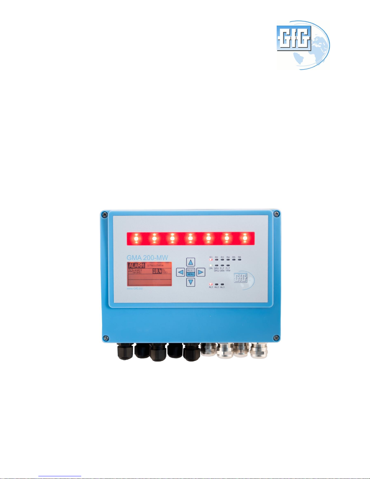
The GMA200-MW4 is a gas detection controller for wall mounting. Combined with connected
transmitters, it forms a fixed gas warning system for the continuous measurement of gas
concentrations and is used to issue a warning about combustible gases or vapours in the range
below the lower explosion limit and about toxic gases in the ambient air, as well as to measure
oxygen. External relay modules GMA200-RT are additionally available.
The GMA200Config software program is required to configure the controller GMA200-MW4 and the
relay module GMA200-RT.
The configuration software GMA200Config is not described in this user manual. (see UM 222-
000.30).
The relay module GMA200-RT/RTD is not described in this user manual. (see UM 222-000.24).
Operation and maintenance of the various transmitters are described in separate user manuals.
1.3 Special conditions for safe application
According to the requirements stipulated, e.g., by DIN EN 60079-29-1 section 4.2.3.2,
DIN EN 45544 and DIN EN 50104 at least one alarm threshold with self-locking must be
configured for potentially hazardous gas concentrations.
At least one internal relay must also be configured as the collective message for all measuring
point faults (FLT-TRM) and for GMA faults (FLT-GMA).
4
2. Gas detection controller GMA200-MW4
2.1 General description
The design of the gas warning controller GMA200-MW4 ensures flexible, simple and clearly
structured operation in industrial and commercial applications for measuring combustible and
toxic gases/vapours, and for measuring oxygen concentrations.
Using the GMA200Config software program, it is possible to quickly and easily configure measuring
points and relays even when extending already installed GMA200-MW gas warning systems.
Measuring point designation, transmitter type, gas type and measuring range, as well as three
individual or specified alarm thresholds, can, e.g., be configured for each measuring point.
2.2 Device design
Up to 4 transmitters with 4-20 mA or 0.2-1 mA output can be connected to the analogue inputs of
the gas detection controller GMA200-MW4. A microprocessor evaluates the analogue input signals of
the connected transmitters, and a clearly structured display and LEDs indicate the status of the gas
detection controller, each measuring point and the relays.
2.2.1 LED status displays
During operation, LED status displays at the gas detection controller GMA200 indicate the following
statuses according to the event:
-
Operating status (ON)
→
green
-
Alarm 1 (AL1)
→
red
-
Alarm 2 (AL2)
→
red
-
Alarm 3 (AL3)
→
red
-
Service (SRV/SRQ) required
→
yellow
-
Fault (FLT) GMA
→
yellow
-
Fault (FLT) TRM
→
yellow
- Relay 1 (R1) – Relay 6 (R6)
→
red
(Relay activated in the case of an alarm or fault)
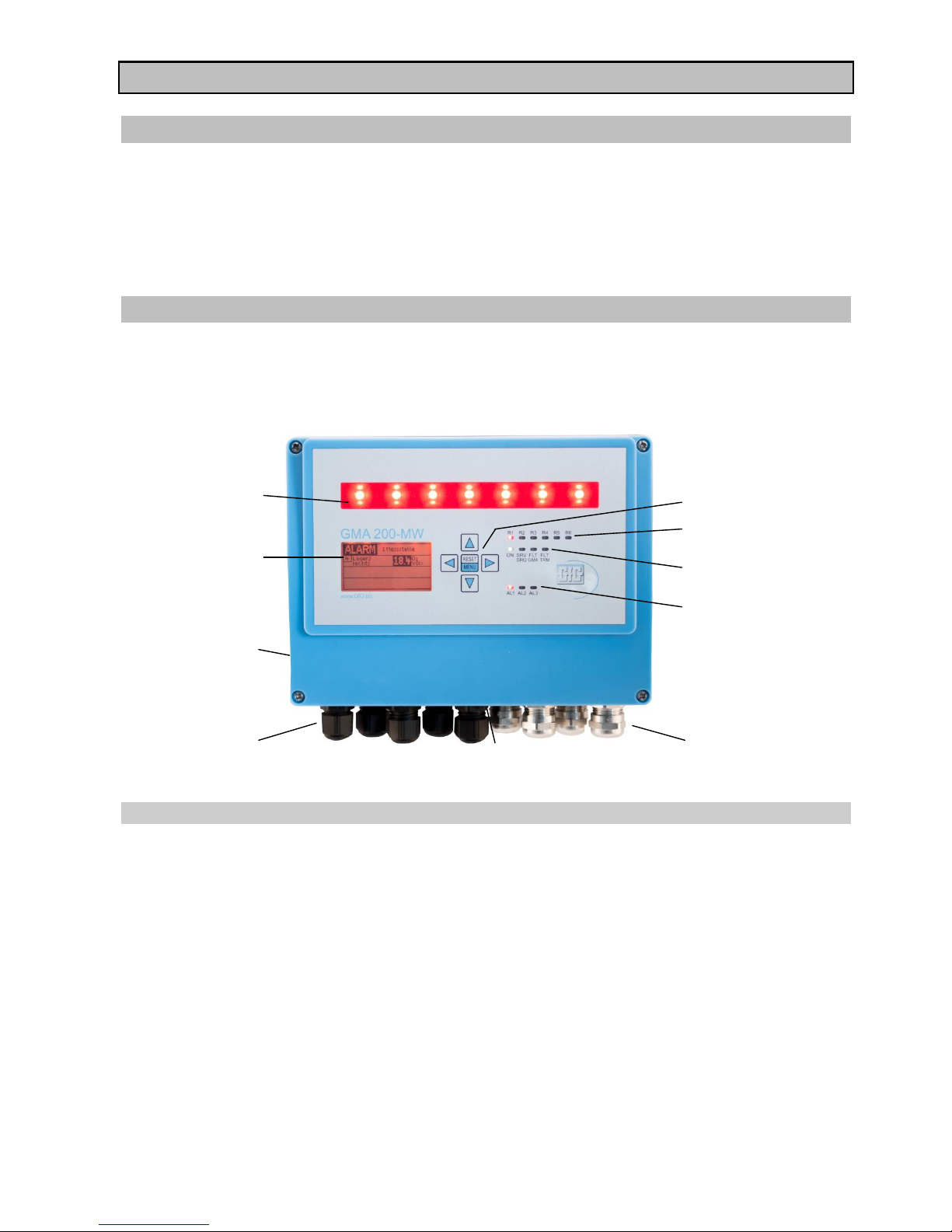
Control buttons
Status display of the
internal relays
Status display of
operating statuses
Status display for
alarms
Cable glands for
transmitter
connection cables
Alarm light
LCD display
Type plate with
date of production
Cable glands for
mains and relay
connection cables
Alarm horn
5
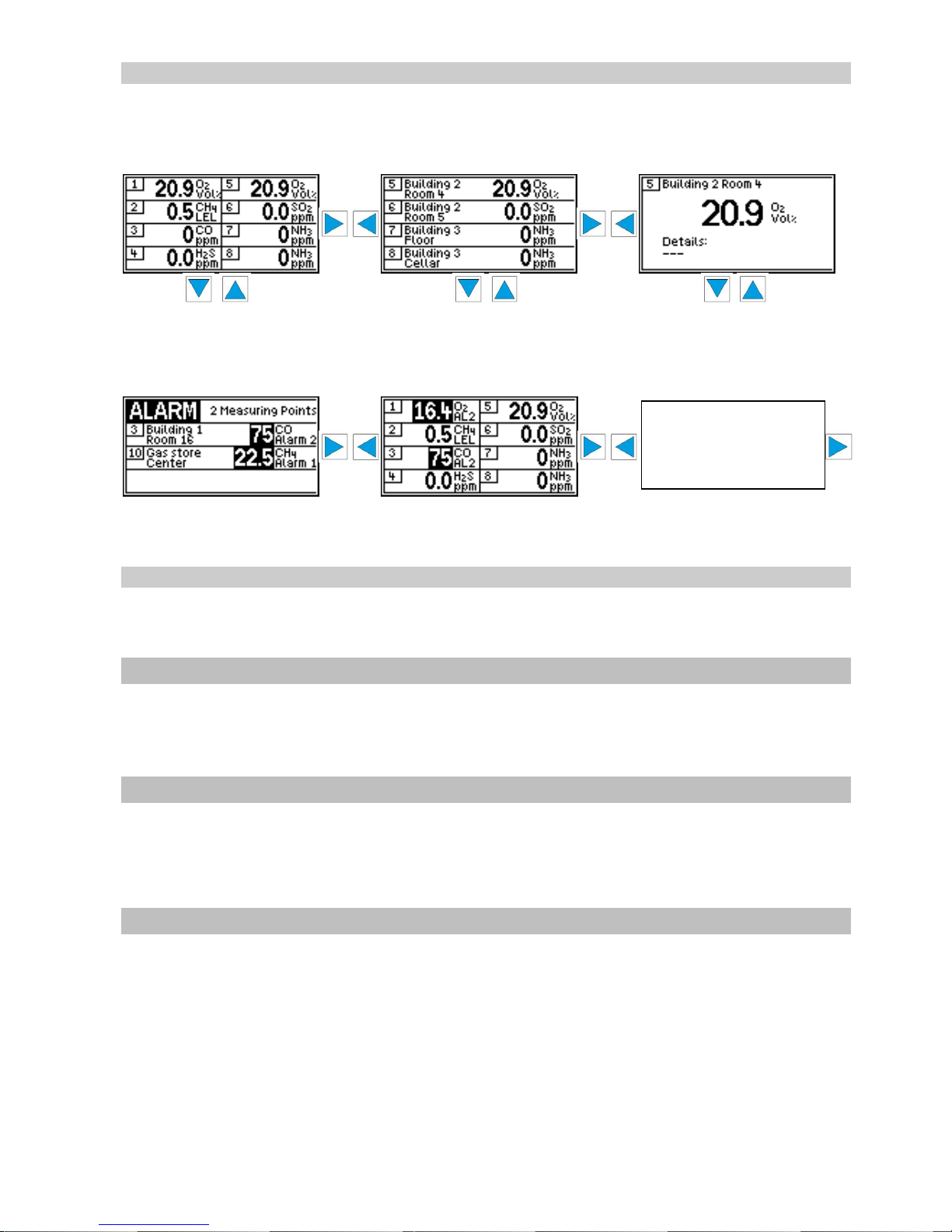
2.2.2 Graphical display
Currently measured values are shown on the display for each measuring point. The display for the
measuring points can be optionally set via the menu navigation (also see section 5.1), e.g.:
Display in normal mode
Display of 8 measuring points Display of 4 measuring points Display as single measuring point
for displaying for displaying for displaying
measuring point 9–16 measuring point 5-8 \ 13-16 measuring point 6 \ 4
Display for alarms
First display for alarms Alarm for 2 measuring points
The graphical display is backlit; the light intensity can be increased via any control button. In the
event of a gas alarm or faults, the display lighting is automatically activated with a red
background.
2.2.3 Visual and acoustic alarm
An alarm light and a horn for central visual and acoustic alarm are integrated in the wall
mounting housing GMA200-MW4 and triggered when the assigned alarm configuration for one or
several measuring points is exceeded or not achieved (for alarm configuration, see section 4.3).
2.3 Internal relays of the GMA200-MW4
The gas detection controller GMA200-MW4 features a total of 6 relays. In order to realise specified
safety measures and alarms, 4 relays can be freely configured using the GMA200Config software
program. An additional relay is available for each controller as a safety-related fault message and
maintenance relay.
2.4 External relay with the relay module GMA200-RT
The relay module GMA200-RT enables the addition of a further 16 freely configurable relays. A total
of 4 relay modules with 64 additional relays can be managed via the controller GMA200-MT. The
relay modules RT are connected to the controller GMA200 via the digital interface RS485 which also
enables the spatial separation of the relay modules (max. 1,000 m).
The relay module is not described in this user manual (see UM 222-000.24).
2.5 Relay configuration
Configuration of the relays using the GMA200Config software offers extensive options, e.g. the
allocation of individual or several measuring points to relays.
Configuration options:
- Single alarm per measuring point and alarm threshold
- Configuration of And/Or conjunctions
- Collective or group alarms
- Fault messages
- Voting functions
- Open-circuit principle / Closed-circuit principle
each for the gradual display
with 4 measuring points up
to the display of the single
measuring point
 Loading...