

GIG GMA 200-MT series, GMA 200-MT6, GMA 200-MT16 Operation Manual
Worldwide Manufacturer of Gas Detection Solutions
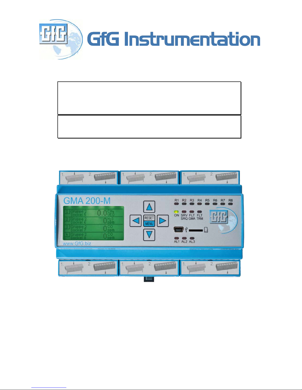
GMA 200-MT
Operations Manual
1194 Oak Valley Dr, Ste 20, Ann Arbor MI 48108 USA
(800) 959-0329 • (734) 769-0573 • www.goodforgas.com


Table of Contents Page
INTRODUCTION 2
For your safety 2
Application 2
Special conditions for safe operation 2
GAS DETECTION CONTROLLER GMA 200-MT 3
General description 3
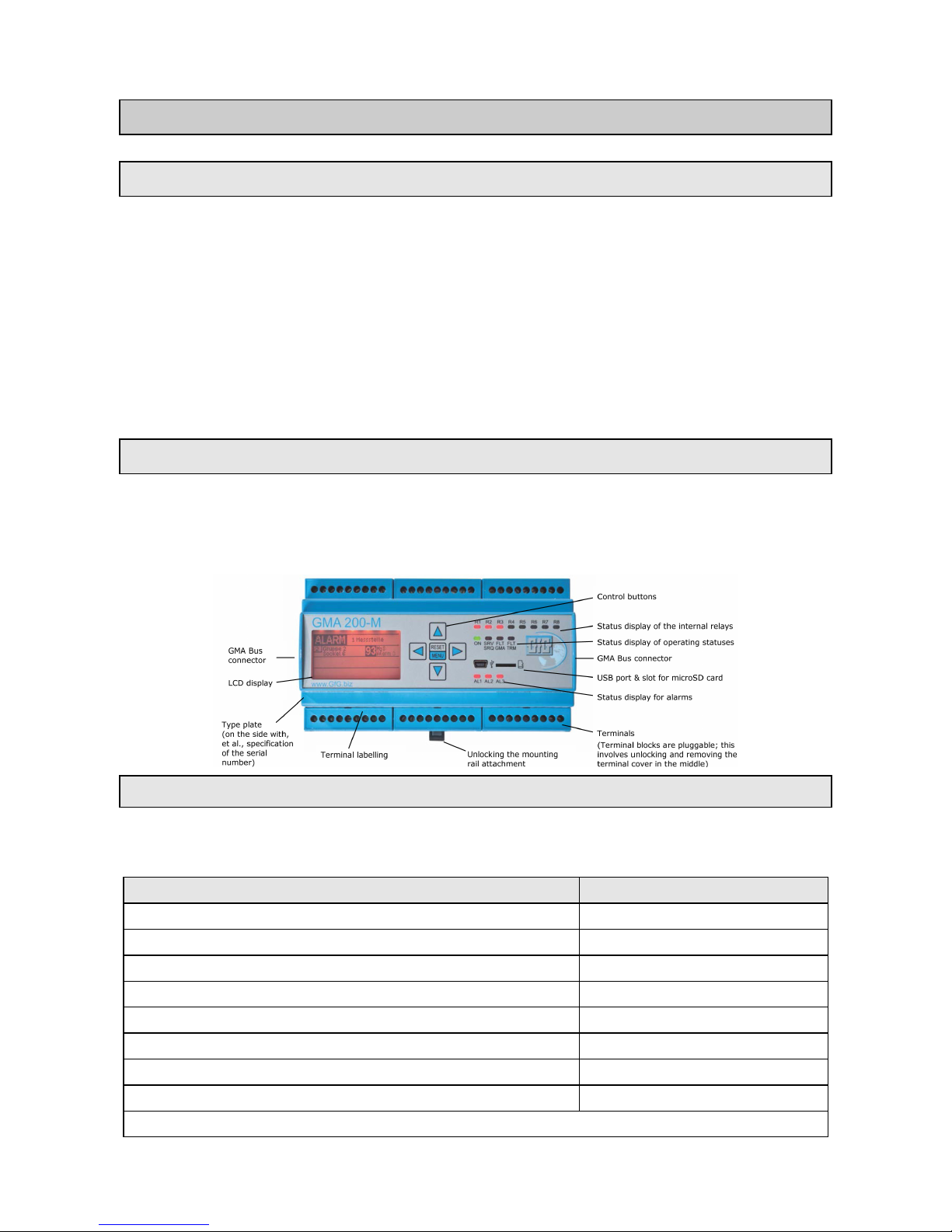
Device design 3
LED status displays 3
Graphical display 4
Internal relays of the GMA 200-MT 4
External relay with the relay module GMA 200-RT 4
Relay configuration 5
ASSEMBLY AND INSTALLATION INSTRUCTIONS 5
Site of installation 5
Electrical connections 5
Safety information 6
Floating relay contacts 6
24 V DC voltage supply 6
Connection of transmitters with an analog interface 6
Connection of transmitters with a digital interface (RS485) 7
Connection of further devices with a digital interface (RS485) 7
Using the alarm acknowledgement inputs 7
Using the 4-20 mA current outputs 7
Commissioning 8
OPERATING INSTRUCTIONS 8
Measuring mode 8
Alarms 8
Alarm configuration 9
Alarm acknowledgement (Reset) 9
Relays 9
Faults 10
Data logger function (configured using the “GMA200Config” software) 10
Analog outputs 11
KEYBOARD AND MENUS 12
Operation and menu navigation 12
Main menu 12
Service menu 13
APPENDIX 14
Cleaning and care 14
Maintenance and service 14
Visual inspection 14
Functional testing 14
System check 14
Repair 15
Parts and accessories 15
Technical data 16
EC declaration of conformity 17

Introduction
For your safety
As with any piece of complex equipment, the GMA 200-MT will do the job it is designed to do
only if it is used and serviced in accordance with the manufacturer's instructions. Please protect
yourself and your employees by following the instructions in this manual. All individuals who have
or will have the responsibility for using and servicing this product must carefully read this manual.
The warranties made by GfG with respect to the product are void if functions or parameters are
changed without the permission of GfG. They are also void if the product is not used and serviced
in accordance with the instructions in this manual. Failures or false alarms caused by interfering
gases or electrical signals are not part of the warranty obligation. The above does not alter any
statements by GfG regarding warranties, conditions of sale and/or delivery.
Application
The GMA 200-MT6 and GMA 200-MT16 are gas detection controllers for mounting rail assembly.
Combined with connected transmitters, they form a fixed gas warning system for the continuous
measurement of gas concentrations and are used to issue a warning about combustible gases or
vapors in the range below the lower explosion limit and about toxic gases in the ambient air, as well
as to measure oxygen.
External relay modules GMA 200-RT are additionally available.
The “GMA200Config” software program is required to configure the controllers GMA 200-MT6
and GMA 200-MT16 and the relay module GMA 200-RT.
Special conditions for safe operation
According to the requirements stipulated, (e.g., by DIN EN 60079-29-1, DIN EN 45544 and DIN
EN 50104) at least one alarm threshold with self-locking must be configured for potentially
hazardous gas concentrations.
Gas detection controller GMA 200-MT
General Description
The fundamental configuration and design of the GMA 200-MT6 and GMA 200-MT16 gas
detection controllers ensure flexible, simple and clearly structured operation in industrial and
commercial applications for measuring combustible and toxic gases/vapors and oxygen
concentrations.
Using the "GMA200Config" software program, it is possible to quickly and easily configure
measuring points and relays even when extending already installed GMA200 gas warning systems.
Among other things, measuring point designation, transmitter type, gas type and measuring range,
as well as three individual or specified alarm thresholds, can be configured for each measuring
point.
Device design
Up to 6 transmitters can be connected to the analog inputs of the GMA 200-MT6 and up to 16
transmitters with 4-20 mA or 0.2-1 mA output to the GMA 200-MT16. A microprocessor evaluates
the analog input signals of the connected transmitters, and a clearly structured display with LEDs
indicate the status of the gas detection controller, each measuring point and the relays.
LED status displays
During operation, the LED status displays at the GMA 200 controller indicating the following
statuses according to the event:
Event LED status display
Operating status (ON) green
Alarm 1 (AL1) red
Alarm 2 (AL2) red
Alarm 3 (AL3) red
Service (SRV/SRQ) required yellow
Fault (FLT) GMA yellow
Fault (FLT) TRM yellow
Relay 1 (R1) – Relay 8 (R8) red
(Relay activated in case of an alarm or fault)
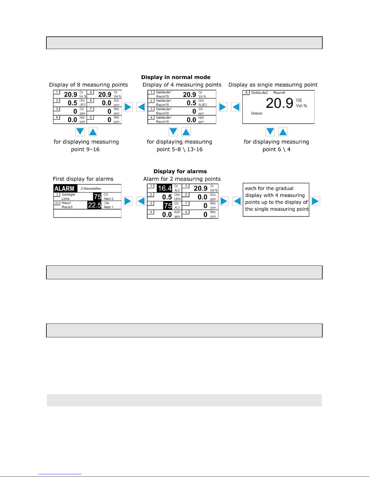
Graphical display
The display shows the currently measured values for each measuring point. The display for the
measuring points can be optionally set through the menu shown below.
The display is backlit; the light intensity can be increased using any control button.
In the event of a gas alarm or faults, the display lighting is automatically activated with a red
background.
Internal relays of the GMA 200- MT
The GMA 200-MT6/ GMA 200-MT16 controllers feature a total of 8 relays. In order to realize
specified safety measures and alarms, 6 relays can be configured using the “GMA200Config”
software program. An additional relay is available for each controller as a safety-related fault
message and maintenance relay.
External relay with the GMA 200-MT relay module
The GMA 200-RT relay module enables the addition of 16 more freely configurable relays. A total
of 4 relay modules with 64 additional relays can be managed via the GMA 200-MT controller. The
GMA 200-RT relay modules are connected to the GMA 200 controller using the RS-485 digital
interface, which also enables the spatial separation of the relay modules (max. 1,000 m).
The relay module is not described in this user manual.
 Loading...