

GIG G460 Operation Manual

GfG GESELLSCHAFT FÜR GERÄTEBAU MBH▐ KLÖNNESTRASSE 99▐ D-44143 DORTMUND▐ TELEPHONE +49 / (0) 2 31 / 5 64 00 –0 ▐ FAX +49 / (0) 2 31 / 51 63 13
INFO@GFG-MBH.COM ▐ WWW.GASDETECTION.BIZ▐ AMTSGERICHT DORTMUND HR B 2742▐ CERTIFIED AS PER DIN EN ISO 9001:2000▐ ATEX QM CERTIFICATE
Operation Manual
Microtector II G460
1 to 7-Gas Detector

2
GfG Products For Increased Safety
Congratulations!
You decided for a high technology product of GfG. A good choice!
Our detectors are characterized by reliability, safety, best
performance and economic efficiency.
They comply with national and international directives.
This manual will help you to operate the detector quickly and safely.
Please take note of the operational hints before putting into
operation!
For any questions please feel free to contact us.
GfG Gesellschaft für Gerätebau mbH
Klönnestraße 99
D-44143 Dortmund
: +49 - 231 – 564 000
Fax: +49 – 231 - 516 313
www.gfg.biz
info@gfg.biz

3
Content
Page
INTRODUCTION 5
For your safety 5
Application and purpose 5
Special conditions for safe use 6
Design 6
OPERATIONAL HINTS 7
Switching On and Off 7
Additional Messages during Detector Start 7
Detection Mode 8
Battery Capacity and Battery Alarm 8
Alarms 8
Reset of Alarms 9
STEL, TWA, Peak, Minimum Values 9
Flip-Flop Display, Zoom Display 9
Peak – Display of Peak Values 10
Turn On /Off Lights 10
Display Illumination 10
Storing Measurement Data with the Data Logger 10
Influence of Oxygen and Interfering Gases 11
Special Notes for LEL Monitoring 11
HI%-Measurement of Methane resp. Natural Gas
[#]
11
Service Mode 11
Main Menu 11
Location – Entering a Location 12
User – Entering User Name 12
Data Logger Settings 12
Signal – Selection of Confidence Bleep 13
AutoCal – AutoCal-Adjustments 13
Options – Anti-Lazy-Battery, Alarm Volume, Display Contrast 14
Tolerance band on/off 14
Service Menu 14
Sensor Menu – Sensor-specific Functions 14
Zeroing – Adjustment of Zeropoint 15
Calibration – Sensitivity Adjustment 16
Alarms – Adjusting the Alarm Thresholds 16
Calibration Data - Date & Status of last calibration 17
Information – Sensor Information 17
Unit and Gas - Selection of Detection Range 17
System Menu – General Settings 18
Bump Test – Date and Interval 18
Calibration (ZERO+CAL) – Date and Interval 18
Inspection – Date of next Inspection 19
Time – Date and Time of the Instrument 19
System Options – Language, Vibration and Latching Alarm, SD Card Check, Auto Save 19
Sensor Selection – Activation / Deactivation 20
AutoCal-Air – Sensor Release for AutoCal Adjustments 20
AutoCal-Gas – Sensor Release for AutoCal Adjustments 20
Information – Detector, Firmware Version, Serial Number, Supply Module 20

4
Charging of Rechargeable Battery Pack 20
Lazy-Battery-Effect on NiMH Battery Packs and its Clearance 21
Replacement of Alkaline or Rechargeable Batteries 22
ANNEX 22
Cleaning 22
Maintenance and Inspection 22
Service - Repair 22
Calibration Accessories 23
Test with Docking Station DS400 23
Trouble Shooting 23
Accessories and Spare Parts 25
Hints for a non-polluting disposal of old parts 26
Sensor Types and Detection Ranges 26
Sensor Specification 27
Alarm Thresholds – Standard Setpoints 32
Technical Data 33
EC-Type Examination Certificate 35

5
Introduction
For your safety
According to § 3 of the law about technical working media and consumer products for Germany according to
“Geräte- und Produktsicherheitsgesetz (GPSG) this manual points out the proper use of the product and
serves to prevent dangers. It must be read and adhered to by all persons who use, service, maintain and
check this product. This detector can do the job designed to do only, if it is used, serviced, maintained and
checked according to the instructions given by GfG Gesellschaft fuer Geraetebau. The warranties made by
GfG with respect to the product are voided, if the product is not used, serviced, maintained and checked in
accordance with GfG’s instructions. The above does not alter statements regarding warranties and liabilities
in GfG’s general conditions of sale and delivery. Repairs must only be done by skilled personnel resp. by
trained persons. Modifications and changes of the product require GfG’s permission. Unauthorized
modification of the product results in the exclusion of any liability for possible damage. Make sure that only
genuine GfG accessories are used with the product. Repairs require the use of spare parts released by GfG.
Application and purpose
The G460 is a handheld detector for personal protection from hazards occurring by toxic or explosive gases
and vapors and also by a lack of oxygen or oxygen surplus. The detector measures permanently in diffusion
mode and gives a visual and audible alarm, if a gas-induced danger builds up. The G460 is approved for the
use in explosion endangered areas and is subject to an EC-Type Examination Certificate issued by DEKRA
EXAM GmbH, according to directive 2014/34/EU:
Certificate: BVS 06 ATEX E 017 X
Labelling:
II 2G
Ex ia de IIC T4 Gb -20°C≤Ta≤+50°C (NiMH-II)
Ex ia de IIC T3 Gb -20°C≤Ta≤+50°C (NiMH)
Ex ia de IIC T4/T3 Gb -20°C≤Ta≤+45°/+50°C (Alkaline)
Labelling:
I M1
Ex ia I M -20°C≤Ta≤+50°C (NiMH-II, NiMH)
The temperature class of the detector in group II depends on the supply module used. When using the
„NiMH-II“ accumulator, temperature class T4 is valid for ambient temperatures of –20°C to +50°C, while
temperature class T3 is valid when using the „NiMH“ accumulator. Both supply modules are identified by a
black enclosure with an inside label showing the type and temperature class. When using the Alkaline
batteries (grey housing), temperature class T4 is valid for ambient temperatures from -20°C to +45°C resp.
temperature class T3 for ambient temperatures of -20°C to +50°C.
For the use in group I it is only allowed to use the „NiMH” or „NiMH-II” accumulator. The detector is valid for
ambient temperatures of -20°C to +50°C.
For the use in explosion endangered areas with a measurement function for the explosion protection there is
a supplement for the G460 to the above mentioned EC-Type Examination Certificate of DEKRA EXAM GmbH
according to guideline 2014/34/EU. Basis of the test were the standards DIN EN 60079-29-1 „Gas detection
instruments – requirements to the operational behavior of instruments for the measurement of combustible
gases” and DIN EN 50271 “Electronic instruments for the detection and measurement of combustible gases,
toxic gases or oxygen – requirements and testing for warning instruments, that use software and/or digital
technology”. Furthermore the G460 was examined on its measurement ability by DEKRA EXAM GmbH on the
basis of the standards DIN EN 50104 “Electronic instruments for the detection and measurement of oxygen
– requirements to the operational behavior and testing method” and DIN EN 45544-1/-2 “Electronic
instruments for the direct detection and direct measurement of the concentration of toxic gases and vapours
part 1: common requirements and testing methods” and part 2: requirements to the operational behavior of
instruments for the measurement of concentration in threshold ranges”. This is approved by the relevant
Type Examination Certificate with the number PFG 09 G 001.
6
The tests of the measuring function contain
f
ollowing sensors and detection ranges:
EC-Type Examination Certificate
BVS 06 ATEX E 017 X
(4. and 7. supplement)
MK211-8 for 0..5 Vol.% CH
4
(CC)
MK211-6, MK211-7 for 0..100%LEL CH4, C3H8, C6H
14
(CC)
MK227-5, MK231-5 for 0..100%LEL C
3H8
, C9H
20
[#]
(IR)
Type Examination Certificate
PFG 09 G 001
MK224-5, MK231-5 for 0.02..5%Vol CO2 (IR)
MK344-4, MK369-6 for 2..500ppm, 5..500ppm CO (EC)
MK427-5 for 0..25%Vol O
2
(EC)
MK429-5 for 0.2..100ppm H2S (EC)
At
[%]
: The measuring function for n-nonane was tested in the range of 0..60%LEL.
The functions being marked with [#] were not subject of the test of the measurement function.
Special conditions for safe use
In explosion endangered areas the G460 must be used properly. This means that the detector must be
carried at your body and must not be laid down unattended, to prevent an electrostatic charge of the clip.
For the use in mine (group I) it is only allowed to use the „NiMH” or „NiMH-II” accumulator. In case readings
in gas-free environments show a permanent zero-point deviation, a zero-point adjustment is necessary.
Especially after a heavy impact stress the zero-points of the sensors have to be checked and optionally readjusted. In case the CC sensor shows “over-range” after a stress impact, the alarm has to be reset in fresh
air and the zero-point has also to be re-adjusted. If the G460 is operated continuously for more than one
day, the instrument should be turned off and on again every 24 hours latest. Within the system option menu
the deactivation of the latching alarm is not allowed for the use as a function tested measurement
instrument. For functional and Ex-protection reasons only GfG approved micro SD-memory cards must be
used (s. chapter “Accessories and Spare Parts”).
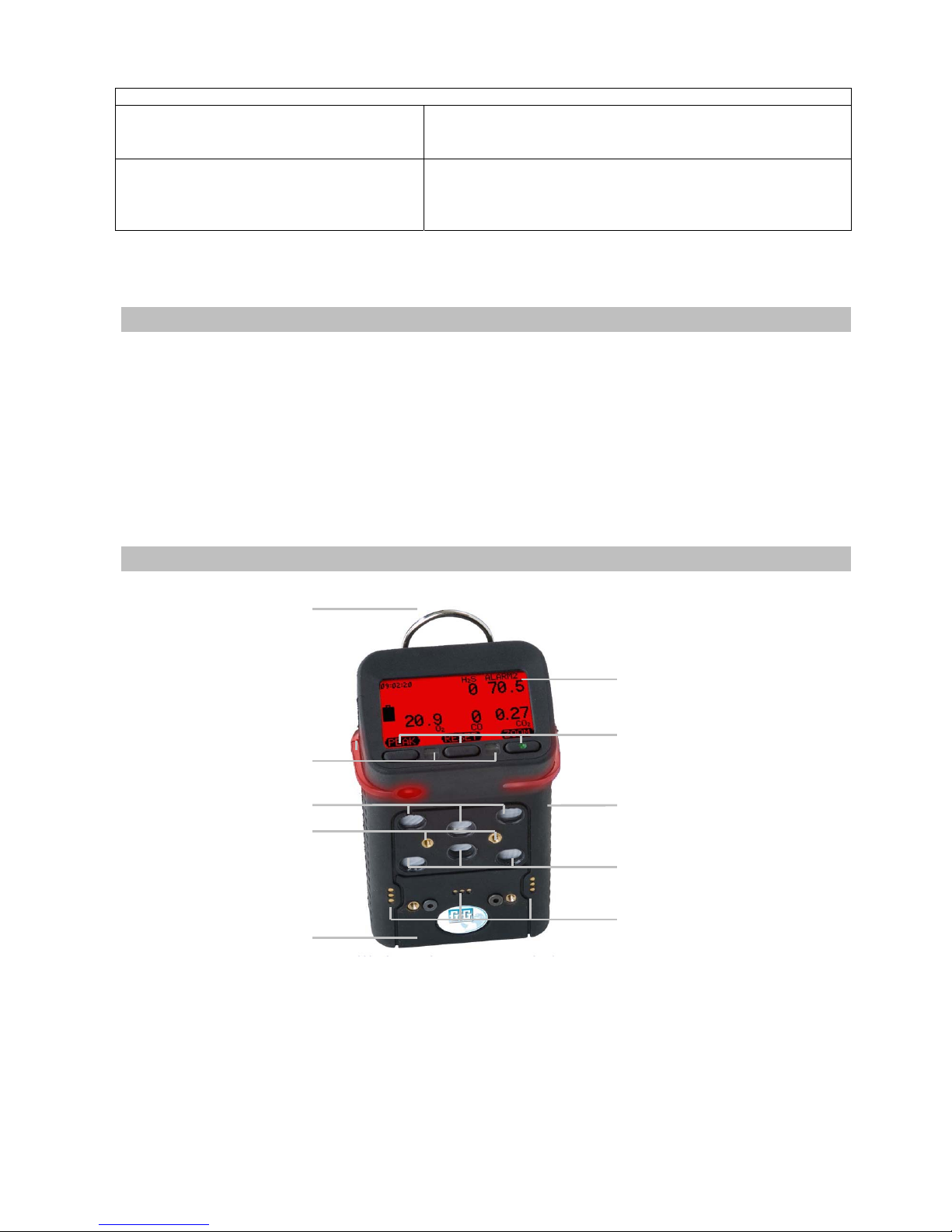
Design
Carrying stra
p
Display
Battery pack
(reverse)
Keys
Alarm LEDs
Screw connectors for
pump or calibration
cap or charger cap
Contacts
for
p
eriphery
Diffusion inlet
(
EC
IR CC
)
Type label (backside)
with production date e.g.
SN: 0911xxxx (09=year, 11=month)
Diffusion inlet
(
EC1 IR EC2/PID
)
7
Operational Hints
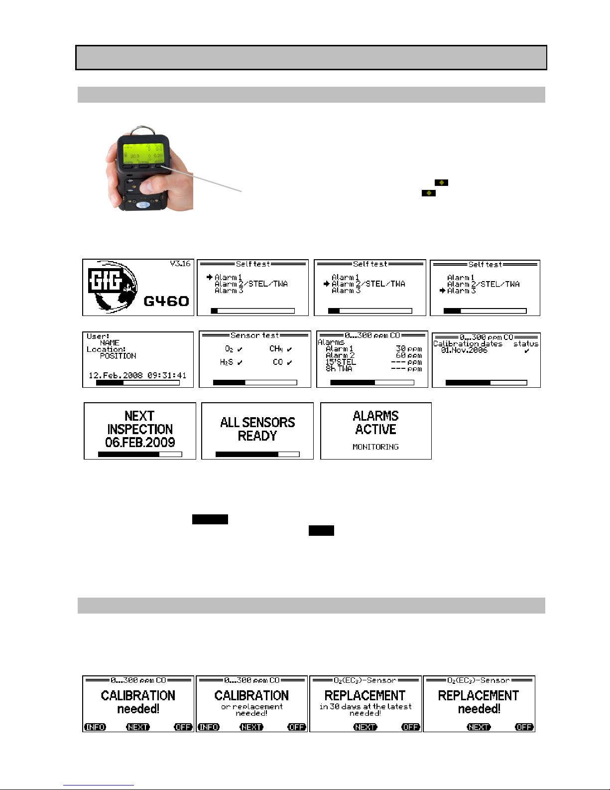
Switching On and Off
Press the right key shortly to switch the G460 on .
To switch the G460 off, press the right key for approx. 5 seconds.
Release the key when the display reads SWITCH-OFF 0.
During charging the standard detection mode is automatically switched off
and the charging time is displayed.
After switching on the G460 starts a self-test and displays information about the firmware version, the
built-in sensors with detection ranges and alarm thresholds and the date of the next inspection. During the
self test the visual and audible alarms are triggered like gas alarms.
Alarm thresholds and calibration data are displayed for all sensors connected. Only as an example it is only
CO which is being described here. Depending on the status of the sensors, the instrument may provide
additional messages, which may have to be confirmed. Please refer to “Additional messages during
detector start” for further information.
If you push the left key (DETECT), or if you do not hit any key, during the warm-up period, the detector
goes to detection mode. By pressing the right key (ZERO) the automatic fresh air adjustment is started.
When the detector is equipped with an oxygen sensor, its sensitivity is set to the normal 20.9Vol% oxygen
which are present in fresh air.
Once the self test is completed, the instrument is ready to use after about one minute. By hitting the
middle key readings and messages can be reset.
Additional Messages during Detector Start
When started, the G460 tests the sensors and supervises their adjustment data. For sensors, which were
not adjusted yet or whose adjustment is older than one year, the message “Calibration needed!” is
displayed. The reduced adjustment interval of used-up sensors might result in the message “Calibration or
replacement is needed!”. Exhausted sensors are indicated by the message “Replacement needed!”, when
the detector is started. These messages must be acknowledged by key.
8
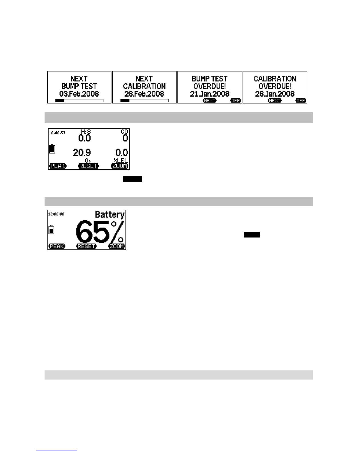
When a docking station is used for instrument check, the G460 may include intervals for bump test and
calibration of sensors. The dates for the next bump test or for the next calibration are calculated
automatically on the basis of the last check. Depending on what becomes necessary next, the date for the
next bump test or for the next calibration will be indicated, when the detector is started. Should the
relevant date be exceeded, the G460 indicates this as „overdue“. This message must be acknowledged by
key.
Detection Mode
The G460 is ready for operation, if all measurement values, the unit,
the gas, the battery capacity and the time are displayed. With more
than five measurement values being displayed, the clock will not be
shown due to space restrictions. The detector check whether the preset
thresholds for the individual gases are exceeded or deviated (O
2
).
When more than two measurement values are displayed simultaneously, either the gas type or the unit is
shown. By hitting the right key (ZOOM) measurement values can be displayed individually with gas type and
unit.
Battery Capacity and Battery Alarm
When in detection mode, the battery capacity can be determined from
the battery symbol that is shown on the left of the display. The black
bar represents the residual capacity. The residual capacity can also be
displayed as a number by pressing the right (ZOOM) button. (*1)
The fully charged battery pack or fresh batteries of the G460 have a capacity (depending on sensor
combinations) of approx. 5-170 hours of continuous operation (see technical data). The operational time
may be reduced by activated alarms. In the top left corner of the display the remaining battery capacity is
indicated by a battery symbol. The black area represents the remaining capacity. If the charging status
reaches a low level which is shown as a blank battery symbol, the instrument switches to “energy-saving
mode”. In this mode the green background illumination will not be activated whenever you hit any key. In
case of gas alarms also the red display illumination will not be triggered. The alarm will only be shown by
the alarm LEDs and with a maximum volume of 90 db(A). If the charging status sinks even further, battery
alarm is given acoustically. In this status the battery symbol flashes. The maximum remaining term is
displayed every minute. After 15 minutes the instruments automatically shuts off with a clear acoustic
signal. The display reads “OFF” for 5 minutes. Selecting the “Anti-Lazy-Battery” within the option menu the
instrument does not automatically shut off after 15 minutes but when falling below a minimum voltage.
To (*1): When using the NiMH F25 or NiMH-II A21 power pack, there can especially be an elevated residual
capacity shown if relatively new batteries are being used. In extreme cases, a full battery can be indicated
during half of the life. The residual capacity display then falls considerably faster. This normalises itself the
older the batter becomes or in relation to the number of charging/discharging cycles. The battery alarm is
triggered in good time however, irrespective of this.
Alarms
Should the measured gas concentration exceed a pre-set threshold, the detector immediately gives an
audible and visual alarm. The display indicates which gas has caused the alarm. An extremely loud acoustic
alarm (103 dB(A) at 30 cm) and bright flashing alarm LEDs provide reliable warning for dangerous gas
concentrations. In case of a gas alarm the colour of the whole display turns into orange or red depending on
the alarm status. The G460 provides up to three alarm modes. The LO-alarm AL1 can be reset, while the HIalarms AL2 and AL3 are latching (default). There are three alarm levels for oxygen and combustible gases
9
(e.g. CH4), and two thresholds for toxic gases (CO, H2S). For toxic gases the G460 provides additional
alarms for exceeding of short term exposure level (STEL) and time weighted average (TWA). For further
information see “Alarm Thresholds – Standard Setpoints” and “Alarms – Adjusting the Alarm Thresholds”.
The alarm can also be triggered in combination with a vibration alarm, if the instrument provides a relevant
“battery pack with integrated vibrator”.
Kind of alarm Sensors
Number
of Alarms
Description
Instantaneous
value (AL)
oxygen
combust. gases
toxic gases
3
3
2
An instantaneous alarm is activated immediately, if the
gas concentration exceeds resp. falls below a pre-set
threshold. The alarm thresholds are adjustable.
Short term
exposure level
(STEL)
toxic gases 1
The short term exposure level (STEL) is the average
concentration over a period of 15 minutes. The STEL alarm
is not latching. It resets automatically as soon as the
concentration has fallen below the threshold.
Time weighted
average
(TWA)
toxic gases 1
The time weighted average (TWA) refers to an 8 hours
shift and calculates the average concentration. The TWA
alarm cannot be reset. It is only de-activated, if the
detector is switched off.
The alarms are prioritized as follows: Power fault, overrange, AL3, TWA > AL2, STEL > AL1, underrange >
temperature fault.
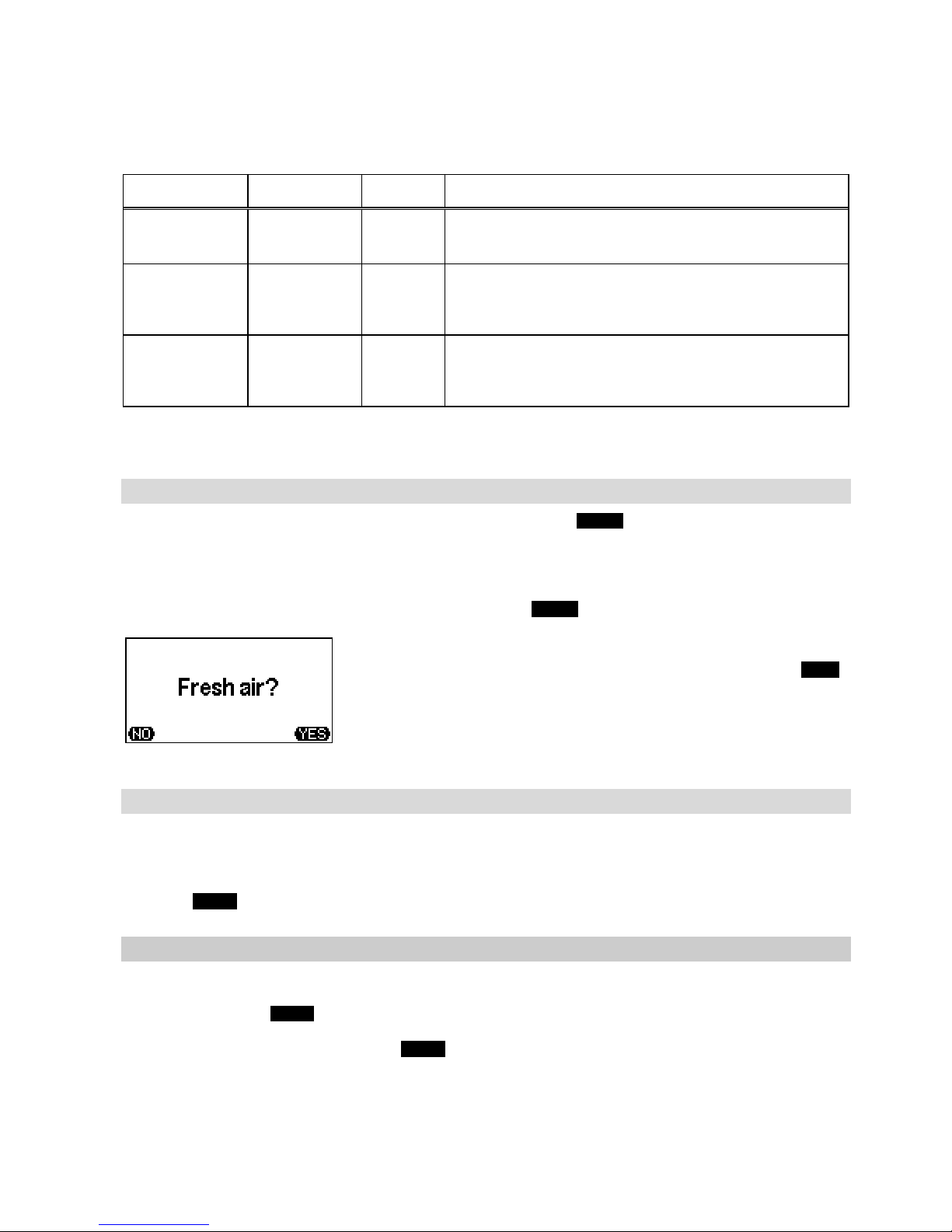
Reset of Alarms
The latching (default) alarms 2 and 3 can be reset by pressing the RESET key, if the gas concentration has
fallen below or exceeded (O2) the pre-set thresholds. Alarm 1 is not latching and resets automatically, when
the alarm condition does not exist any longer. If the detection range of the CC sensor (e.g. CH4) is
exceeded, the display additionally reads „OVER RANGE“ instead of the value, for gas concentrations above
110 % LEL. In this case the sensor is deactivated to avoid damage. The alarms and the message “OVER
RANGE” remain. This alarm can only be reset by pushing the RESET key. Then the display asks:
Only if you made sure that the sensor is not exposed to combustible
gas but to fresh air only, you may answer this question with YES .
In this case the sensor turns on again and indicates gas concentrations
after a short warm-up time!
For further details please refer to „Special Notes for LEL Monitoring“.
STEL, TWA, Peak, Minimum Values
After switching the detector on, measurement is effected continuously in diffusion mode. In this mode, all
concentrations are shown in the display. In addition, short term and long-term averages (STEL and TWA)
are calculated for toxic gases, and for non-toxic gases peak and minimum values (MAX and MIN) are stored.
The stored values can be read from the display, if you turn to the relevant display mode by means of the
right key (ZOOM, see below).
Flip-Flop Display, Zoom Display
The display can be turned by 180° by pressing the right and the left key simultaneously and then releasing
them. This allows easy reading when carrying the detector on the belt. For activating the zoom display,
press the right key (ZOOM). Press the key shortly to display one value. Repeated pressing of this key
displays the individual measurement values of the individual sensors in zoomed reading one after the other:
When a zoomed value is displayed, press ZOOM long to change to the following detail reading:
10
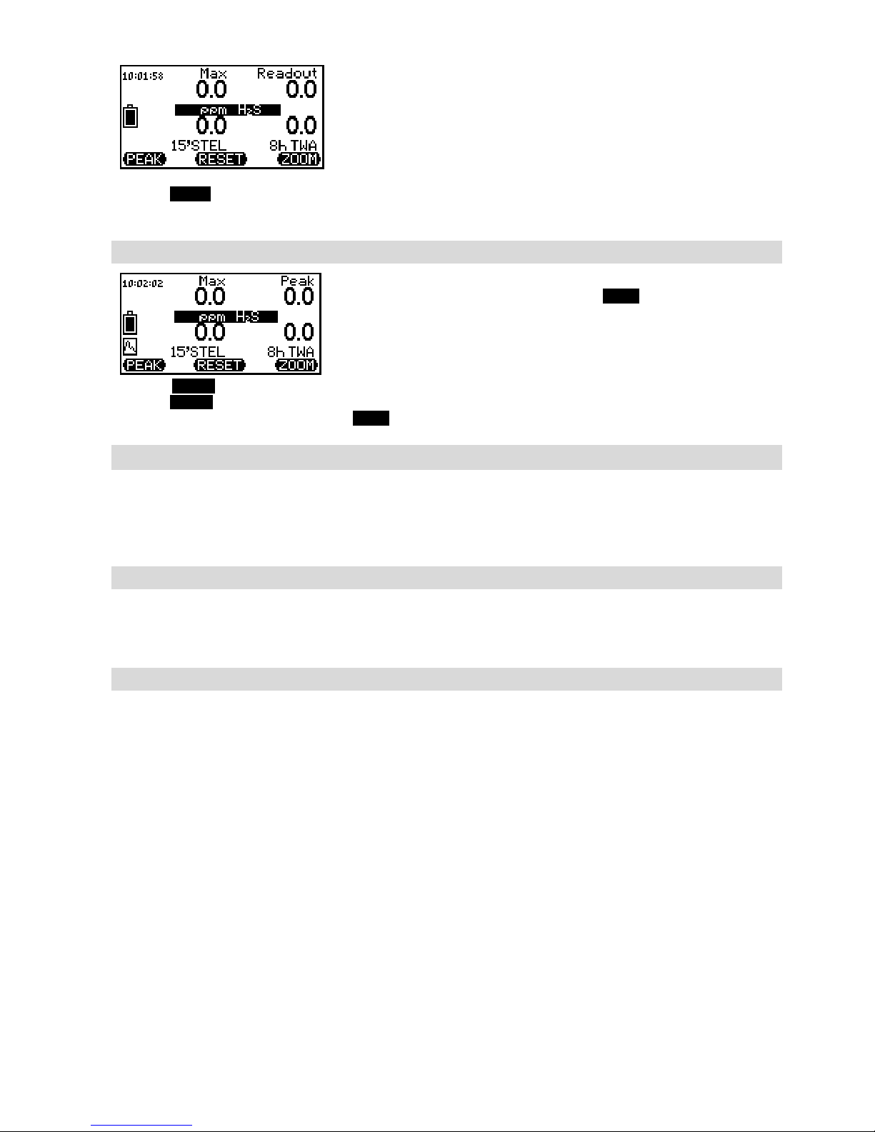
Example of zoom display for H
2
S:
Top left: Peak value
Top right: Current gas concentration
Bottom left: STEL value (15 minutes)
Bottom right: TWA value (8 hours)
Pressing ZOOM a certain time changes from one to the other zoom modes. After one zoom mode being
activated, the display returns back to normal mode after approx. 10 seconds.
Peak – Display of Peak Values
During peak mode (activation by left key PEAK) peak values can be
monitored and displayed. The display shows an animated symbol in the
left bottom corner. Within zoom display the peak value will be displayed
in the top right corner instead of the actual gas concentration.
Pressing RESET during peak mode, the peak memory will be reset to the current gas concentration.
Pressing RESET during zoom display, the peak memory and the peak value memory will be reset to the
current gas concentration. By pressing PEAK again, the peak mode is deactivated.
Turn On /Off Lights
The G460 is optionally available with a rechargeable battery pack with lights. The lights can be switched on
by keeping the left key pressed for approx. 3 seconds, and turned off by pressing this key shortly. The lights
are useful e.g. when the device is linked to a cord and let down into a sewer system. Using the lights can
prevent the device from being dipped into water.
Display Illumination
The display illumination is turned on for approx. 10 seconds whenever you hit any key. It turns off
automatically after that time. Should the battery or accumulator be almost exhausted, the display
illumination cannot be activated any longer.
Storing Measurement Data with the Data Logger
The measurement data can be stored in an integrated data logger or on a detachable micro SD card. A
special activation of the data storage is not necessary. With the internal data logger about 1800 events for
all measurement values and further information can be stored, containing date, time, location, alarms and
special events. Within the main menu under “data logger” different functions of the data storage can be set.
It provides a selection of the storage of average values, peak values or instantaneous values as well as the
storage interval from 1 second to 60 minutes. The default setting of storing is a loop memory. The oldest
event will be overwritten when the data loggers is full. The measurement data of the Microtector II can be
read on a PC by means of a charging adaptor, a USB-interface and the GfG-Interface software. The
configuration of the data logger can be changed with the interface program. Nearly an unlimited amount of
measuring points for all measurement values and other information can be stored on the micro SD card,
including date, time, location, user, alarm status, battery status and present device configuration. The
measurement data are stored as an average with an interval of one minute resp. five seconds in case of
alarm. Two text files are generated each month. The file *M.TEXT contains data from the measurement
operation and the file *C.TXT contains data from the charging processes. Depending on the intensity of use
and alarms being triggered, the files have a size of about 1-2 MB at the end of the month. With a 1GB micro
SD card data can be saved for a theoretic period of more than 40 years. The micro SD card can be removed
by switching the instrument off and opening the battery pack. Using an SD-card reader data can be read on
a PC or be displayed with a text editor or spreadsheet program. Data can be opened in Excel by using mouse
and performing drag & drop. After adjusting the width of the column a diagram of the records can be
generated. The micro SD-card must be formated with a FAT (FAT16) and not with the FAT32 file system.

11
Influence of Oxygen and Interfering Gases
It is to be considered, that the measurement of gas and/or vapour concentrations in the range below 100%
LEL cannot be done accurately, if the oxygen concentration at the same time is below 10 %-Vol.. In this
case the CC sensor suffers from a lack of oxygen, which is necessary for the “catalytic combustion”. If the
oxygen sensor detects such a low concentration, the display reads “????” instead of the LEL value. When the
oxygen concentration exceeds 10 %-Vol., the LEL value will be displayed correctly again. The EX-approval
does not cover the use of the detector in oxygen enriched atmospheres. Certain components, known as
„sensor or catalyst poisons“, may affect the signal behaviour of the CC sensor. The "sensitivity", i.e. the
capability of the sensor to give signals, is reduced. Components of this kind are e.g. sulphuric, lead or
silicone compounds.
Special Notes for LEL Monitoring
For LEL monitoring the G460 may use a catalytic combustion (CC) sensor. Due to this principle the G460
cannot distinguish between measurement values in the LEL range and those in the high Vol.-% range (e.g.
> 20 Vol.-% CH
4
). Concentrations of more than 110 % LEL might also damage this sensor. To prevent such
a damage, the sensor is turned off, when gas concentrations of more than 110 % LEL are measured. Only
pressing the key RESET and confirming the question “Fresh Air?” by means of key YES the sensor is turned
on again. Oxygen concentrations of less than 10 %-Vol. do not allow the CC sensor to correctly detect
combustible gases and vapours. The paragraph „Influence of Oxygen and Interfering Gases“ provides
additional information.
HI%-Measurement of Methane resp. Natural Gas
[#]
In standard detection mode methane (CH4) can be measured within a range of 0..100 %LEL by using either
a catalytic combustion sensor (CC) or an infrared sensor (IR). In this mode all gas alarm thresholds are
monitored. If the instrument is equipped with a special HI%-IR sensor (MK227-5 or MK231-5), monitoring of
higher ranges of up to 100 %-Vol. CH
4
is possible. By pressing the middle and left key simultaneously the
mode will be switched to HI%-range. In this mode no gas alarms will be monitored. Apart from deactivated
gas alarms also the confidence bleep and optionally the catalytic combustion sensor are deactivated. The
display shows in the left top corner the HI%-symbol. The measurement value of the infrared sensor is
shown in %-Vol. CH
4
and the position for the measurement values of the catalytic combustion sensor
remains blank. The pressure dependence of the IR sensor explained within the “Sensor Specifications” must
be noticed. If the gas concentration falls below 5 %-Vol. CH
4
the %LEL range can be re-activated by hitting
the middle and left key simultaneously. Gas alarm, confidence bleep and optionally catalytic combustion
sensor are re-activated as well.
Service Mode
Press the middle key (RESET) for approx. 5 seconds to activate the service mode. In the service mode the
G460 can be adjusted by changing of program parameters. Certain menu points require the access code
„0011“ to prevent accidental change of important functions by unauthorized persons. During the service
mode all alarms are deactivated. The main menu is the first menu point in the service mode.
Main Menu
The menu points of the main menu are:
1. Location (= Entering a location)
2. User (= Entering of identity)
3. Data logger (= Adjustment of data logger functions)
4. Signal (= Setting of confidence bleep intervals)
5. Service (= Starting the service menu)
6. AutoCal (= AutoCal adjustment with fresh air or with test gas)
7. Options (= Anti-Lazy-Battery, contrast, alarm volume)
8. Pump (= Information and status of the pump )
Menu control: The function of the key is explained by the display reading above the relevant key.
12
Left key ( = Scroll down
Middle key (SELECT) = Selection of marked menu point
Right key (DETECT) = Back to detection mode
Location – Entering a Location
From a deposited table one location out of hundred possible locations can be selected. The first two digits
stand for the number of the table entry. Except of the table entry “00” all other 99 entries can only be edited
by means of a PC. Within the table entry “00” up to 15 letters / figures can be entered, which will be stored
as “Location” on the G460.
If Location is selected by pressing the middle key (SELECT), the following reading is displayed:
During location selection a consecutive number is determined first:
EDIT = Confirming of consecutive number
EXIT = Back to main menu
= Changing of consecutive number
After confirming the consecutive number by pressing the left key (EDIT), the location entry will follow:
The function of the keys is as follows:
ABC = Change of symbol – moving forward in alphabetical order
<<>> = Enters the blinking letter or figure and moves the cursor
to the right
012= Change of symbol – moving back in alphabetical order
User – Entering User Name
From a deposited table one out of ten possible entries can be selected. The first two digits stand for the
number of the table entry. Except of the table entry “00” all other 9 entries can only be edited by means of a
PC. Within the table entry “00” up to 15 letters / figures can be entered, which will be stored as
“IDENTIFICATION” on the G460. Entry is completed automatically, when the cursor reaches the end mark
">". Entering the user name (ID) is done in the same way as entering the location.
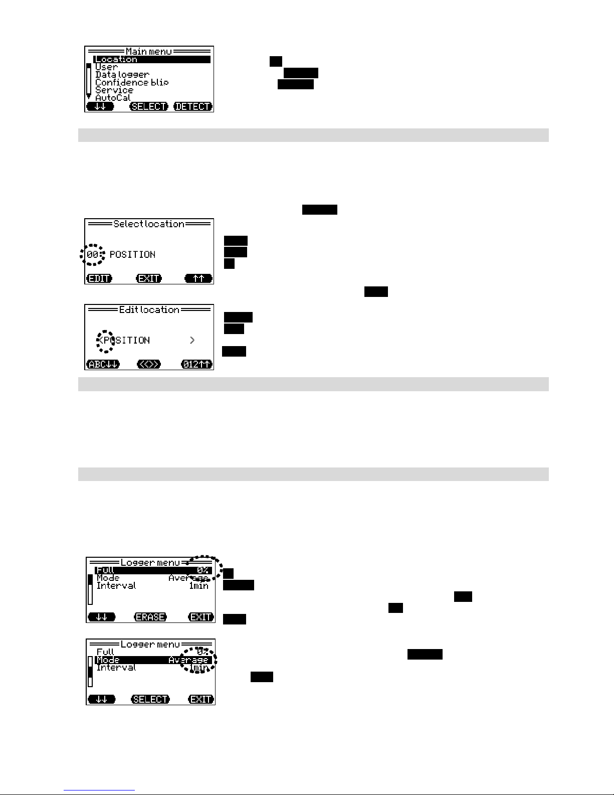
Data Logger Settings
Within the menu point “Data Logger“ different settings can be done:
Full - Deleting data from data logger (indication of storage occupancy)
Mode - Selection of instantaneous, average or peak value
Interval - Interval of data recording (adjustable from 1 second to 60 minutes)
Parameter Full shows the occupancy of the data logger.
= Scroll down to next parameter
ERASE = Deletes data. A security check is effected
“Delete data?” Confirm with the right key YES,
resp. deny with the left key NO.
EXIT = Back to main menu
If parameter Mode was selected with SELECT, instantaneous value,
average value or peak value (PEAK) can be chosen.
Press EXIT to return to the recorder menu. The selected mode will be
kept.
 Loading...