

GIG DS404 Operation Manual
Operations Manual
Docking Station DS404

2
GfG Products For Increased Safety
Congratulations!
You decided in favour of a high-technology product from GfG.
A good choice!
Our detectors are characterised by reliability, safety, best performance and
economic efficiency.
They comply with national and international directives.
This manual will help you to operate the detector quickly and safely.
Please take note of the operational hints before putting into operation!
For any questions please feel free to contact us.
Your
GfG Gesellschaft für Gerätebau mbH
Klönnestraße 99
44143 Dortmund, Germany
Tel.: +49(0)231 – 564 00-0
Fax: +49(0)231 – 564 00-895
E-mail: info@gfg-mbh.com
Internet: www.gasmessung.de

3
Table of Contents
Page
INTRODUCTION 4
For your Safety 4
Application and Purpose 4
Installing and Connecting the Docking Station 4
Connections and Control Elements of the DS404 5
Detector Adapter 6
CO2 Absorption Filter 6
HANDLING FEHLER! TEXTMARKE NICHT DEFINIERT.
Charging 7
Bump Test 7
Sensor Calibration 9
Data Storage/Data Transfer to a PC 11
SOFTWARE 12
Installation 12
Installation of the USB Driver 12
Configuration of the DS404 12
Connection 12
General 12
CO2 Filter 13
Gas Input 1 13
Test Times 13
Clock 14
Intervals 14
ANNEX 15
Care 15
Maintenance and Inspection 15
Troubleshooting 15
Accessories and Spare Parts 16
Technical Data 16
4
Introduction
For your Safety
In accordance with § 3 of the German Equipment and Product Safety Act (GPSG), this manual describ es the
intended use of the product and serves to avoid danger. It must be read and observed by all persons who
operate, servic e, maintain and inspect this product.
This detector can serve its intended purpose only if it is operated, serviced, maintained and inspected
according to the instructions given by GfG Gesellschaft für Gerätebau. The warranties given by GfG
Gesellschaft für Gerätebau mbH will be voided if the product is not operated, serviced, maintained and
inspected in accordance with GfG’s instructions.
The above does not alter statements regarding warranties and liabilities in the General Conditions of Sale
and Delivery of GfG mbH. Repairs may only be carried out by skilled or trained persons. Modifications and
changes to the product may only be carried out with the approval of GfG mbH. Unauthorised modifications
to the product result in the exclusion of any liability for possible damage. Only genuine GfG accessories may
be used together with the produc t. O nly spare parts approved by GfG mbH may be used for repa ir work.
Note: When using the docking station you have to remember that all gas detectors that are calibrated with
the station will be influenced. Incorrectly entered test gas concentrations will result in all gas detectors being
incorrectly cali b r a ted.
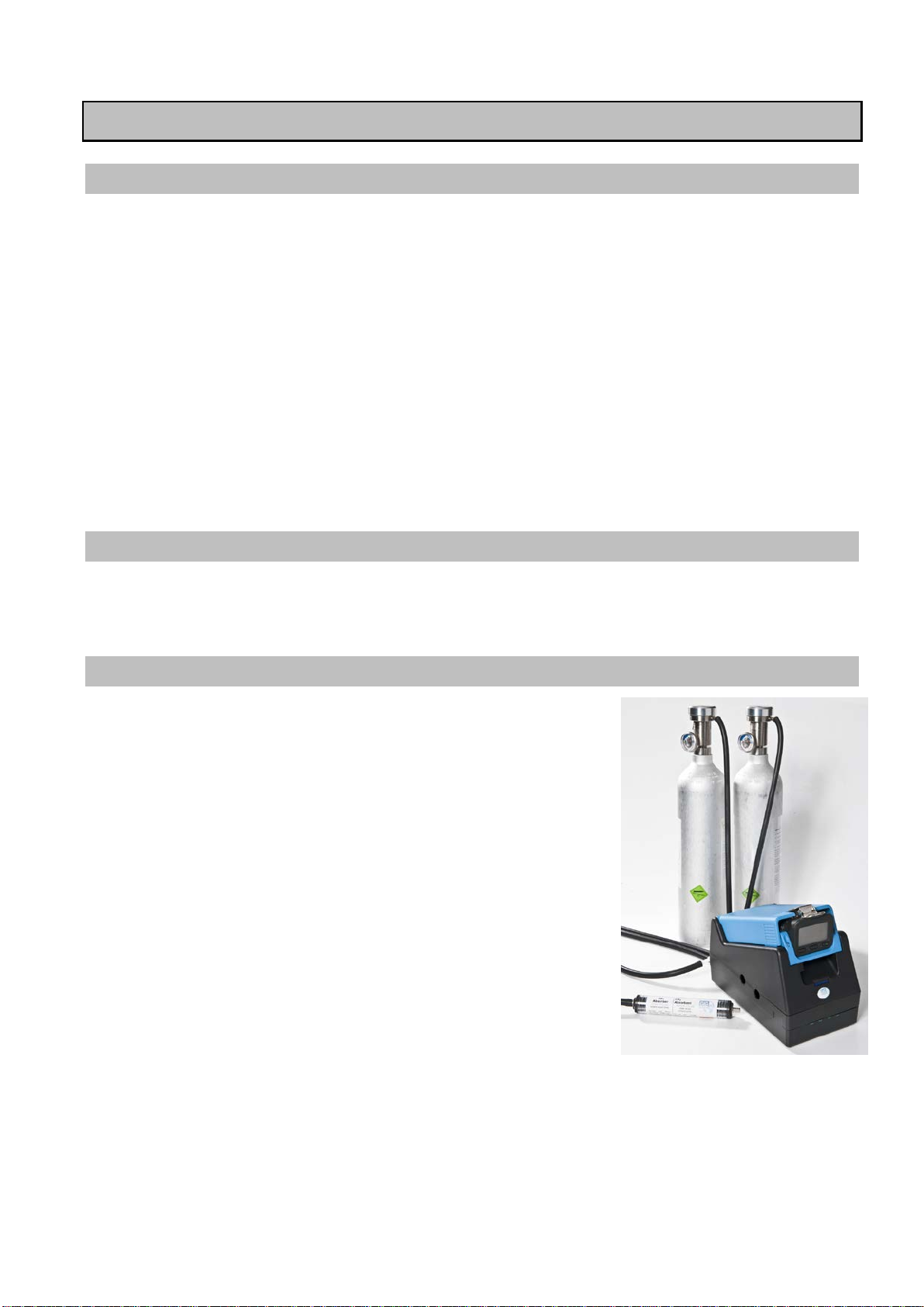
Application and Purpose
The Docking Station DS404 is an automatic test station with four test gas ports for carrying out function
tests ("bump tests") and for calibration of the zero point and sensitivity of the sensors of the Microtector II,
Microtector II I und Polytector III series gas detectors.
Installing and Connecting the Docking Station
During commissioning, the hoses and leads for fresh air supply, test gas
supply, gas discharge, pressure switch, mains power supply and PC
interface or interface to a further docking station must be connected to
the test station.
The docking station must be installed on a firm and even surface. The
gases must be supplied pressure-free. For direct gas tapping from test
gas cylinders, use the gas connection fittings listed in section
"Accessories and Spare Parts". During operatio n, the gas is drawn in by
the pump of the docking station. Ensure also that the test gas can leave
the docking station freely without pressure! If CO
tested or calibrated using the docking station, a CO
should be installed in the fresh air supply line (see chapter CO
absorption filte r ).
Ensure that the plug is installed on the T-piece of the fresh air supply
line or that it is conn ected to a further doc king station.
Up to two DS404 or three DS400 docking stations can be operated with
one DS400-PS1 power supply u nit. For this the DS404 or DS400 have to
be connected together using a double-sided jack plug.
During commissioning, the connections for gas supply, gas discharge,
pressure switch, mains power supply and PC interface or interface to a
further docking station must be made as shown in the figure in the
following chapter.
sensors are also to be
2
absorption filter
2
2
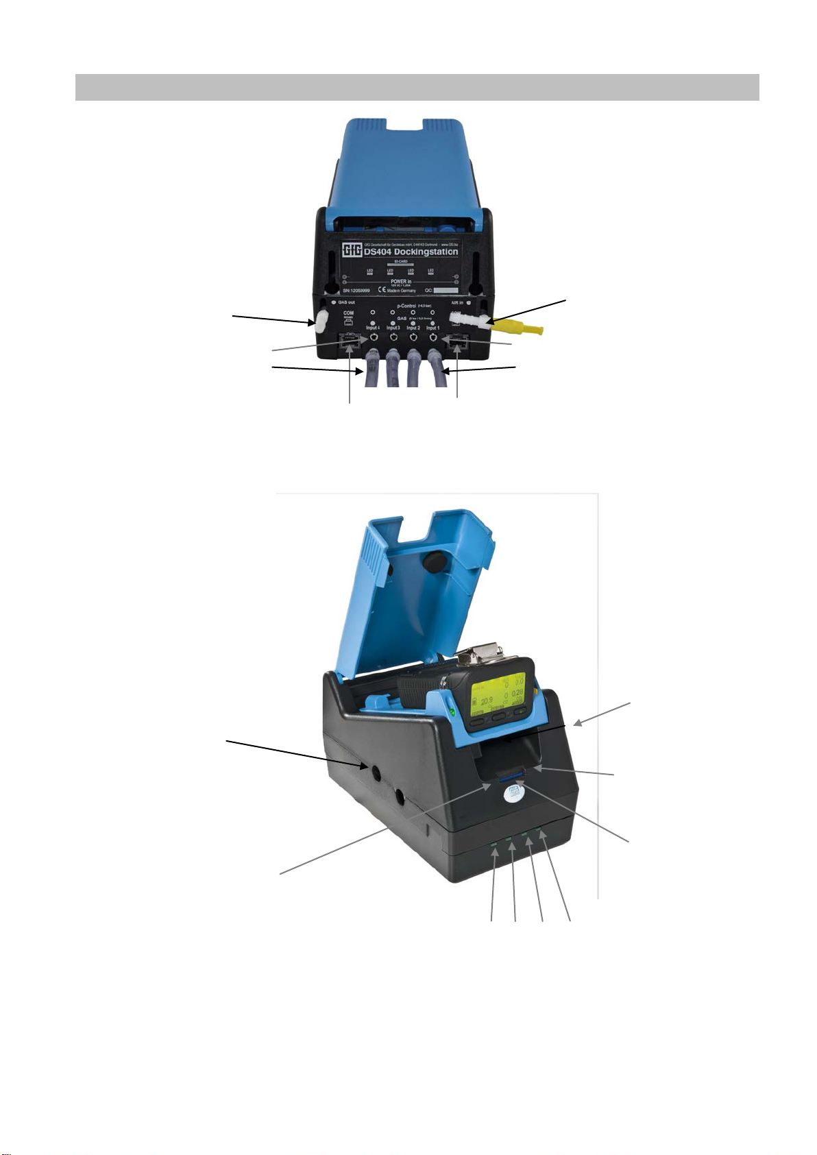
5
Zero gas/fresh air
Pressure switch –
Gas exhaust pipe
Pressure switch –
SD card
Red LED
Connection for
power
supply unit
Ports for RS485
Green LED
(on
the card slot)
Connection for
12
supply unit
1 2 3 4
Connections and Control Elements of the DS404
channel 4
Test gas supply –
channel 4
12 V DC
(on left side in the card slot)
channel 1
Display of active input
supply
V DC power
the right in
6
Three detector adapters are available for prepared docking stations. One version for devices without
Microtector III and Polytector III. The electric pump can remain on the
CO2-free zero gas is required particularly for the testing and
calibration of the CO
sensor zero point. As fresh air contains
approx. 500 ppm CO
can be removed using
a CO
is thereby absorbed by calcium
hydroxide (80
%) in the
follo
The absorber removes 1000 ppm
2,500 l of air.
This corresponds to a service life of approx.
minutes of
zero gas pump operation with one docking station. The DS404
calculates the service life on the basis of the flow rate and gives a
warning to replace the filter in good time. The filter gradually
changes colour to
G400-DIC1D for
Microtector II
without a pump
G400-DIC2D for
Microtector II with
attached pump
DIC888/999-B
for Microtector III
and Polytector II I
Detector Adapter
screwed on electric pump. A second version for devices with screwed on electric pump (G400-MP2) and a
third version for the detectors
device for all tests. All three device adapters can be used at the same time by the docking station as
charging cradle. To replace th e device adapter, the DS400 mus t be disc on nected from the power supply .
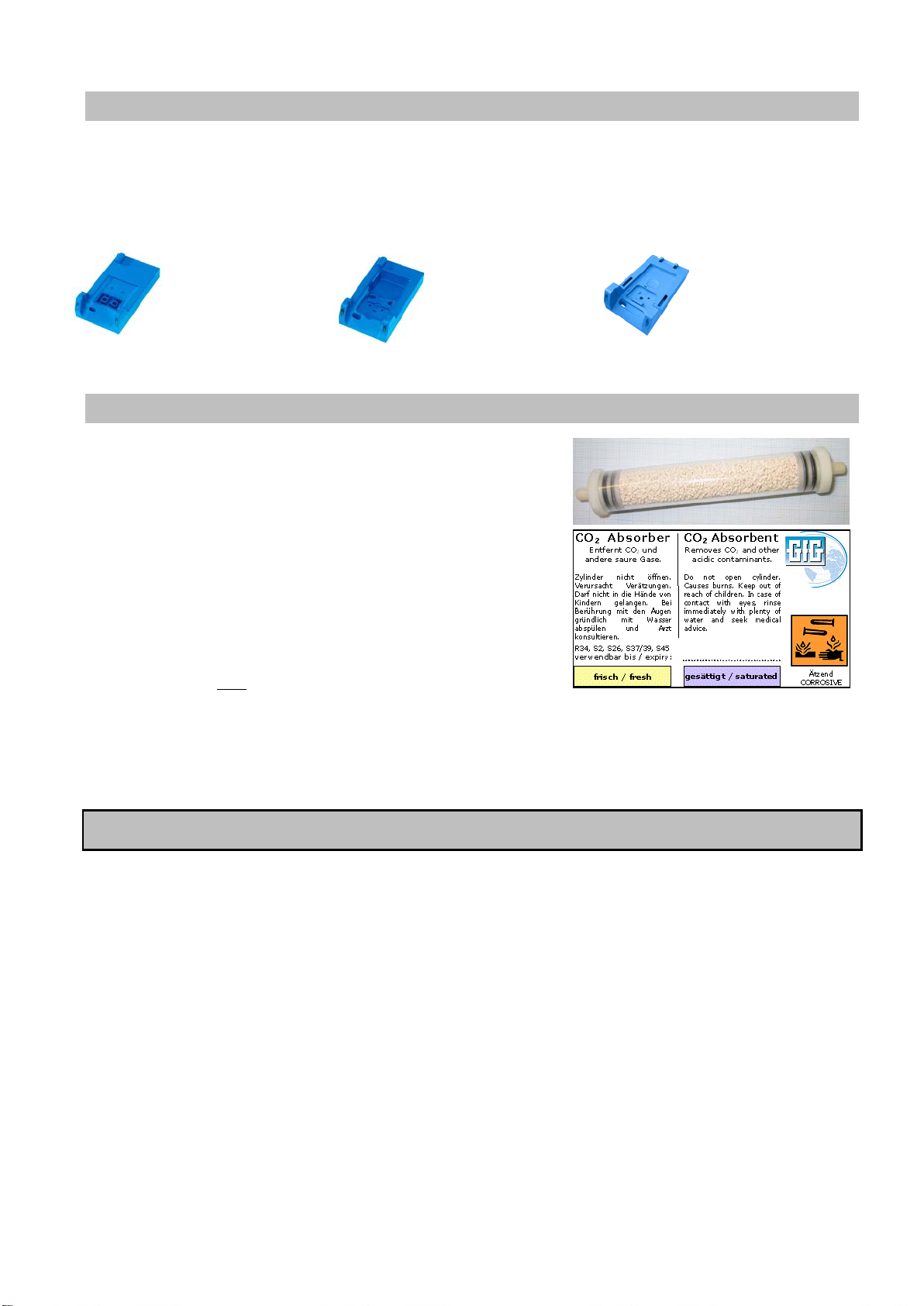
CO2 Absorption Filter
2
, the disturbing CO2
absorption filter. The CO2
2
wing reaction:
%) / sodium hydroxide (5 %) / H2O (15
2
CO2 + 2 NaOH Na2CO3 + H2O
Na2CO3 + Ca(OH)2 CaCO3 + 2NaOH
CO2 from appro x.
5,000
pale blue.
As water is also produced during the absorption process due to the chemical reaction, depending on the CO2
content of the air, this can have a min or influence on the setting of the sensor z e r o point.
Handling
The docking station is operated by means of the control ke ys of the gas detecto r . The status and tes t data
are output to the detector display . If a gas detector is inserted in to the docking station, the "Information",
"Function Test" or "AutoCal adjustment" options c a n be selected via softkeys on the gas detec tor.
Microtector II d evices can remain in the docking station for operation. De vices of the Microtector III and
Polytector II I s e r ies must be briefly rem oved from the ch a r g er to select the displayed operating opti ons, in
order to be able to operate the concealed keys. After pressing th e keys, the unit is placed back in the
charger. Under certain conditions, a "Firmware Update" can also be carried out using the docking station
when the gas detector is in the station . For this, there m ust be a newer version of a corresponding update
file on the SD card and the "Update" started by pressing the cor res ponding key.
In order to charg e a gas detector, it must be s witched off and placed in the docking s ta tion. If the detector is
placed into the docking station switched on, the necessary test or calibration will be started automatically
after 10 seconds. Within the 10 seconds you can override the automatic selection and start a function test or
calibration man ually.
 Loading...