

Page 1
GfG GESELLSCHAFT FÜR GERÄTEBAU MBH▐ KLÖNNESTRASSE 99▐ D-44143 DORTMUND▐ TELEPHONE +49 / (0) 2 31 / 5 64 00 –0 ▐ FAX +49 / (0) 2 31 / 51 63 13
[email protected] ▐ WWW.GASDETECTION.BIZ▐ AMTSGERICHT DORTMUND HR B 2742▐ CERTIFIED AS PER DIN EN ISO 9001:2000▐ ATEX QM CERTIFICATE
Operation Manual
CI21
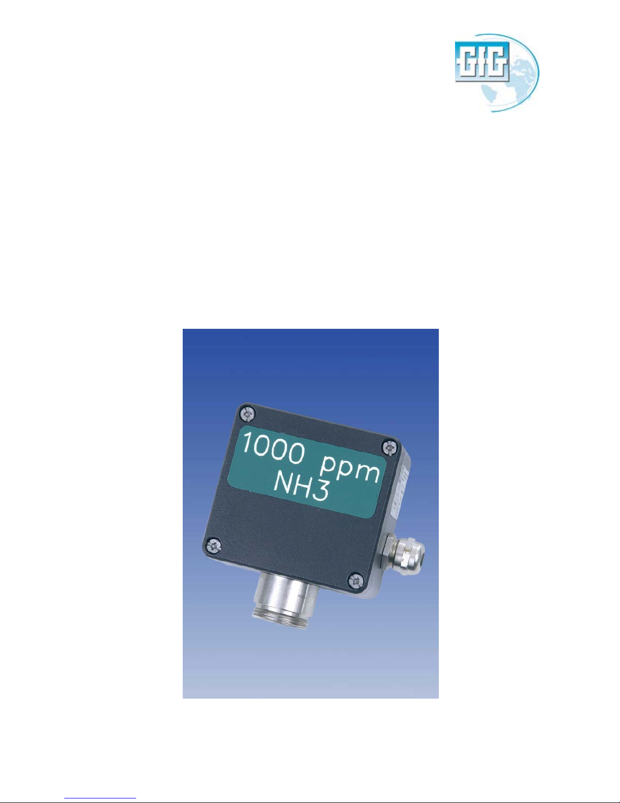
Transmitter for NH3
Page 2

Content
Page
For your Safety 3
General Description 3
Detection Principle 3
Operational Hints 4
Design 4
Mounting Position 5
Mounting 5
Installation of Electrical Connections 6
Putting into Operation 6
Check of Electrical Zeropoint 6
Check of Sensitivity 7
Service 8
Maintenance and Inspection 9
Trouble Shooting 9
Spare Parts 9
Accessories 9
Connection Diagram CI 21 Built-in Sensor 10
Connection Diagram CI 21 External Sensor 11
Technical Data 12
EC-Declaration of Conformity 13
Page 3
-3-
For your Safety
According to § 3 of the law about technical working media, this manual points out the proper use of the
product and serves to prevent dangers. As any piece of complex equipment, the GfG transmitter CI 21
will do the job designed to do, only, if it is used and serviced in accordance with the manufacturer's
instructions. Please protect yourself and your employees by following them. This manual must be
carefully read by all individuals who have or will have the responsibility for using and servicing this
product. The warranties made by GfG Gesellschaft für Gerätebau with respect to the product are voided,
if the adjustment of functions or parameters is changed without GfG Gesellschaft für Gerätebau’s
permission. They are also voided, if the product is not used and serviced in accordance with the
instructions in this manual. Failures or false alarms caused by interfering gases or electrical signals, are
not part of the warranty obligation. The above does not alter statements regarding GfG Gesellschaft für
Gerätebau's warranties and conditions of sale and delivery.
General Description
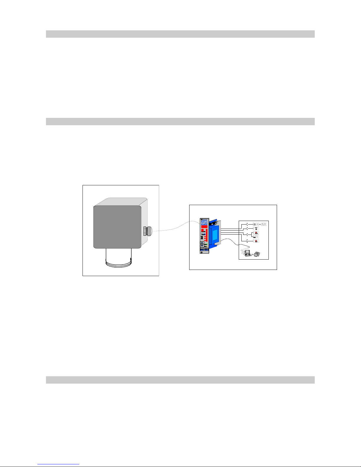
A fixed gas monitoring system consists of the transmitter (MWG) and a controller (GMA), which are
connected by means of cable. The transmitter converts the unit for the gas concentration into an
electrical signal and transmits it over the cable to the controller.
Fixed Gas Detection System
A
1
F
A
U
L T
A3 A
2
4
0
O N
F A U L T
6
02010
080
%
C H A N N E L
T Y P E L A B E L I N S I D E
TEST
Q
UTA2A3A
1
MEN
U
MEN
U
U
n
M
U
ou
N
M E N U
Detection
Evaluation
Warning
Fig. 1
The CI 21 is an "intelligent" transmitter. The comprehensive electronics allows easy operation and
maintenance and also increases the operational safety and accuracy. The CI 21 is characterized by the
following features:
Easy calibration at site.
Compensation of temperature effects.
Long sensor life.
Detection Principle
The CI 21 is operated with a Charge Carrier Injection sensor. A s long as there is no gas in the ambient
air, the internal resistance of the sensor is rather high. As soon as NH
3
(Ammonia) is adsorbed at the
sensor surface, the internal resistance is reduced. The change in resistance is the measure for the gas
concentration and is converted into a standardized current signal (0.2 .. 1 mA or 4 .. 20 mA) by the
integrated electronics. The Charge Carrier Injection sensor has proven a good long-term stability and,
because of the sensor design, a good selectivity.
Page 4
-4-
Operational Hints
According to national regulations gas warning devices have to be checked by a specialist for function
after installation but before being brought into service (putting into operati on). According to BGR 500,
Chapter 2.33, pt. 4.4 (testing of gas detection systems) as instructions of the BG-Chemie T021 (BGI
836).
Before shipment, the CI 21 passes a function and display test, being cal ibrated with suitable test gases.
This does not, however, overrule the obligation of putting into operation with test gas after
installation.
Design
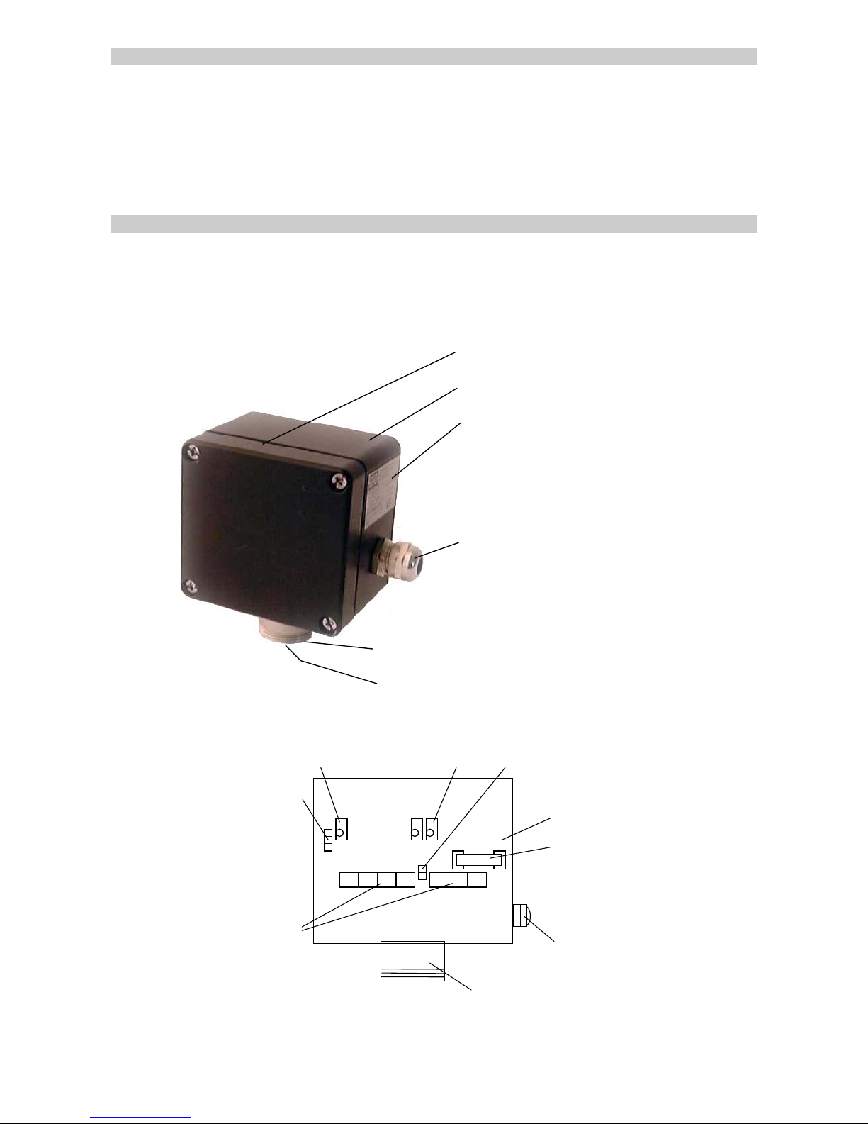
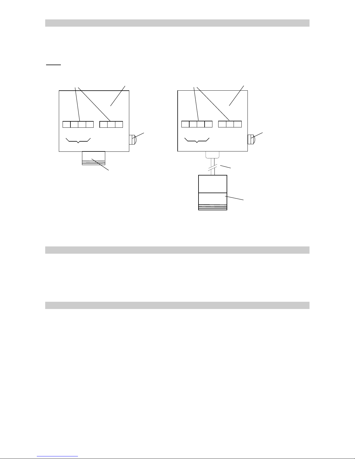
The design of the CI 21 is shown in fig. 2. The sensor is mounted in the sensor support (pos. 5). The gas
enters the sensor chamber through the diffusion inlet (pos. 6). The casing (pos. 2) includes a resin
encapsulated p.c.board with electronic components. The electronics convert the measurement signal into
the output of 0.2 .. 1 mA or 4 .. 20 mA, which is supplied to the controller by means of cable.
CI21 – Design
1. Casing top
2. Casing bottom
3. Type label
4. EMC cable gland (PG 11)
5. Sensor support
6. Diffusion inlet
Fig. 2
Test Contacts
Terminals
Sensor
EMC - PG 11
0 1 3 6 5 4
Fuse
Epoxy Resin
2
Jumper
Poti A
Poti 0
(option)
Poti C
+
0
-
Fig. 3 / Schematic
Page 5
-5-
Mounting Position
It is essential to exactly know the ambient conditions, which have to be taken into consideration before
deciding on the mounting position. To achieve representative measurement results, take care of:
the room ventilation,
the gas density, and
the danger highlights.
Install the CI 21 at a place where the gases pass the sensor even in case of bad ventilation. If necessary,
use a smoke cartridge to check.
Furthermore, take the following into consideration as well:
Ambient temperature,
Rain water, hose water, dripping water, condensation and
Dust in the atmosphere.
The CI 21 is to a great extent protected against the entering of water and dust (IP 54). Special
accessories are available to provide additional protection for very difficult condi tions. Please contact GfG
for detailed information.
!
Warranty may be voided, if the transmitter is exposed to ambient conditions which
were unknown to GfG during planning, production or delivery.
When deciding on the position for the transmitter, make sure that it is always accessible for service and
maintenance. It is recommended to mount the CI 21 with the sensor facing down to the floor. A different
mounting position, however, does not affect the sensor accuracy.
Mounting
For connecting the CI 21 refer to the connection diagram (also refer to the terminal diagram of your GMA
controller). For mounting the transmitter remove the four lock screws and l ift the casing top off. Fix the
casing by means of two screws through the relevant borings. The printed circuit board with electronic
components inside the casing is potted in epoxy resin. The optional potentiometer 0 is factory-set and
MUST NOT
be turned.
!
The CI 21 is not certified for use in hazardous areas
Page 6
-6-
Installation of Electrical Connections
Procurement of cable and electrical connections must be done by a specialist only, obeying the applicable
regulations. A shielded 3-core cable has to be used (e.g. LIYCY 3 x 1.5 mm
2
). The cross section of the
cable depends on the cable length. For short distances (max. 200 m) it may be sufficient to use
0.75 mm
2
instead of 1.5 mm2.
Note:
Shielding is effected over the EMC cable screwing.
red
Sensor
yellow
Voltage
Supply
Ground
Resin
Terminals
Sensor
EMC-PG 11
0 1 2 3 6 5 4
Signall
red
g
reen
Sensor
Voltage
Supply
Ground
Resin
Terminals
EMC-PG 11
0 1 2 3 6 5 4
Signall
External Sensor
Connecting Wire, max. 2 m
g
reen
brown
white
blue
Fig. 4
The supply voltage for the transmitter (terminal 4) is 10 .. 32 V DC.
Once the installation is completed, close the casing top and fix it with the screws.
Putting into Operation
Once the CI 21 is installed, a skilled person can put it into operation. Before shipment, the CI 21 has
been calibrated and tested after a specific warm-up time for several days. When connecting to a
controller (power supply) you should allow approx. 15 - 30 minutes to warm-up the Charge Carrier
Injection sensor before checking the sensitivity. Should you notice that a re-calibration is required, allow
an extended warm up period of about 4 hours. In case you replace the sensor, adjust the jumper of
the transmitter according to the specification on the new sensor.
Check of Electrical Zeropoint
The CI 21 is calibrated and tested before shipment. Certain deviations, however, are possible due to
transport, mounting and ambient conditions. According to “UVV Gase” only experts are permitted to do
the testing.
Inside the CI 21 there are two test contacts (fig. 3) to check the electrical output signal. The voltage at
the test contacts can be measured by means of a voltmeter.
After the warm-up time of approx. 30 minutes, the signal must be approx. 200mV for zero gas *. This
corresponds to an output current of 0.2 mA (0.2 .. 1 mA interface) respectively 4 mA (4 .. 20 mA
interface). In case of deviation it is possible to re-adjust the value by turning potentiometer A.
Alternatively, for example when using a GMA controller, you can check the transmitter signal at the
controller. After the warm-up time of approx. 30 minutes, you can read the zeropoint voltage at the
controller resp. check with a voltmeter (please read the operation manual of your GMA controller). In
case of deviation you can correct it at the controller.
Page 7
-7-
Check of Sensitivity
To check the sensitivity of the CI 21 fix a calibrati on adapter to the diffusion inlet of the transmitter. Then
select a suitable test gas, taking into consideration, which gas has been used for initial calibration of the
transmitter. You can see this information from the test report. The test gas concentration should be at
least 20 % above the second alarm threshold. The basic adjustment can be seen from the test report.
Use a multimeter to check the output signal by measuring the voltage at the test contacts. The voltage is
proportional to the output current. 200mV correspond to an output current of 0.2 mA (0.2 .. 1 mA
interface) resp. 4 mA (4 .. 20 mA interface). 1000mV correspond to an output current of 1 mA
(0.2 .. 1 mA interface) resp. 20 mA (4 .. 20 mA interface).
In case of deviation you can correct the value by turning potentiometer C.
Alternatively, for example when using a GMA controll er, you can check the transmitter signal at the GMA.
After the warm-up time of approx. 30 minutes you can read the signal voltage at the controller or check
it with a voltmeter (please read the operation manual of your GMA). Should you notice a deviation, you
can correct it at the GMA.
!
Do not use a test gas with a balance of nitrogen.
* In this case, zero gas is not fresh air but test gas with 30 ppm NH
3
in air
Page 8
-8-
For measurement accuracy it is important to set the calibration point for the second alarm threshold
accurately.
When using dry test gas a slower response time of the sensor has to be taken into account.
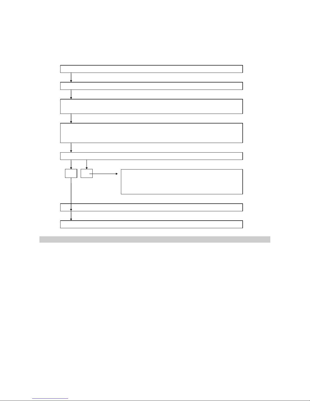
Adhere to the following procedure to check the sensitivity:
Suppress alarm transmission.
Screw calibration adapter onto transmitter.
Supply test gas to CI21 without pressure and
with a flow rate of approx. 0.5 l/min.
Within about 2-5 minutes a voltage corresponding to the gas concentration must
be measured at the test contacts.
Alternatively the calibration can be checked at the display of the GMA controller.
Is the measured value equivalent to the calibration curve?
Re-adjust calibration by turning potentiometer C.
Alternatively: Re-adjust calibration point at GMA
controller. Please refer to the operation manual of
your GMA.
Disconnect test gas and calibration adapter.
Disconnect alarm suppression.
Service
According to the German "Regulation for Explosion Protection", "UVV-Gase" and DIN 31051, service
stands for maintenance, inspection and repair of gas warning equipment. Regulation T023 of "BG
Chemie" describes the relating measures, among others requesting a regular function check.
This function check means:
Check with alarm gas concentration
Check of zeropoint and sensitivity (calibration)
Check of response time
Check of gas sampling and gas processing system (if any)
Check of alarm signal activation
Check of failure alarm
The check must be done by an expert, who has to report the result in written form. Generally the
function check intervals should not exceed 16 weeks. The function check shall be done before putting the
system into operation, and it should be repeated at least once a year.
no yes
Page 9
-9-
Maintenance and Inspection
With maintenance and inspection the proper and planned status of the gas detection system is controlled.
The CI 21 does not require special maintenance, nevertheless a few points should be obeyed.
Depending on the ambient conditions, gas detection systems may show a different behaviour. Therefore,
it is important to perform a visual check every day, particularly during the first few days after putting into
operation (see T023).
Check of pump assembly and gas processing system (if any).
Check of gas supply for soiling (for correct measurement the gas supply to the sensor must not
be blocked).
Sensors are subject to ageing and exhausting processes. Depending on their type and on their
exposure to gas they are more or less used. A sensitivity check can only be done with a suitable
test gas after certain periods of time. The sensitivity calibration is an expert calibration and is
usually performed by GfG service or by authorized persons.
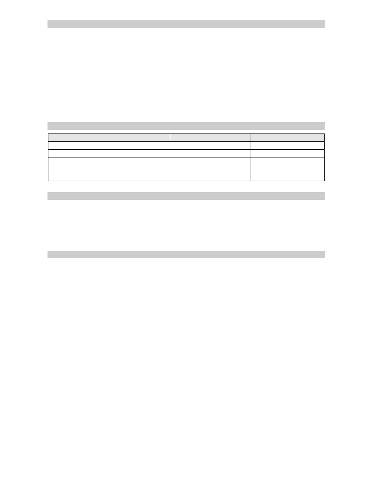
Trouble Shooting
Failure Reason Solution
Zeropoint cannot be adjusted Faulty sensor Replace sensor
Full scale value cannot be set Faulty sensor Replace sensor
Output current has fallen to 0 mA Blown fuse
Defective electronics
Cable cut
Replace fuse
Replace p.c.board
Re-fix connection
Spare Parts
Part No.
Casing Top 2211301
Spare Sensor/built-in 2211401
Spare Sensor/external 2212401
In case you replace the sensor, adjust the jumper inside the transmitter according to the
specification on the new sensor.
Accessories
Part No.
Calibration Adapter 2000209
Page 10
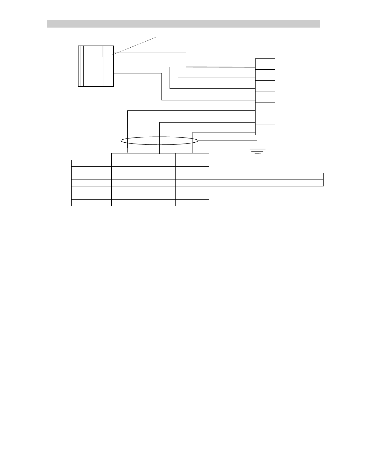
-10-
Connection Diagram CI 21 Built-in Sensor
Built-in Sensor
MK 378-6
red
0
red
1
green
2
yellow
3
white
6
green
5
brown
4
0.2-1 mA GND 20V / 24V
GMA300 2 1 5
GMA011 2 1 5
GMA100 2 1 5 with motherboard from 1997 (blue)
GMA100 2 0 3 with motherboard until 1996 (no colour)
GMA101 2 1 5
GMA41 30 29 28
GMA81 (A) 3 2 1
Connect shield to
Cable Gland
Page 11
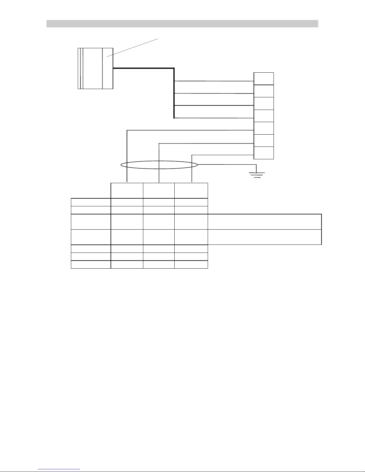
-11-
Connection Diagram CI 21 External Sensor
External Sensor
MK 378-5
green
0
brown
1
white
2
blue
3
white
6
green
5
brown
4
0.2-1
mA
GND 20V /
24V
GMA300 2 1 5
GMA011 2 1 5
GMA100 2 1 5 with motherboard from 1997
(blue)
GMA100 2 0 3 with motherboard until 1996 (no
colour)
GMA101 2 1 5
GMA41 30 29 28
GMA81 (A) 3 2 1
Connect shield to
Cable Gland
Page 12

-12-
Technical Data
Transmitter CI21
Type: CI21
Sensor Type: MK 378-5 (external) or MK 378-6 (built-in)
Gas: Ammonia, NH3
Standard range: 200ppm, 1,000ppm or 10,000ppm
Gas Supply: Diffusion
Detection Principle: Charge Carrier Injection (CI)
Supply Voltage: 10 ... 32 V DC
Output Current:
0.2 ... 1mA (4k) or 4 ...20mA (200)
Response Time t
: < 8 s
Typical Sensor Life: > 2 years
Climate Conditions
Temperature: -30 ... +55 °C
Humidity: 0 … 99 % r. h., non condensing
Pressure: 920 ... 1100 hPa
Casing
Material: Aluminium
Protection: IP 54
Cable Gland: PG 11, for cable size 3 x 1.5 mm
2
Transmitter Cable: 3 core shiel ded cable
e.g. LiYCY 3 x 1.5 mm2
Dimensions: 100 x 100 x 57 mm (WxHxD)
Weight: approx. 370 g
Worldwide Supplier of Gas
Detection Solutions
Gesellschaft für Gerätebau mbH
P.O.Box 440164, D-44143 Dortmund
Phone: +49-231-56400-0
Fax: +49-231-516313
E-Mail: [email protected]
Internet: www.gfg-mbh.com
18400010.doc Edition 16. Juli 2009
We reserve the right of modification
Page 13
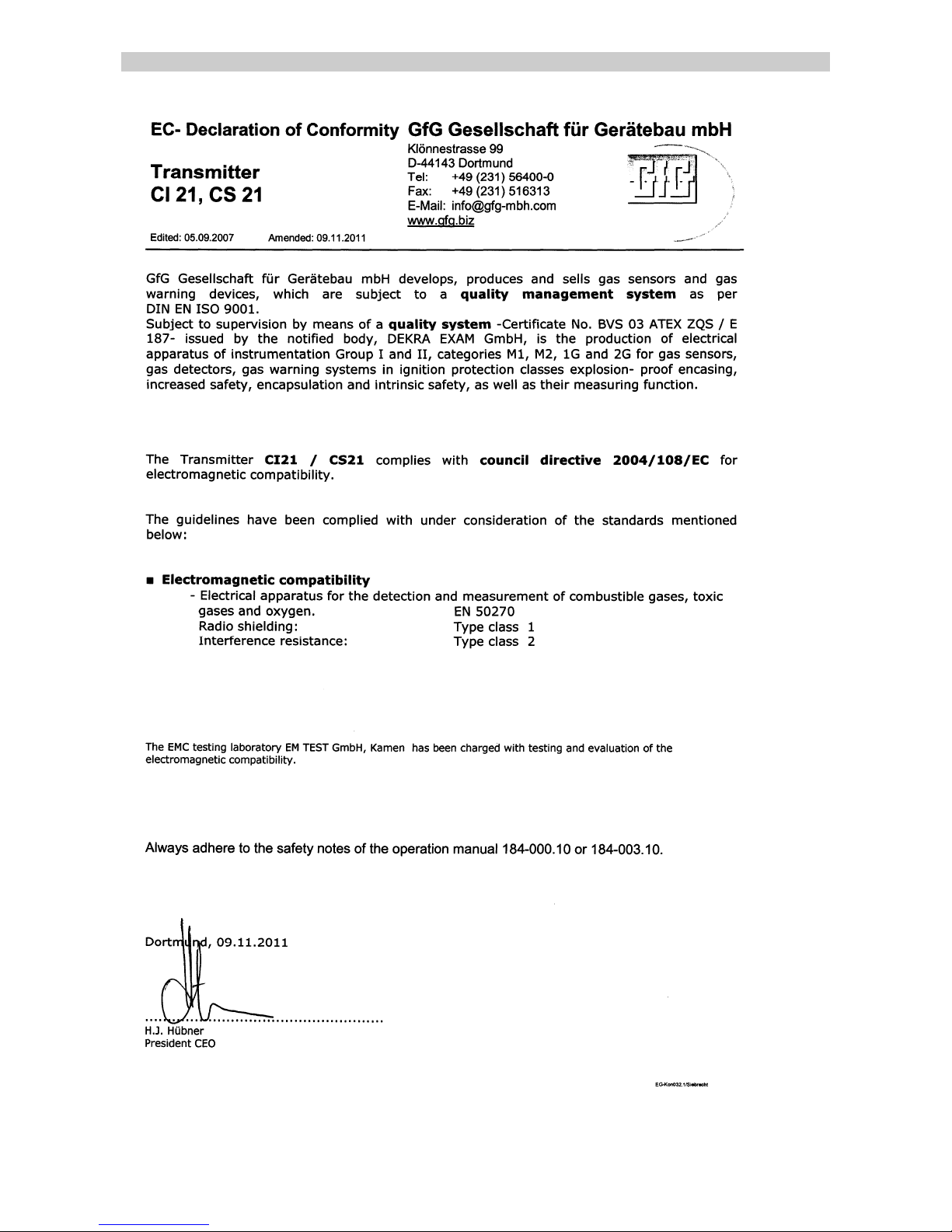
-13-
EC-Declaration of Conformity
 Loading...