

Giden M880, M840 User Manual
M880/M840
User`s Manual
©2006, GIDEN Electronics Russia (www.giden.ru)
M880/M840
Parameters
Min. Typi cal Max. Unit
Peak Output Current 2.8,/1.4 - 7.8,/3.9 Amps
Supply voltage +24 +68 +90 VDC
Logic signal current 7 10 16 mA
Pulse input frequency 0 - 300 Khz
Isolation resistance 500 M
Ω
MM888800//MM884400 HHiigghh PPeerrffoorrmmaannccee MMiiccrroosstteeppppiinngg DDrriivveerr VV11..2
2
MM888800//MM884400 HHiigghh PPeerrffoorrmmaannccee MMiiccrroosstteeppppiinngg DDrriivveerr VV11..2
2
Table of Contents
1. Introduction, Features and Applications ···································································2
2. Specifications and Operating Environment ······························································3
3. Driver Connectors P1 and P2 ···················································································4
4. Control Signal Connector (P1) Interface ····································································5
5. Driver Connection to Step Motors ············································································6
6. Power Supply Selection, Driver Voltage and Current Selection ··································10
7. Selecting Microstep Resolution and Driver Current Output········································12
8. Protection Functions ··································································································14
9. Connection Diagram for Driver, Motor, Controller ····················································14
10. Control Signal Waveform and Timing ······································································ 15
Appendix: Limited Warrenty ·························································································16
1. Introduction, Features and Applications
M880/M840 are high performance microstepping drivers based on the most advanced technology
in the world today. They are suitable for driving any 2-phase and 4-phase hybrid step motors. By
using advanced bipolar constant-current chopping technique, they can output more speed and
power from the same motor, compared with traditional technologies such as L/R drivers. Its 3-state
current control technology allows coil current to be well controlled, with relatively small current
ripple and results in less motor heating.
Features of this driver
High performance, low cost
Supply voltage up to +90VDC, current to 7.8A for M880; 3.9A for M840.
Inaudible 20khz chopping frequency
TTL compatible and optically isolated input signals
Automatic idle-current reduction
Mixed-decay current control for less motor heating
14 selectable resolutions in decimal and binary
Microstep resolutions up to 50,000 steps/rev
Suitable for 4,6,8 lead motors
Over-current, over-voltage protection
Small size (119 x 97 x 48mm for M880, 119 x 97 x 31mm for M840)
Applications of this driver
Suitable for a wide range of stepping motors of size Nema 34 and 43, and usable for various kinds
of machines, such as X-Y tables, labeling machines, laser cutters, engraving machines, and
pick-place devices, particularly useful in applications with low vibration, high speed and high
precision requirements.
2. Specifications and Operating Environment
Electric Specifications (T
j =
25)
Operating Environment and Parameters
Cooling Natural cooling or forced convection
Spac e Avoid dust, oil frost and corrosive gas
Temperature 0° 50
Humidity 40 90%RH
Environment
Vibration
5.9m/s2Max
Storage Temp. -20 65
Weight Approx. 440g (15.50 oz) / M880;330 g (11.60 oz) / M840
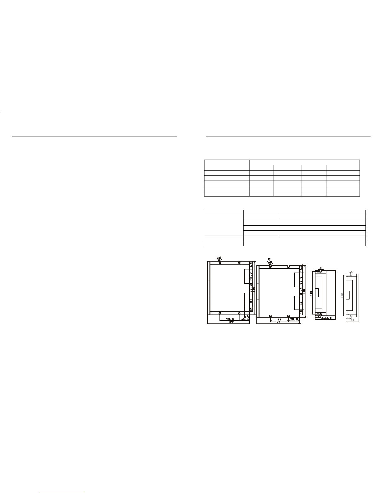
Mechanical Dimensions (unit=mm, 1 inch = 25.4 mm)
Side Vie
w
Side Vie
w
M880 Front View M840 Front View M880 M840
(with heatsink) (without heatsink)
Figure 1: Mechanical dimensions
2 3
Pin No. Signal Functions
1 Gnd DC power ground
2 +V
DC power supply, +18VDC +80VDC, Including
v
oltage fluctuation and EMF voltage.
3, 4 Phase A Motor coil A (leads A+ and A-)
5, 6 Phase B Motor coil B (leads B+ and B-)
Pin No. Signal Functions
1 Pul
(+5V
)
2 Pul(pulse)
Pulse signal: in single pulse(PUL/DIR) mode, this input
represents pulse signal, effective for each upward –
rising edge; in double pulse mode (CW/CCW) this input
represents clockwise(CW)pulse. For reliable response,
p
ulse width should be longerthan 3∝s.
3 Dir(+5V)
4 Dir(Dir)
Direction signal: in PUL/DIR mode, this signal has
low/high voltage levels, representing two directions of
motor rotation; in CW/CCW mode (set by inside jumper
JPI), this signal is counter-clock (CCW) pulse, effective
on each rising edge. For reliable motion response,
direction signal should be sent to driver 5
∝
s before the
first
p
ulse of a motion direction reversal.
5 Ena+(+5V)
6 Ena- (Ena)
Enable signal: this signal is used for enable/disable, high
level for enabling driver and low level for disabling
driver. Usually left unconnected(enabled).
MM888800//MM884400 HHiigghh PPeerrffoorrmmaannccee MMiiccrroosstteeppppiinngg DDrriivveerr VV11..2
2
MM888800//MM884400 HHiigghh PPeerrffoorrmmaannccee MMiiccrroosstteeppppiinngg DDrriivveerr VV11..2
2
3. Driver Connectors, P1 and P2
The driver has two connectors, P1 for control signals, and P2 for power and motor connections.
The following is a brief description of the two connectors of the driver. More detailed descriptions
of the pins and related issues are presented in section 4, 5, 9.
Control Signal Connector P1-pins
Power connector P2 pins
Remark : PUL/DIR is the default mode, under-cover jumper JP1 can be used to switch to
CW/CCW double-pulse mode.
Selecting CW/CCW and PUL/DIR Mode
There is a Jumper JP1 inside the driver specifically for the purpose of selecting pulse signal mode.
1. JP1 open collector mode is PUL/DIR mode, which is the default factory setting;
2. J1 open collector and J2 short circuit mode is CW/CCW mode; as following diagram:
4
Remark: Please note motion direction is also related to motor-driver wiring match.
Exchanging the connection of two wires for a coil to the driver will reverse motion
direction. (for example, reconnecting motor A+ to driver A- and motor A- to driver A+ will
invert motion direction).
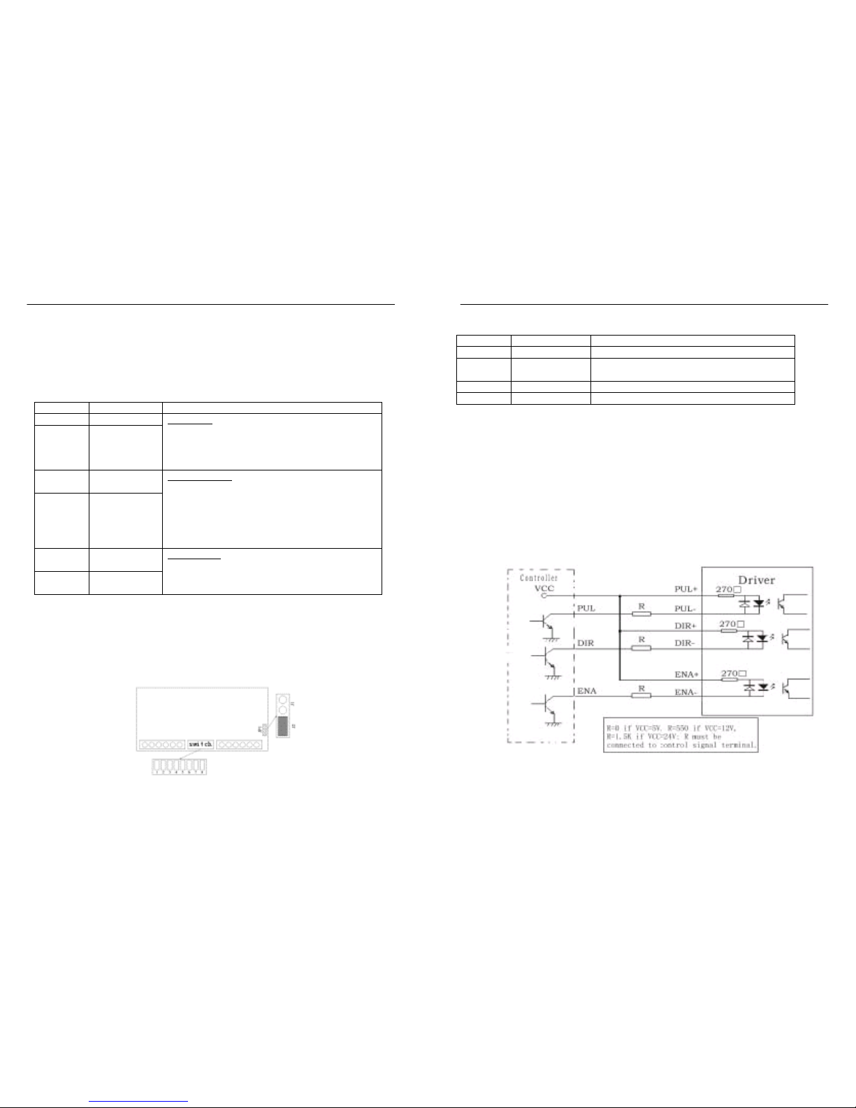
4. Control Signal Connector (P1) Interface
This driver uses differential inputs to increase noise immunity and interface flexibility.
Single-ended control signals from the indexer/controller can also be accepted by this interface. The
input circuit has built-in high-speed opto-coupler, and can accept signals in the format of line
driver, open-collector, or PNP output. Line driver (differential) signals are suggested for reliability.
In the following figures, connections to open-collector and PNP signals are illustrated.
Open-collector signal (common-anode)
5
 Loading...