

Giddings Lewis MMC Hardware Manual

MMC for PC
Hardware Manual
Part Number M.1300.7171
Version 1.0
TM
Giddings & Lewis
Controls, Measurement and Sensing

NOTE
Progress is an on-going commitment at Giddings & Lewis. We continually strive to offer the most
advanced products in the industry; therefore, information in this document is subject to change without
notice. The illustrations and specifications are not binding in detail. Giddings & Lewis shall not be
liable for any technical or editorial omissions occurring in this document, nor for any consequential or
incidental damages resulting from the use of this document.
DO NOT ATTEMPT to use any Giddings & Lewis product until the use of such product is completely
understood. It is the responsibility of the user to make certain proper operation practices are
understood. Giddings & Lewis products should be used only by qualified personnel and for the
express purpose for which said products were designed.
Should information not covered in this document be required, contact the Customer Service
Department, Giddings & Lewis, 660 South Military Road, P.O. Box 1658, Fond du Lac, WI 54936-
1658. Giddings & Lewis can be reached by telephone at (920) 921–7100.
M.1300.7171
Release 0201
© 2001 Giddings & Lewis, LLC
Windows 95, 98, NT, Microsoft, and MS-DOS are registered trademarks of Microsoft Corporation.
Pentium and PentiumPro are trademarks of Intel Corporation.
PiC900, PiCPro, MMC, MMC for PC, PiCServoPro, PiCTune, PiCProfile, LDO Merge, PiCMicroTerm and PiC Programming
Pendant are trademarks of Giddings & Lewis, LLC

Table of Contents MMC for PC Hardware Manual
1 Safety Precautions ...................................................................................................
1.1 System Safety .................................................................................................. 1
1.1.1 User Responsibility ............................................................................. 1
1.1.2 Safety Instructions ............................................................................... 1
1.2 Safety Signs ..................................................................................................... 2
1.3 Warning Labels ................................................................................................ 3
1.4 Safety First ....................................................................................................... 4
1.5 Safety Inspection .............................................................................................. 4
1.5.1 Before Starting Operations .................................................................. 4
1.6 After Shutdown ................................................................................................ 4
1.7 Operating Safely .............................................................................................. 4
1.8 Electrical Service & Maintenance Safety ........................................................ 5
1.9 Safe Cleaning Practices ................................................................................... 6
2 Introduction
..................................................................................................................... 7
2.1 Computer Workstation Requirements ............................................................. 8
2.1.1 Recommendations for MMC for PC Controller .................................. 8
2.2 Major Components .......................................................................................... 9
2.2.1 SERCOS Board ................................................................................... 9
2.2.2 Analog Servo Board ............................................................................ 10
2.2.3 Analog Servo Interface Unit (ASIU) .................................................. 13
2.2.3.1 ASIU Components ................................................................ 14
2.2.3.2 ASIU Axis I/O ...................................................................... 15
3 Installation of the MMC for PC Board and Software Suite
................................. 17
3.1 Installing the MMC for PC Board ................................................................... 17
3.2 Installing the Software Suite ............................................................................ 20
3.3 Installing the Support Software ....................................................................... 20
3.4 Removing the Software Suite .......................................................................... 30
4 Installing the ASIU Module
.......................................................................................... 31
4.1 Mounting Procedure for the ASIU ................................................................... 31
5 Power and Environment Requirements
.................................................................... 33
5.1 General Power and Environment Requirements .............................................. 33
5.2 ASIU Control Cabinet Specifications .............................................................. 33
5.3 Power Distribution for External Power Supply ............................................... 34
5.3.1 MMC for PC Board External Power Supply Distribution .................. 34
5.3.2 ASIU External Power Supply Distribution ......................................... 35
5.4 24V Power Supply Sizing ................................................................................ 37
5.4.1 MMC for PC Board 24V Power Supply Sizing .................................. 37
5.4.2 ASIU Power Supply Sizing ................................................................. 37
5.5 Grounding the System ..................................................................................... 40
5.6 Controlling Heat Within the System ................................................................ 41
5.7 Handling MMC for PC System Components .................................................. 42
1
GIDDINGS & LEWIS MMC for PC Hardware Manual TOC-1

6 Wiring Guidelines - MMC for PC to Application ...............................................
6.1 Recommended Signal Separation .................................................................... 43
6.2 Differential Devices for Analog and Encoder Signals Connected to the ASIU 46
7 MMC for PC Setup Procedures
.................................................................................. 47
7.1 Preparation for Maintenance or Setup ............................................................. 47
7.2 Connecting the MMC for PC System .............................................................. 49
7.2.1 Connecting the MMC for PC Board to an Application ....................... 49
7.2.2 Connecting the ASIU to an Application ............................................. 49
7.3 Connecting an ASIU Network ......................................................................... 50
7.4 Troubleshooting the MMC for PC Battery ...................................................... 51
8 Connections to External Devices
................................................................................ 53
8.1 Connections to External Devices - MMC for PC ............................................ 53
8.1.1 Optional External Power and Keyswitch Connections ....................... 53
8.1.2 Block I/O Port ..................................................................................... 54
8.1.3 Motion Control Connections for MMC for PC SERCOS Board ........ 55
8.1.3.1 SERCOS Receive and Transmit Ports .................................. 55
8.1.4 Motion Control Connections for MMC for PC Analog Servo Board . 56
8.1.4.1 ASIU Connector ................................................................... 56
8.2 Connections to External Devices - ASIU ........................................................ 57
8.2.1 General I/O Port .................................................................................. 57
8.2.2 Power Connection ............................................................................... 60
8.2.3 Axis Connectors .................................................................................. 61
8.2.4 Auxiliary I/O Connector ...................................................................... 66
9 MMC for PC Diagnostics
............................................................................................. 71
9.1 Description of MMC for PC Diagnostic Symbols ........................................... 73
9.1.1 Scan ..................................................................................................... 73
9.1.2 Access .................................................................................................. 74
9.1.3 Battery ................................................................................................. 74
9.1.4 Diagnostic ............................................................................................ 75
9.1.5 Diagnostic Error Text .......................................................................... 75
9.1.6 Connection Status ................................................................................ 76
9.1.7 Status Unknown .................................................................................. 77
10 ASIU Diagnostics
............................................................................................................ 79
10.1 Power-On Diagnostics ..................................................................................... 79
10.1.1 Power LED .......................................................................................... 79
10.1.2 Scan LED ............................................................................................ 79
10.1.3 Diagnostic LEDs ................................................................................. 79
10.2 Run-Time Diagnostics ..................................................................................... 80
11 Troubleshooting the MMC for PC Battery
.............................................................. 81
43
TOC-2 MMC for PC Hardware Manual GIDDINGS & LEWIS

12 Operating the MMC for PC System
........................................................................... 83
12.1 General Operation ............................................................................................ 83
12.2 ASIU Operation ............................................................................................. 84
12.3 LEDs ................................................................................................................ 85
12.4 ASIU Output Theory of Operation (General I/O Connector) .......................... 88
12.5 Protecting from an Inductive Load .................................................................. 89
12.6 ASIU DC Output Theory of Operation (Axis Connector) ............................... 90
12.7 ASIU DC Input Operation (Axis, AUX, General Connectors) ....................... 90
12.8 ASIU Analog Output Theory of Operation (Axis Connectors) ....................... 93
12.9 ASIU Encoder Theory of Operation (Axis and AUX Connectors) ................. 93
12.10ASIU Analog Input Operation (AUX Connector) ........................................... 95
13 Optional Fieldbus Module ......................................................................................
13.1 General ............................................................................................................. 97
13.2 Mounting the Fieldbus Module ........................................................................ 97
13.3 Network Interface Connections ....................................................................... 103
13.3.1 DeviceNet Module .............................................................................. 103
13.3.1.1 DeviceNet Connections ........................................................ 103
13.3.1.2 DeviceNet Port ...................................................................... 104
13.3.1.3 DeviceNet Module LEDs ...................................................... 105
13.3.2 Profibus Module .................................................................................. 106
13.3.2.1 Profibus Connections ............................................................ 106
13.3.2.2 Profibus Port ......................................................................... 107
13.3.2.3 Profibus Module LEDs ......................................................... 108
14 Specifications
.................................................................................................................. 110
14.1 MMC for PC Analog Board Specifications ..................................................... 110
14.2 MMC for PC SERCOS Board Specifications .................................................. 112
14.3 ASIU Specifications ........................................................................................ 114
14.4 Fieldbus Modules Specifications ..................................................................... 119
14.4.1 DeviceNet Module Specifications ....................................................... 119
14.4.2 Profibus Module Specifications .......................................................... 121
97
INDEX ............................................................................................................................ IND-1
GIDDINGS & LEWIS MMC for PC Hardware Manual TOC-3

NOTES
TOC-4 MMC for PC Hardware Manual GIDDINGS & LEWIS

Safety Precautions
1 Safety Precautions
READ AND UNDERSTAND THIS SECTION IN ITS ENTIRETY
BEFORE UNDERTAKING INSTALLATION OR
ADJUSTMENT OF MMC for PC CONTROL EQUIPMENT
The advice contained in this section will help users to operate and maintain the
equipment in a safe manner at all times.
PLEASE REMEMBER THAT SAFETY IS EVERYONE'S RESPONSIBILITY
1.1 System Safety
The basic rules of safety set forth in this section are intended as a guide for
the safe operation of equipment. This general safety information, along with
explicit service, maintenance and operational materials, make up the
complete instruction set. All personnel who operate, service or are involved
with this equipment in any way should become totally familiar with this
information prior to operating.
1.1.1 User Responsibility
It is the responsibility of the user to ensure that the procedures set
forth here are followed and, should any major deviation or change
in use from the original specifications be required, appropriate
procedures should be established for the continued safe operation
of the system. It is strongly recommended that you contact your
OEM to ensure that the system can be safely converted for its new
use and continue to operate in a safe manner.
1.1.2 Safety Instructions
1. Do not operate your equipment with safety devices bypassed
or doors removed.
2. Only qualified personnel should operate the equipment.
3. Never perform service or maintenance while automatic con-
trol sequences are in operation.
4. To avoid shock or serious injury, only qualified personnel
should perform maintenance on the system.
GIDDINGS & LEWIS MMC for PC Hardware Manual 1

Safety Precautions
5.
ATTENTION- DANGER TO LIFE
Do not touch the main power supply fuses or any
components internal to the power modules while the
main power supply switch is ON. Note that when the
main power switch is OFF, the incoming supply cable may be live.
6.
GROUNDING (Protective Earth)
The equipment must be grounded (connected to the protective
earth connection) according to OEM recommendations and to
the latest local regulations for electrical safety. The grounding
(protective earth) conductor must not be interrupted inside or
outside the equipment enclosures. The wire used for equipment grounding (connection to protective earth) should be
green with a yellow stripe.
7. If there is any doubt at all as to the safety of the equipment,
you should set the main power switch to OFF and contact
your OEM for advice.
1.2 Safety Signs
The purpose of a system of safety signs is to draw attention to objects and
situations which could affect personal or plant safety. It should be noted that
the use of safety signs does not replace the need for appropriate accident
prevention measures. Always read and follow the instructions based upon the
level of hazard or potential danger.
2 MMC for PC Hardware Manual GIDDINGS & LEWIS
1.3 Warning Labels
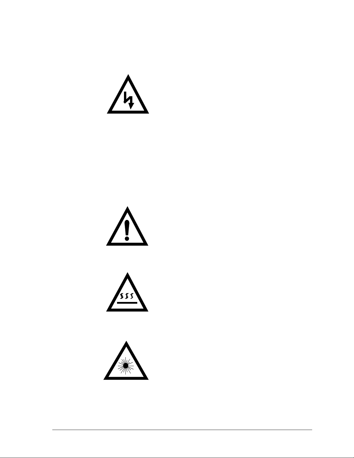
Hazard warning
Danger Electric
Shock Risk
When you see this safety sign on a system, it gives a warning of a hazard or
possibility of a hazard existing. The type of warning is given by the pictorial
representation on the sign plus text if used.
The safety color is black on a yellow background with a black symbol. To
ignore such a caution could lead to severe injury or death arising from an
unsafe practice. If voltage levels are included in the text they must indicate
the maximum level of the hazard in normal or fault condition.
Safety Precautions
Danger, Warning, or Caution warning
Symbol plus DANGER, WARNING or CAUTION:
These notices provide information intended to prevent
potential personal injury and equipment damage.
Hot Surface warning
Symbol plus HOT SURFACE:
These notices provide information intended to prevent
potential personal injury.
LED Radiation warning
Symbol plus LED RADIATION. DO NOT STARE
INTO BEAM. CLASS 2 LED PRODUCT:
These notices provide information intended to prevent
potential personal injury.
GIDDINGS & LEWIS MMC for PC Hardware Manual 3

1.4 Safety First
Giddings & Lewis equipment is designed and manufactured with
consideration and care to generally accepted safety standards. However, the
proper and safe performance of the equipment depends upon the use of sound
and prudent operating, maintenance and servicing procedures by trained
personnel under adequate supervision.
For your protection, and the protection of others, learn and always follow
these safety rules. Observe warnings on machines and act accordingly. Form
safe working habits by reading the rules and abiding by them. Keep these
safety rules handy and review them from time to time to refresh your
understanding of them.
1.5 Safety Inspection
1.5.1 Before Starting Operations
1. Ensure that all guards and safety devices are installed and
operative and all doors which carry warning labels are closed
and locked.
Safety Precautions
2. Ensure that all personnel are clear of those areas indicated as
potentially hazardous.
3. Remove (from the operating zone) any materials, tools or
other objects that could cause injury to personnel or damage
the system.
4. Make sure that the control system is in an operational condition.
5. Make certain that all indicating lights, horns, pressure gauges
or other safety devices or indicators are in working order.
1.6 After Shutdown
Make certain all controlled equipment in the plant is safe and the associated
electrical, pneumatic or hydraulic power is turned off. It is permissible for
the control equipment contained in enclosures to remain energized provided
this does not conflict with the safety instructions found in this section.
1.7 Operating Safely
1. Do not operate the control system until you read and understand the
operating instructions and become thoroughly familiar with the system
and the controls.
2. Never operate the control system while a safety device or guard is
removed or disconnected
4 MMC for PC Hardware Manual GIDDINGS & LEWIS

Safety Precautions
3. Where access to the control system is permitted for manual operation,
only those doors which provide that access should be unlocked. They
should be locked immediately after the particular operation is completed.
4. Never remove warnings that are displayed on the equipment. Torn or
worn labels should be replaced.
5. Do not start the control system until all personnel in the area have been
warned.
6. Never sit or stand on anything that might cause you to fall onto the control equipment or its peripheral equipment.
7. Horseplay around the control system and its associated equipment is
dangerous and should be prohibited.
8. Know the emergency stop procedure for the system.
9. For maximum protection when carrying out major servicing requiring
the system to be powered down, the power source should be locked
using a lock for which only you have the key. This prevents anyone
from accidentally turning on the power while you are servicing the
equipment.
10. Never operate the equipment outside specification limits.
11. Keep alert and observe indicator lights, system messages and warnings
that are displayed on the system.
12. Do not operate faulty or damaged equipment. Make certain proper service and maintenance procedures have been performed.
1.8 Electrical Service & Maintenance Safety
1.
ALL ELECTRICAL OR ELECTRONIC MAINTENANCE AND
SERVICE SHOULD BE PERFORMED BY TRAINED AND
AUTHORIZED PERSONNEL ONLY.
2. It should be assumed at all times that the POWER is ON and all conditions treated as live. This practice assures a cautious approach which
may prevent accident or injury.
3. To remove power:
LOCK THE MAIN SWITCH IN THE OPEN POSITION.
USE A LOCK TO WHICH ONLY YOU HAVE THE KEY.
4. Make sure the circuit is safe by using the proper test equipment. Check
test equipment regularly
5. Capacitors take time to discharge. Care should be taken in manual discharging of capacitors
GIDDINGS & LEWIS MMC for PC Hardware Manual 5

Safety Precautions
6. There may be circumstances where troubleshooting on live equipment
is required. Under such conditions, special precautions must be taken:
Make sure your tools and body are clear of the areas of equipment
•
which may be live.
Extra safety measures should be taken in damp areas.
•
Be alert and avoid any outside distractions.
•
Make certain another qualified person is in attendance.
•
7. Before applying power to any equipment, make certain that all personnel are clear of associated equipment.
8. Control panel doors should be unlocked only when checking out electrical equipment or wiring. On completion, close and lock panel
doors.
9. All covers on junction panels should be fastened closed before leaving any job.
10. Never operate any controls while others are performing maintenance
on the system.
11. Do not bypass a safety device.
12. Always use the proper tool for the job.
13. Replace the main supply fuses only when electrical power is OFF
(locked out).
1.9 Safe Cleaning Practices
1. Do not use toxic or flammable solvents to clean control system
hardware.
2. Turn off electrical power (lock out) before cleaning control system
assemblies.
3. Keep electrical panel covers closed and power off when cleaning an
enclosure.
4. Always clean up spills around the equipment immediately after they
occur.
5. Never attempt to clean a control system while it is operating.
6. Never use water to clean control equipment unless you are certain that
the equipment has been certified as sealed against water ingress. Water
is a very good conductor of electricity and the single largest cause of
death by electrocution.
6 MMC for PC Hardware Manual GIDDINGS & LEWIS

2 Introduction
This document contains information for the MMC for PC Control System.
Block I/O information can be found in the PiC900 Hardware Manual. Software
information can be found in the PiCPro Software Manual, the Function/Function
Block Reference Guide, ASFB Manuals or on-line.
The MMC for PC board offers a complete solution to both machine and motion control
directly from a PC. The board conforms to the PCI Bus Standard.
The major components of the MMC for PC motion control system are a PCI board,
(analog servo or SERCOS), the MMC for PC Analog Servo Interface Unit (ASIU) and
related connecting hardware. An optional mezzanine type Fieldbus Module is also
available to facilitate network connections.
For SERCOS motion control, connections are made from the MMC for PC SERCOS
board to SERCOS drives using a pair of fiber optic SMA connectors (one for
transmitting signals and one for receiving signals.).
Introduction
For analog motion control, an ASIU is connected directly to the MMC for PC Analog
Servo board using a standard category 5 cable with RJ45 connectors. The MMC for
PC Analog Servo board can also communicate with up to eight ASIUs by connecting
one ASIU to the MMC for PC Analog Servo board and connecting additional ASIUs.
The MMC for PC is controlled by PiC Pro for Windows software that runs under the
Windows NT or Windows 2000 Operating System. Ladder logic programming is used
for machine control.
The MMC for PC is able to operate when the host PC is shut off. This is accomplished
through a connection with an optional external +24VDC power supply.
GIDDINGS & LEWIS MMC for PC Hardware Manual 7
2.1 Computer Workstation Requirements
2.1.1 Recommendations for MMC for PC Controller
Table 1: Recommendations for MMC for PC Controller
Introduction
Computer
Memory
Monitor
Disk drives
Power saver option in BIOS should not be set when using an MMC
for PC. If the power saver option in BIOS is set, the NT server will
also shut down and cause a communications error.
A 133 MHz or faster Pentium processor and a free PCI
slot running Windows NT4.0 or Windows 2000. If a network card is installed, it must be a PCI network card (an
ISA network card is not recommended).
64 MB of RAM, minimum; 128 MB of RAM, recommended
VGA or higher resolution display adapter
Typically, 60 MB of hard disk space required
IMPORTANT
8 MMC for PC Hardware Manual GIDDINGS & LEWIS
2.2 Major Components
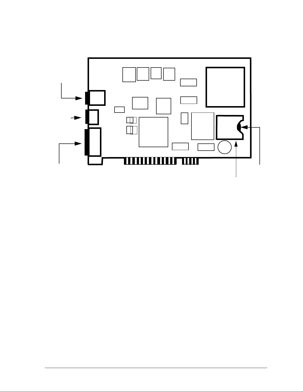
2.2.1 SERCOS Board
The major components of the SERCOS board are illustrated in
Figure 1 and include the following:
A standard half size 32 bit 5 volt 33Mhz PCI card
•
A 32-bit RISC processor running at 128 Mhz (includes
•
numeric coprocessor)
One SERCOS port that includes a fiber optic input connec-
•
tion and an output connection for one SERCOS ring.
+24V Power connector
•
A 9-Pin Block I/O interface port
•
A lithium coin cell backup battery
•
Introduction
Figure 1: Component View of MMC for PC SERCOS Control Board
SERCOS
Receive
Port
SERCOS
Transmit
Port
+24V Power
Connector
and Lockout
Switch Input
Block I/O
Interface Port
(to Block I/O)
PCI Card
PCI Connector
32-bit RISC
Processor
+
Battery
Battery
Holder
GIDDINGS & LEWIS MMC for PC Hardware Manual 9
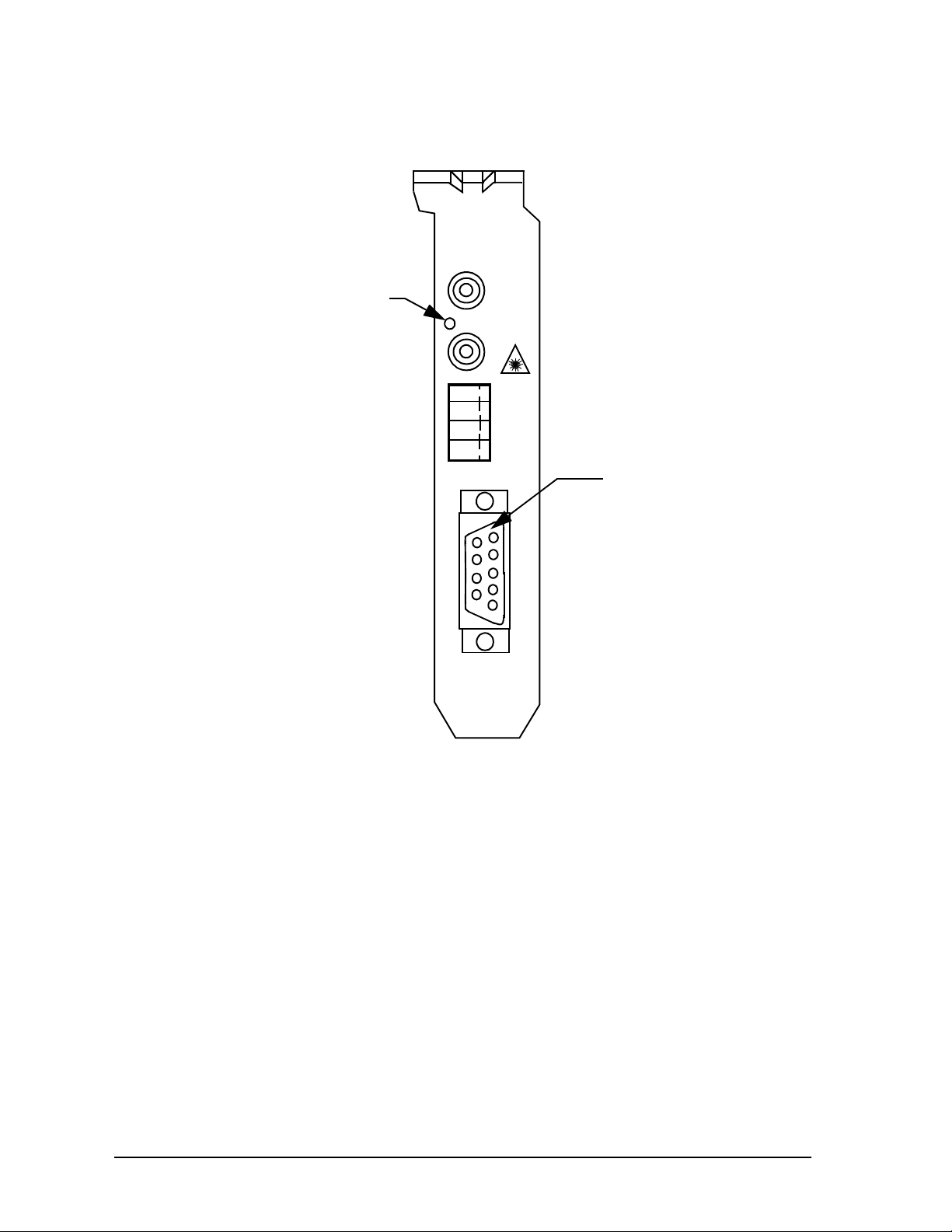
Figure 2: End Bracket Faceplate for SERCOS Board
RX
Diagnostic
LED
DIAG
TX
-R
+R
-V
+V
9 Pin D-sub
Connector
Introduction
BLOCK
I/O
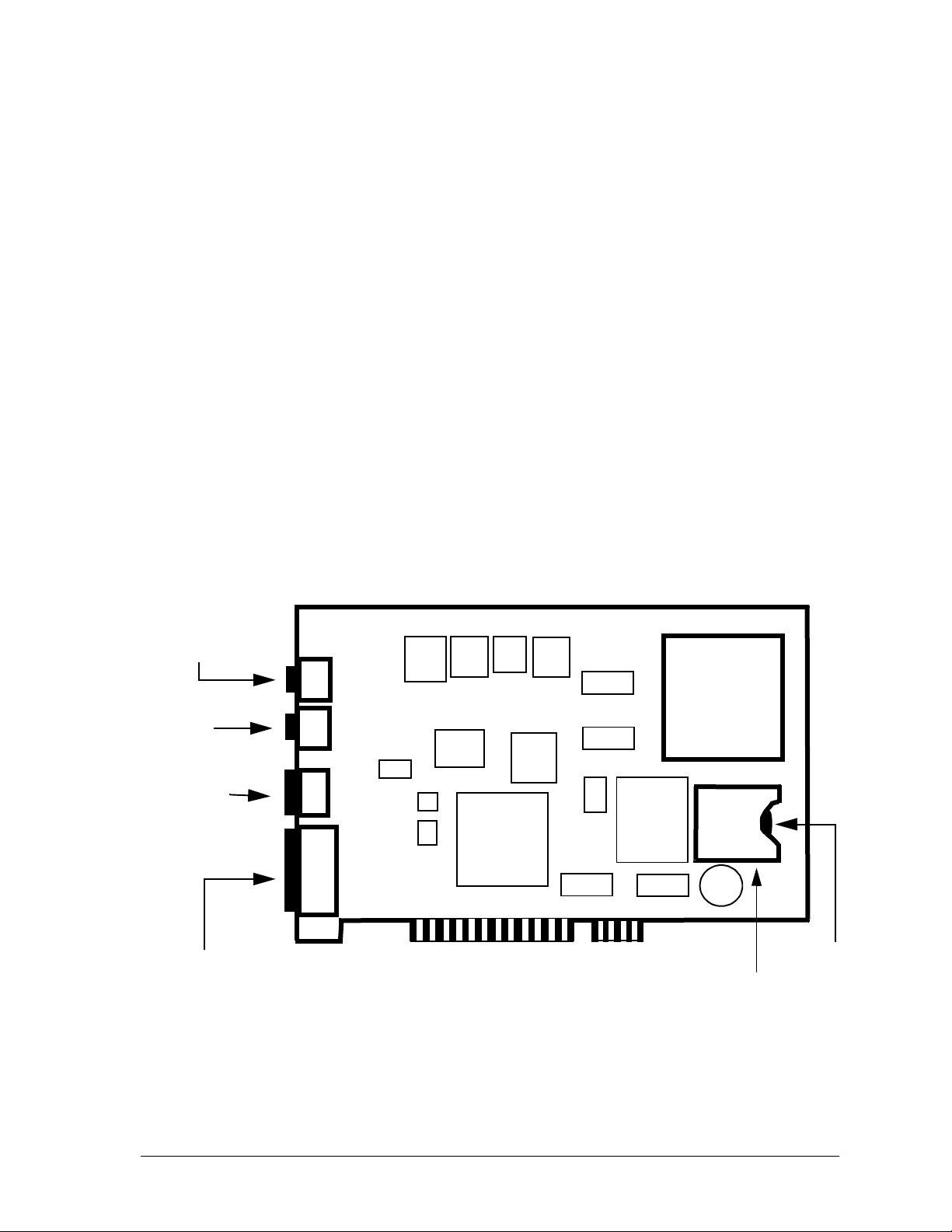
2.2.2 Analog Servo Board
The major components of the Analog Servo board are illustrated in
Figure 3 and include the following:
A standard half size 32 bit 5 volt 33Mhz PCI card
•
An 32-bit RISC processor running at 128 Mhz (includes
•
numeric coprocessor)
A RJ45 connector for communication with ASIUs
•
A 9-Pin Block I/O interface port
•
A lithium coin cell backup battery
•
10 MMC for PC Hardware Manual GIDDINGS & LEWIS
Introduction
Figure 3: Component View of MMC for PC Analog Servo Board
RJ45 Connector
(to ASIU)
+24V Power
Connector
and Lockout
Switch Input
Block I/O
Interface Port
PCI Card
PCI Connector
32-bit RISC
Processor
+
Battery
Battery
Holder
GIDDINGS & LEWIS MMC for PC Hardware Manual 11
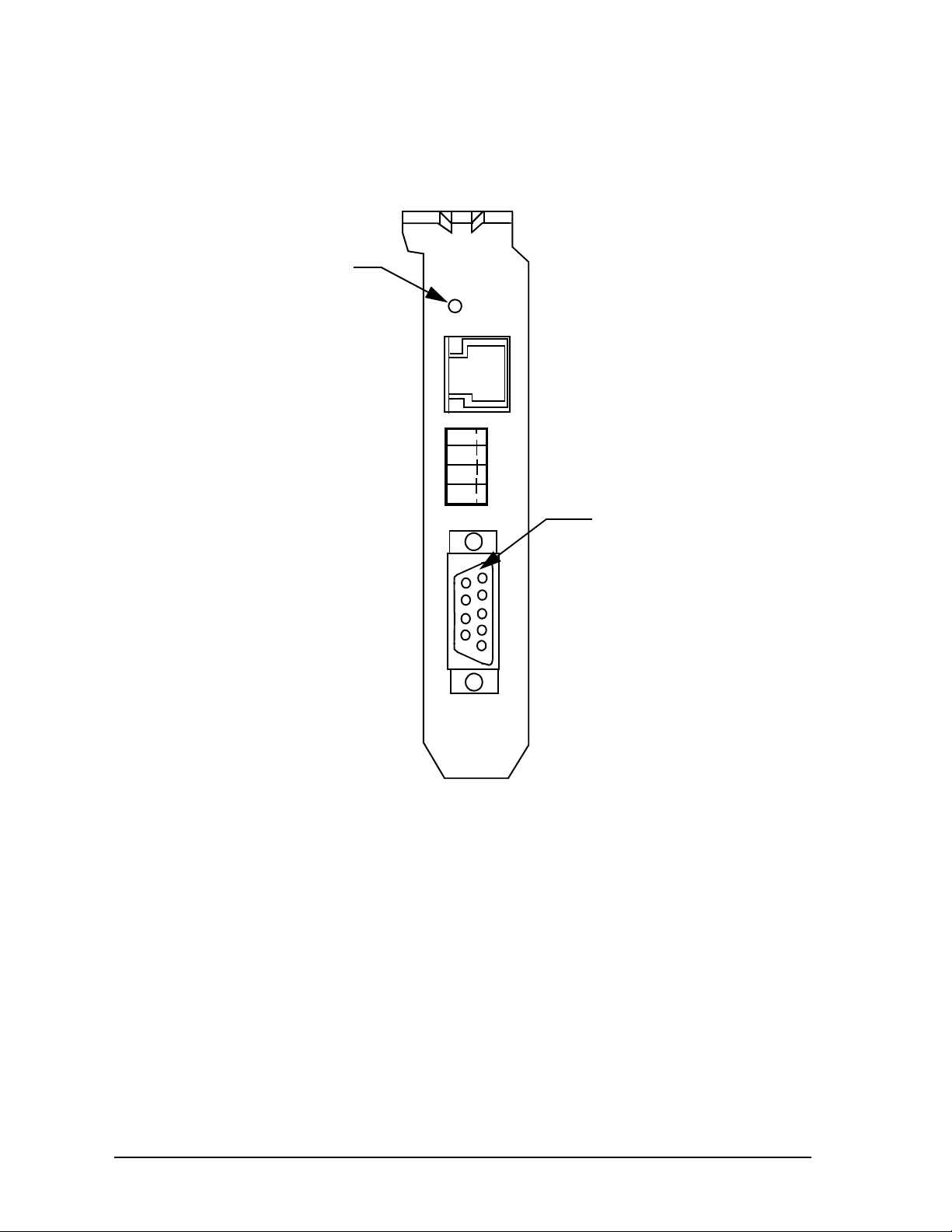
Figure 4: End Bracket Faceplate for Analog Board
Diagnostic
LED
DIAG
TO
ASIU
-R
+R
-V
+V
Introduction
BLOCK
I/O
9 Pin D-sub
Connector
12 MMC for PC Hardware Manual GIDDINGS & LEWIS
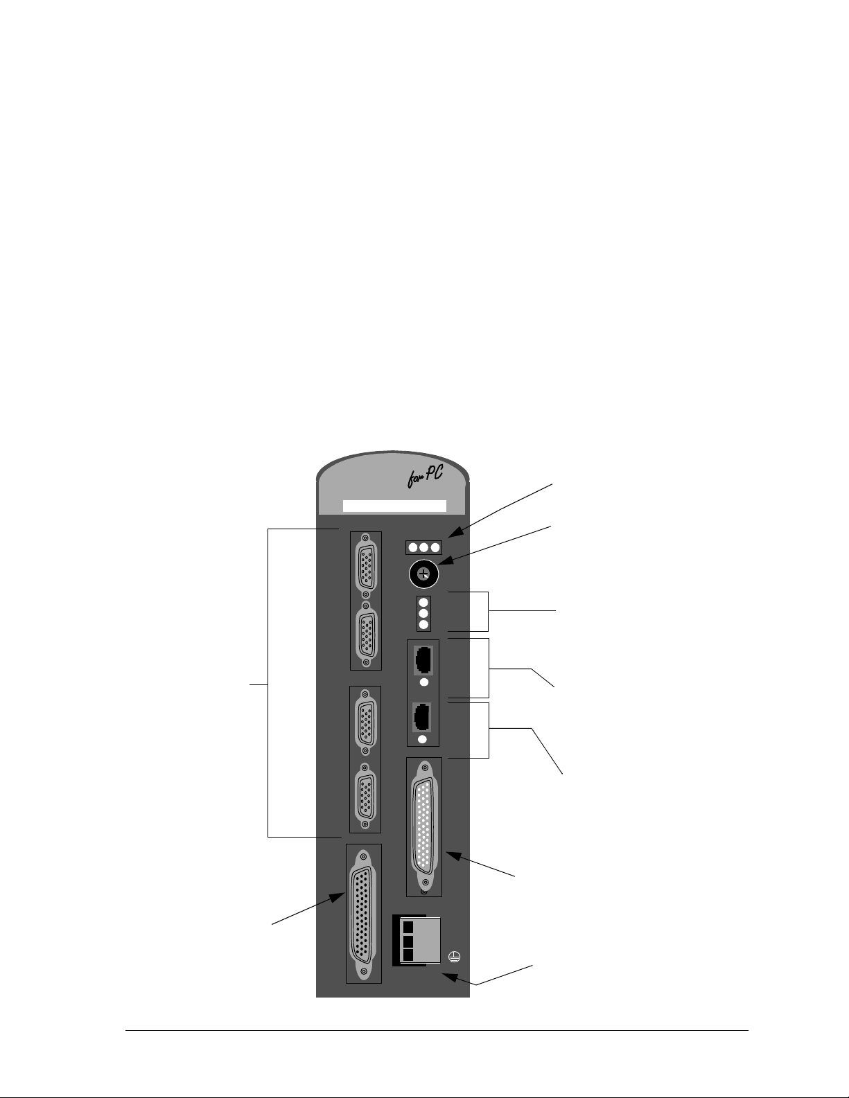
2.2.3 Analog Servo Interface Unit (ASIU)
The Analog Servo Interface Unit (ASIU) provides servo axis
interface signals and general purpose I/O for the MMC for PC
Analog Board. The ASIU is available in two models:
ASIU-A2 (2 1/2 servo axis unit)
•
ASIU-A4 (4 1/2 servo axis unit)
•
Communication between the ASIU and the MMC for PC Analog
Board (mounted in a Personal Computer) is accomplished through
the use of a 10Base-T Ethernet interface. The MMC for PC Analog
Board can communicate with up to eight ASIUs by connecting the
ASIUs together.
Figure 5: Analog Servo Interface Unit (ASIU)
Scanning (S) LED
Power (P) LED
Diagnostic (D) LED
M
Analog Servo Interface Unit
GIDDINGS & LEWIS
M
C
C
CC
PSD
®
Address Rotary Switch
Introduction
Axis
Ports
(A3 and A4
are not on the
ASIU-A2)
Auxiliary I/O
Port
A4
A3
A2
A1
AUX
I/O
9
8
7
PWR
0
1
2
3
ADR
4
6
SEL
5
COL
TXD
RXD
IN
IN
OK
OUT
OUT
OK
Collision (COL) LED
Transmit (TXD) LED
Receive (RXD) LED
RJ45 Connector
Port (from MMC for PC),
Link IN OK LED
RJ45 Connector
Port (to additional ASIUs),
GEN
I/O
Link OUT OK LED
General I/O Port
+24V
COM
Power
Connector
GIDDINGS & LEWIS MMC for PC Hardware Manual 13

2.2.3.1 ASIU Components
Major external components of the ASIU include:
Two RJ45 connectors and associated communica-
•
tions circuitry to communicate with the MMC for
PC Analog Board and other ASIUs.
A screwdriver-actuated rotary switch (0 through 9)
•
that allows the user to define the ASIU address.
Addresses 1 through 8 define valid ASIUs, and
addresses 0 and 9 effectively remove the ASIU from
the system (the two RJ45 connectors are still active,
but the ASIU will not be seen by the MMC for PC
Analog Board).
A 3-pin power connector to supply 24VDC to the
•
ASIU
A General I/O port connector for connecting 16
•
inputs and 16 outputs to user devices.
Introduction
An Auxiliary I/O Port for connecting one quadrature
•
incremental encoder, five fast DC inputs, one analog
input channel and twelve DC inputs to user devices.
Four Axis connectors are available on the ASIU-A4
•
and two are available on the ASIU-A2. Axis connections include one analog output, one encoder
input, two DC outputs and one DC input to user
devices.
LED indicators include the following:
Scanning (Green) – Indicates CPU is communicat-
•
ing with the ASIU.
Power (Green) – Indicates +5V is OK.
•
Diagnostic (Yellow) – On briefly during startup. If it
•
remains ON, ASIU has failed startup diagnostics.
Link OK (Green) – Located near each of two RJ45
•
connectors. These LEDs indicate that the attached
RJ45 cable is wired correctly and both ends are
powered up.
Collision (Red) – Located in the cut-out area of the
•
plastic faceplate. Indicates that 2 or more ASIUs are
at the same address.
Transmit (Green) – Located in the cut-out area of the
•
plastic faceplate. Indicates that this ASIU is sending
a packet of information.
14 MMC for PC Hardware Manual GIDDINGS & LEWIS
Receive (Green) – Located in the cut-out area of the
•
plastic faceplate. Indicates that this ASIU is receiving a packet of information.
2.2.3.2 ASIU Axis I/O
The ASIU provides conventional analog/digital
interfacing for two or four drives.
Typical signals needed to interface to an analog drive
are provided by the ASIU. The drive command is in the
form of an analog voltage (±10V). Feedback is accepted
from quadrature type encoders with RS422 style
differential outputs. Digital I/O (+24 VDC) is used for
drive enable, reset, and fault signals.
The ASIU is offered in both 2 1/2 (ASIU-A2) and 4 1/2
(ASIU-A4) axis configurations. An axis is considered to
be an analog output with a corresponding encoder input.
In each configuration shown below, note that there is an
extra encoder input. This is referred to as a half axis.
Introduction
Table 2: Available Axis I/O for ASIU
Available I/O ASIU-A2 ASIU-A4
Analog Inputs 1 1
Analog Outputs 2 4
Encoder Inputs 3 5
Axis DC Inputs 2 4
Axis DC Outputs 4 8
Axis Fast DC Inputs 3 5
GIDDINGS & LEWIS MMC for PC Hardware Manual 15

NOTES
Introduction
16 MMC for PC Hardware Manual GIDDINGS & LEWIS
Installation of the MMC for PC Board and Software
Suite
3 Installation of the MMC for PC Board and
Software Suite
3.1 Installing the MMC for PC Board
1. Shut down and turn off your computer, monitor and all attached
peripherals.
2. Unplug each component from the wall electrical outlet or surge protector/power strip.
3. Disconnect all power to the computer and MMC for PC control system.
WARNING
Before you install an MMC for PC board in the
computer, make sure that power is disconnected
from the computer and to the devices the MMC for
PC is wired to. Make sure the computer is adequately grounded before installing an MMC for PC
board. Any attempt to operate or service the computer without adequate ground may result in serious
personal injury and/or damage to the MMC for PC
board and control system.
4. Remove the computer cover as described in the documentation for your
specific computer.
5. Locate an empty 32-bit PCI bus expansion slot in which to install the
MMC for PC board.
6. At the back of the computer, the empty expansion slot should have a
metal cover that is secured to the computer frame. Remove the screw
that secures the expansion slot cover and remove the cover.
GIDDINGS & LEWIS MMC for PC Hardware Manual 17

Installation of the MMC for PC Board and Software Suite
STATIC ELECTRICITY PRECAUTIONS
The MMC for PC board and internal components of the PC are sensitive to static electricity. The following precautions reduce the possibility of damaging the PC or MMC for PC board components:
Before handling the MMC for PC board or touching anything inside the PC, discharge your body’s static electric charge by touching a grounded (earthed) surface. If the PC is connected to a
grounded outlet, you can do this by touching the outside metal
piece of the PC chassis.
Do not remove the MMC for PC from its antistatic bag until you are
ready to install it.
When removing the board from the anti-static bag, hold it by the
edges and the metal support mounting bracket. Avoid touching
components on the board and the PCI Connectors.
Do not slide the board over any surface.
Avoid plastic, vinyl and styrofoam in your work area.
If you remove the MMC for PC board from the PC slot, immediate-
ly place it in an antistatic bag.
7. Remove the MMC for PC board from its anti-static bag.
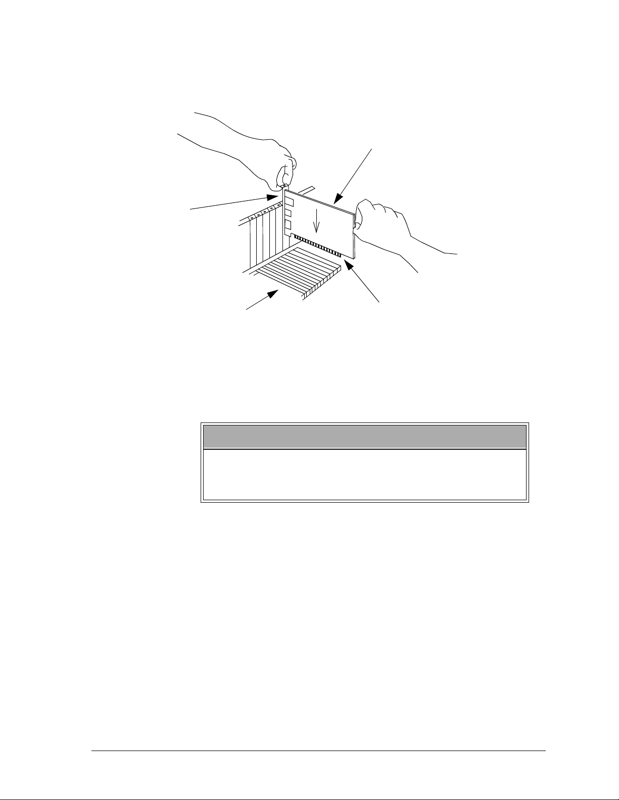
8. Refer to Figure 6. Position the MMC for PC board over the empty
expansion slot so the external connectors face the back of the computer
and PCI Connector edge of the board is over the slot. Insert the board
with the bottom edge level to the slot.
angle.
Carefully push the board straight down until the board is fully
Never insert the board at an
seated in the slot. Visually inspect the connection.
18 MMC for PC Hardware Manual GIDDINGS & LEWIS
External
Connectors
Installation of the MMC for PC Board and Software
Suite
Figure 6: Installing the MMC for PC Board
MMC for PC Board
Slots
PCI Connector
9. Attach the MMC for PC chassis to the back of the computer frame by
reinserting and securing the screw from the expansion slot cover.
IMPORTANT
It is very important that the board is firmly attached to the
computer frame. Failure to do so may cause poor connections to external devices or damage to the board.
10. Reattach and secure the screws for the computer cover.
11. Plug in all power cords and turn on the monitor. Turn on the computer.
If you do not get the proper start-up display, check all connections and
make the necessary changesnotes
GIDDINGS & LEWIS MMC for PC Hardware Manual 19

Installation of the MMC for PC Board and Software Suite
3.2 Installing the Software Suite
The MMC for PC Software Suite CD contains 3 different software packages:
PiCPro for Windows Monitor Edition, Giddings & Lewis OPC Server and
MMC for PC Support Software. At a minimum you must install the MMC
for PC Support Software.
Instructions for installing the Support Software are provided in the following
section titled "Installing the Support Software". It is recommended that you
install this package first. The other three software packages are optional.
They only have to be installed if there is a need to use them. The software
packages can be installed in any order. To install any of these packages do
the following:
1. Log in as a user with administrative privileges.
2. Insert the CD-ROM. Setup should launch automatically. If this does not
happen, click the Start button on the Task bar, select Settings, select
Control Panel, open Add/Remove Programs Icon and click Install.
3. Follow the instructions on the screen and select the appropriate item to
install.
3.3 Installing the Support Software
This section describes procedures to install and uninstall the Support
Software required to support the MMC for PC hardware on Windows 2000
and WindowsNT. These programs include the driver, NT Socket Server,
and a status program, which allow you to view the basic functions and
settings of the hardware.
NOTE
If you have difficulty installing the Support Software, enter BIOS setup and turn off all interrupts for the PCI slot that the MMC for PC is
plugged into. Also, in BIOS, there may be a setting to indicate that the
PC operating system is Plug and Play compatible. Set this to
Windows 2000 or to NO for WindowsNT.
1. Make sure the MMC for PC board is installed in the PC.
2. Log in as a user with administrator privileges.
YES
for
20 MMC for PC Hardware Manual GIDDINGS & LEWIS
Installation of the MMC for PC Board and Software
Suite
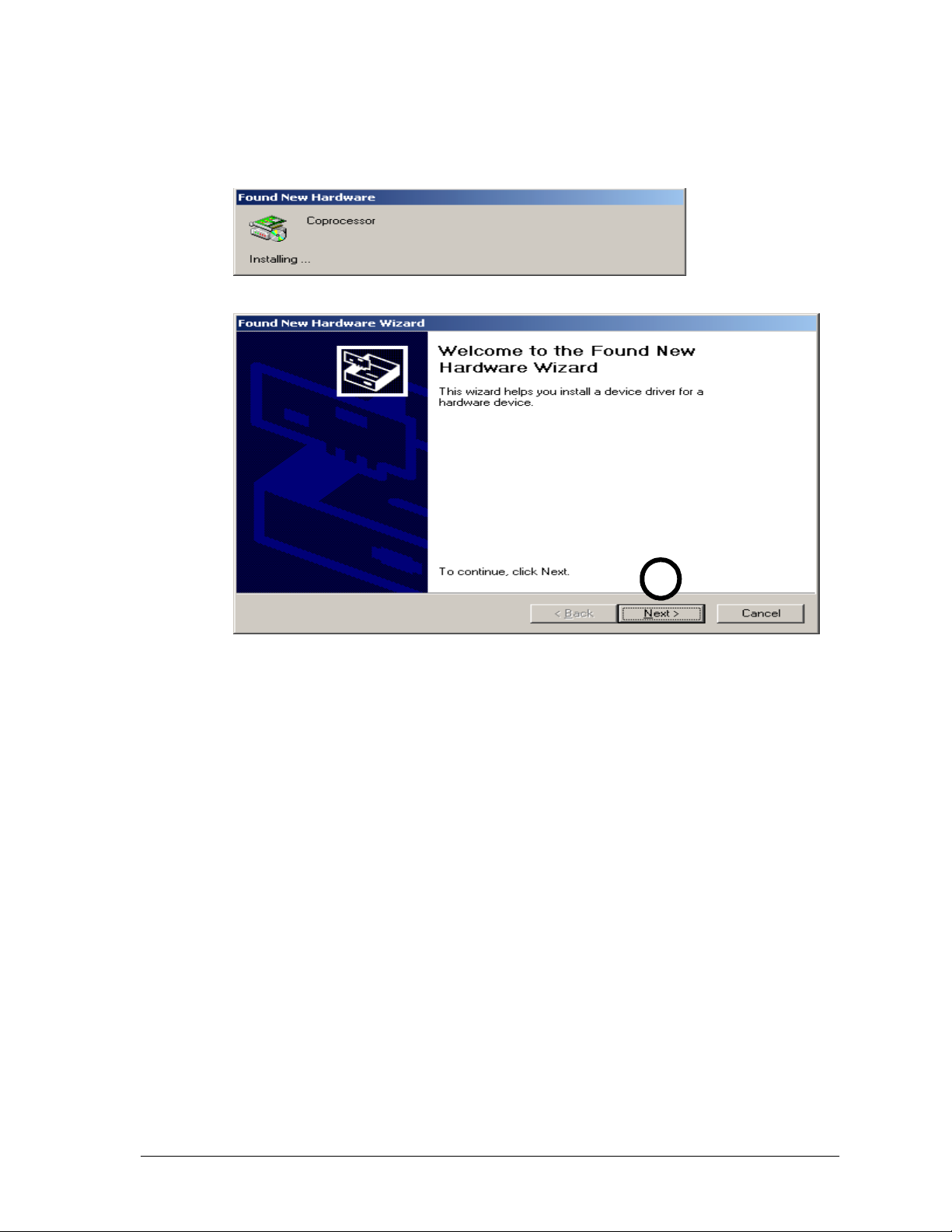
3. Power on the PC. If you are using Windows 2000, a "Found
New Hardware" wizard will appear. Click on the
Cancel
but-
ton.
3
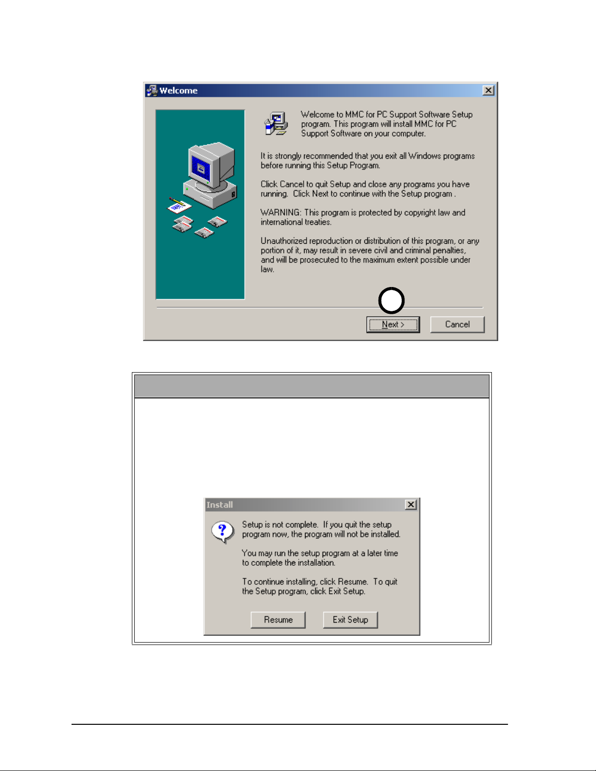
4. Insert the CD-ROM. Setup should launch automatically. If this does not
happen, click the
Control Panel, open the Add/Remove Programs Icon and click
From the list of selections, double click on
port Software
and the "Welcome" window will be displayed.
button on the Task bar, select Settings, select
Start
Install MMC for PC Sup-
Install
.
GIDDINGS & LEWIS MMC for PC Hardware Manual 21
Installation of the MMC for PC Board and Software Suite
4
NOTE
If you do not want to continue with the installation of the MMC for
PC Support software, click on the Cancel button. The following window will be displayed. Click on the
Resume
continue installing the software. Click on the
button if you want to
Exit Setup
button if you
want to exit the software installation procedure. This option is available in all of the Support Software installation windows.
22 MMC for PC Hardware Manual GIDDINGS & LEWIS
Installation of the MMC for PC Board and Software
Suite
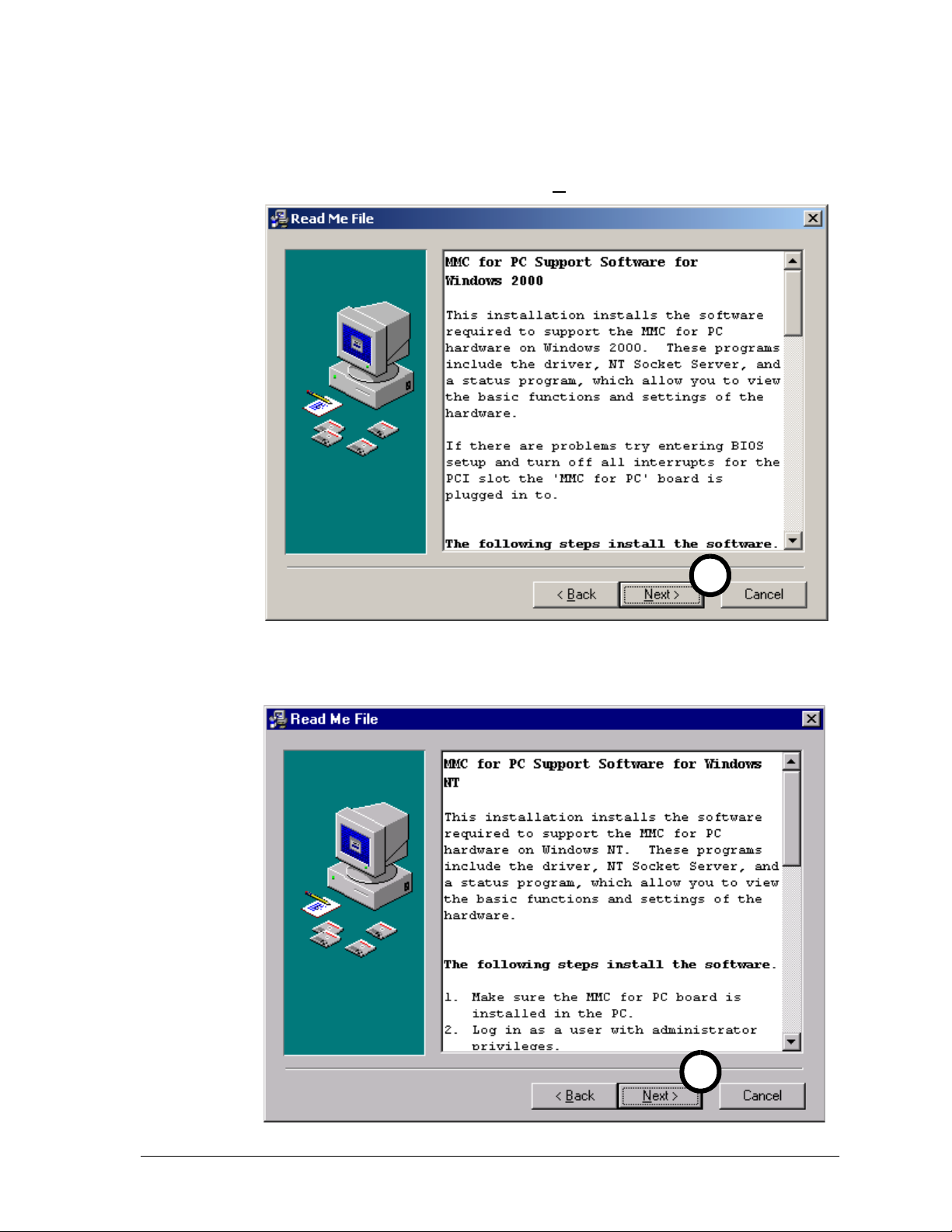
5. The "Read Me File" window will be displayed. This window
includes a description of the installation procedure, an unistall
procedure and basic information on troubleshooting and support links. Click on the
button to continue.
Next
OR
5
5
GIDDINGS & LEWIS MMC for PC Hardware Manual 23
Installation of the MMC for PC Board and Software Suite
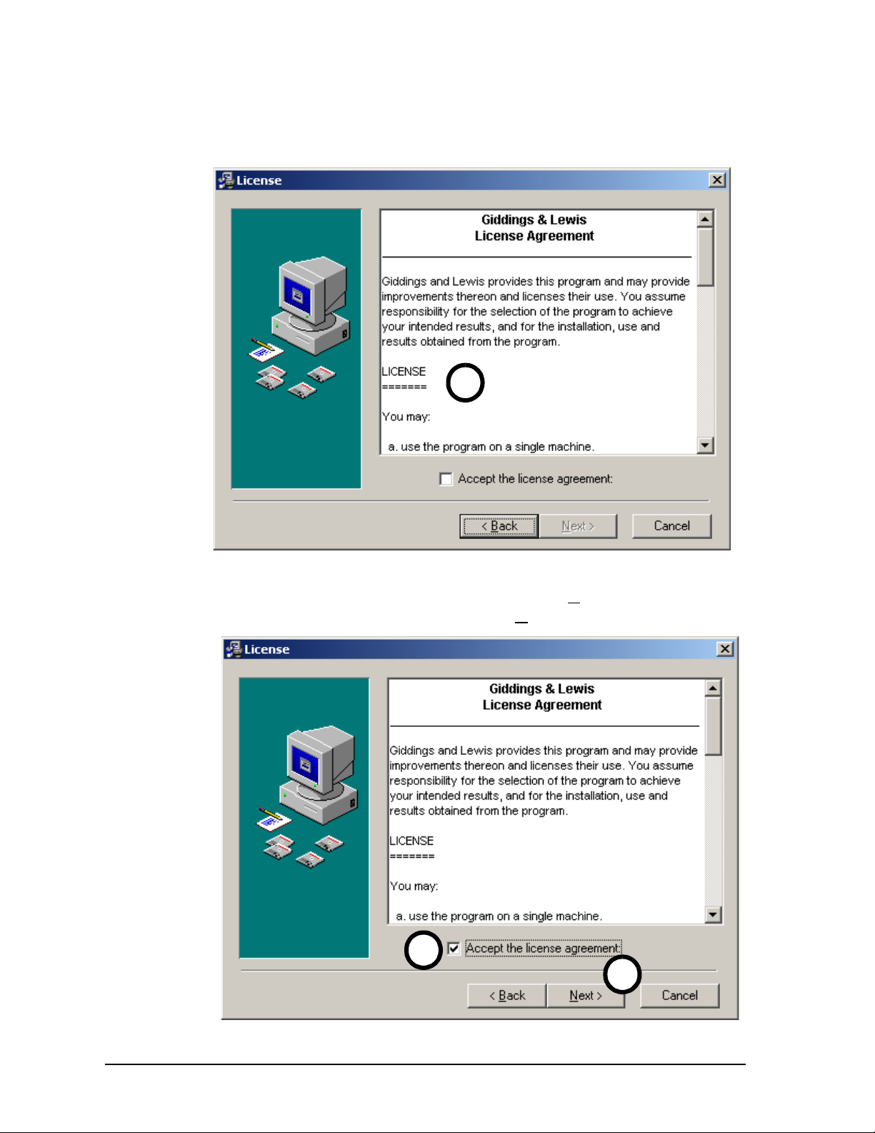
6. The "License" window will be displayed. This window displays a description of the Giddings & Lewis license agreement. Read and understand the license agreement.
6
7. Click in the
Accept the license agreement
box. A check
mark will appear in the box and the Next button will be available to choose. Click on the
Next
button.
7
7
24 MMC for PC Hardware Manual GIDDINGS & LEWIS
 Loading...