

Gicam WIN6 User Manual

Manuale
Handbuch
Manual

Manuale d’istallazione e d’uso
Installation and user man ual
Installations- und Bedienungs anlei tung
LIMITATORE di carico
load LIMITER
LASTBEGRENZER

Sommario / Table of contents / Inhaltsverzeichnis
Sommario / Table of contents / Inhaltsverzeichnis .................................................................... 1
Installation manual ....................................................................................................................... 3
Technical specification ................................................................................................................................... 3
Symbology ..................................................................................................................................................... 4
Warnings ........................................................................................................................................................ 4
Identification plate of the instrument .............................................................................................................. 4
Power supply of the instrument ...................................................................................................................... 5
Connection of the load cells ........................................................................................................................... 5
Connection logical input ................................................................................................................................. 6
Relay output connection................................................................................................................................. 6
Serial RS485 connection................................................................................................................................ 6
Serial RS232 connection................................................................................................................................ 7
Connection of analog output (optional) .......................................................................................................... 7
Characteristics ............................................................................................................................................ 7
Connection summary ..................................................................................................................................... 8
Termination resistance RS485 and RS422.................................................................................................... 8
User manual ................................................................................................................................ 11
Main characteristics of use .......................................................................................................................... 11
Display signals ............................................................................................................................................. 11
Signal weight not detectable ................................................................................................................ 11
Signal of underweight ........................................................................................................................... 11
Overload signal ..................................................................................................................................... 11
LED indicators (red) ..................................................................................................................................... 11
Other LED indicators (green) ....................................................................................................................... 11
Use of the keyboard ..................................................................................................................................... 12
Data setting .............................................................................................................................................. 12
Restore zero (semi-automatic zero) ......................................................................................................... 12
Self weighing tare (autotare) .................................................................................................................... 12
Input and output ........................................................................................................................................ 13
Input ...................................................................................................................................................... 13
Output ................................................................................................................................................... 13
Commissioning the instrument ................................................................................................................. 13
Calibration data menu .................................................................................................................................. 14
Weighing system capacity .................................................................................................................... 14
Sensibility .............................................................................................................................................. 14
Divisions value ...................................................................................................................................... 14
Weight calibration and linearization ............................................................................................................. 15
Zero calibration ..................................................................................................................................... 15
Full scale calibration ............................................................................................................................. 15
Weighing parameters setting menu ............................................................................................................. 16
Weight filter ........................................................................................................................................... 16
Weight stability ...................................................................................................................................... 16
Weighing parameters setting menu ............................................................................................................. 17
Autozero at power up ............................................................................................................................ 17
Tracking of zero .................................................................................................................................... 17
Serial menu .................................................................................................................................................. 17
Select baud rate .................................................................................................................................... 17
Select data format ................................................................................................................................. 17
Analog output set-up and test menu (optional) ............................................................................................ 18
Full scale analog output ........................................................................................................................ 19
Pagina – page – Seite 1

Analog output operation mode .............................................................................................................. 19
Test analogue output ............................................................................................................................ 19
Range analogue output ........................................................................................................................ 19
Offset adjustment (calibration) .............................................................................................................. 19
Limit values ............................................................................................................................................... 19
Output configuration ..................................................................................................................................... 20
Set point programming ......................................................................................................................... 20
Excitation delay ..................................................................................................................................... 20
Programming polarity of intervention of the logic output 3 ................................................................... 20
Serial protocol .............................................................................................................................................. 21
Continuous transmission protocol ............................................................................................................ 21
Troubleshooting Guide ................................................................................................................................. 22
Pagina – page – Seite 2

Installation manual
Technical specification
Board power supply 12 – 24 V ac ± 15 %
Power consumption 4 W
Insulation Class III
Storage temperature - 20 °C / + 60 °C (-4 °F / 140 °F)
Operating temperature - 10 °C / + 50 °C (14 °F / 122 °F)
Humidity Max. 85% non-condensing
Weight d isplay Numeric 6-digit, 7-segment LED (h 14mm)
LED 5 3 mm indicator LEDs of which 3 indicate the relay outputs status
Keyboard 4 mechanical keys
Overall dimensions 115 x 93 x 65 mm (4.53 x 3.66 x 2.56 in)
Installation Support DIN or OMEGA rail
Support material Polyamide 6.6 UL 94V-0, sel f-extinguishing
Wire connections Removable screw terminals
Pitch screws terminal blocks 5,08 mm
Input sensivity load cella (max. 4) ≥ 0,02 µV
Linearity < 0,01 % of full scale
Temperature deviation <0,001 % of full scale/ °C
Internal resolution 24 bit
Measuring range From -3.9 mV/V to +3.9 mV/V
Output rate 10 Hz
Digital filter 0.1 Hz – 10 Hz, selectable
Weight d ecimals From 0 to 3 decimals
Calibration Zero and full scale Executable through buttons
Logic alarm outputs 2 relay out (24 V DC/AC, one NO contact),
1 relay out (24 V DC/AC, one changeover contact), relay contact capacity 0.5 A
Logical inputs 1 optically isolated dry contact
Analogue output (option) tension 0 – 10 V / 0 – 5 V
Analogue output (option) c urrent 0 – 20 A / 4 – 20 m A
Impedance tension ≥ 10 kΩ
Impedance current ≤ 300 Ω
Resolution 16 bit
Calibration Digital through keyboard
Linearity < 0,03 % of full scale
Serial ports RS 232 / RS485 (alternatively)
Baud rate Up to 115 kb/s (default 9600 b/s)
Maximum cable length 15 m (RS323), 1000 m (RS485)
Program code memory 32 kbyte
Data memory 2 kbyte
Compliance to EMC norms EN61000-6-2, EN61000-6-3
Complia nce electric safety EN61010-1
Pagina – page – Seite 3

Symbology
!
i
!
Pay particular attention to the following indications!
Further information
Attention! This operation has to be carried out by specialized personnel.
Warnings
The procedures listed below have to be executed by specialized operators!
All connections have to be executed with the instrument shut off!
Identification plate of the instrument
It is important to communicate this data in case of request for information or indications concerning the instrum ent together with the pro gram num ber and the version wh ich are shown on the
cover of the manual and are displayed when the instrument is switched on.
Pagina – page – Seite 4

i
!
Power supply of the instrument
The instrument is powered via terminals 14 and 15.
The power cable must be routed separately from other power cables with different voltages,
load cell cables and logic inputs / outputs.
Supply voltage: 12 – 24 V ca ± 15%, 4 VA
Terminal board connection: 14 – Power supply +
15 – Zero
Connection of the load cells
The cell (or cells) cable(s) must not be cha nneled with other cables ( for example outputs
connected to contactors or power cables), but must follow its own path.
Any cable extension conn ec tions m ust be c areful ly shi elded, r espec ting t he co lor c ode and
using the cable of the type suppl ied by the m anufacturer. T he extension co nnections must
be made by welding, or through support terminal blocks or through the junction box supplied
separately.
The cell cable must have a number of conductors not higher than those used (4 or 6). In the
case of a multi-conductor cable, connect the remaining wires to the cell power supply (terminal 2)
Up to a maximum of 4 350 ohm cells in parallel can be connected to the instrument. The supply voltage of the
cells is 5 V direct current and is protected against a temporary short circuit. The measuring range of the instrument involves the use of load cells with sensitivity from 1 mV / V to 3 mV / V. The cable of the load cells must
be connected to ter minals 1 ... 6 of the r emovable terminal board. I n the case of a 4-conductor cell ca ble,
connect the cell power terminals to the respective polarity of the reference terminals (1-4 2-3).
Connect the shield of the cell cable to terminal 1!
Pagina – page – Seite 5
!
!
!
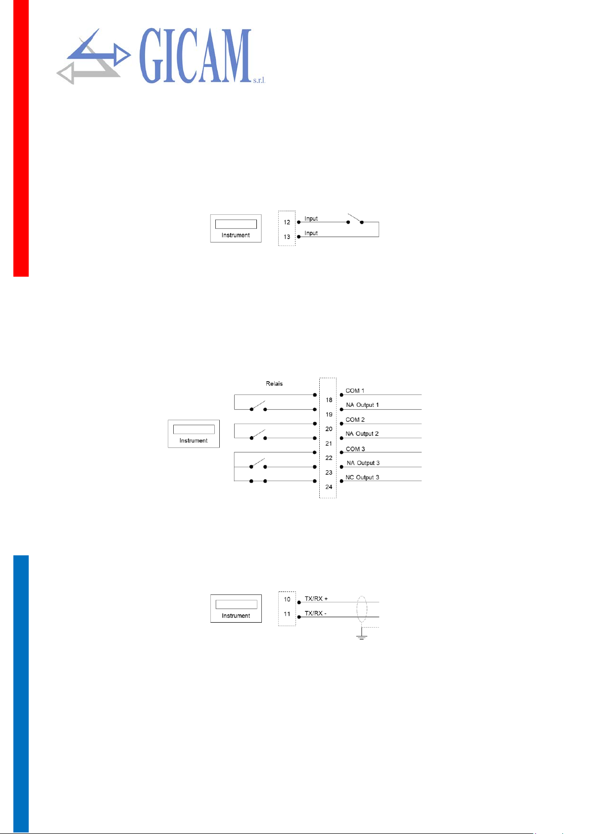
Connection logical input
The logic input is isolated from the instrument through an optocoupler.
The connection cable of the logic input must not be channeled with power or power cables
Use a connection cable as s hort as pos sible ( no longe r than 5 m eter s). If a longer length is
required, use a relay relay.
In the case of DC power supply (e.g. 24 V dc) and a long or disturbed input connection cable,
we recommend connecting pin 13 (input) and 14 (+ power supply) instead of 12 and 13
Relay output connection
The three outputs are relayed with three commons. The capacity of each contact is 24 V DC / VAC 0.5 A.
Serial RS485 connection
The cable must not be channe led with o ther ca bles (e .g. outputs connected to rem ote contr ol
switches or power supply cables), it must possibly follow its own path.
Pagina – page – Seite 6
!
!
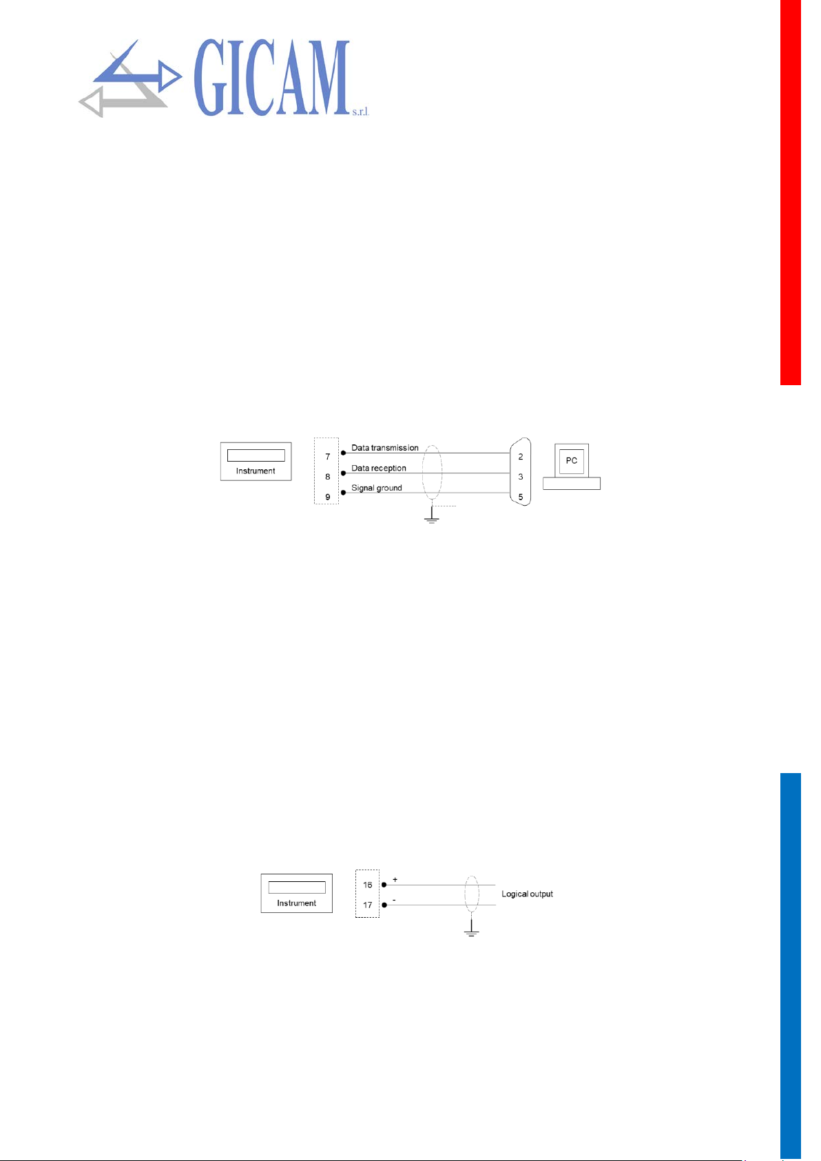
Serial RS232 connection
To m ake the seria l connection, us e a shielded cable, tak ing care to conn ect the screen t o
ground at only one of the two ends. If the cable has more conductors than those used, connect the free wires to the screen.
The serial connection cable must have a maximum length of 15 meters (EIA RS-232-C stand-
ards), beyond which it is ne cess ary to adopt t he RS4 22 int erf ace with which the i nstrum ent
is equipped.
The cable must not be channeled with other cables (e. g. outputs connected to remote control
switches or power cables), but it must possibly follow its own path.
The PC used for the connection must comply with the EN 60950 standard.
The connection diagram with a 9-pole PC connector is shown below:
Connection of analog output (optional)
The instrument, when it is in this hardware configuration, provides an analogue output in current or in voltage.
Characteristics
Analogue voltage output: range from 0 to 10 volts or from 0 to 5 Volts, minimum load 10 kΩ
Analogue current output: range from 0 to 20mA or from 4 to 20mA, maximum load 300Ω
The settings for the type of analog output supplied (voltage or current) are determined at the factory and must
be specified at the time of purchase.
To make the connect ion use a shi elded cabl e, taking c are to co nnect the sc reen t o ground
at only one of the two ends.
Analogue transm ission is particul arly sensitive to electrom agnetic disturbanc es; it is there-
fore suggested that the cables are as short as possible and that they follow their own path.
Pagina – page – Seite 7
 Loading...