

Gicam RQ Operational Handbook
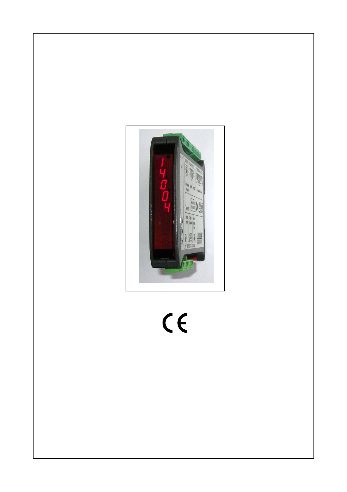
LOADING CELLS DIGITAL AMPLIFIER
RQ
OPERATIONAL HANDBOOK
SOFTWARE CODE: PTRQ01
VERSION: Rev.0.1

INDEX
PROPERTIES AND DISPLAY
MAIN USAGE PROPERTIES Pag. 2
MAIN DISPLAY Pag. 2
DISPLAY INDICATORS Pag. 2 - 3
DATA PROGRAMMING
KEYBOARD
FUNCTION KEY
OPERATING MODE Pag. 3
WEIGHT VIEW AND RESET AND ANALOG OUTPUT ADJUSTMENT Pag. 4
CONFIGURATION MENU Pag. 5 - 6 - 7
WEIGHT CALIBRATION Pag. 8
LOGIC OUTPUT Pag. 9
ANALOG OUTPUT Pag. 10
SERIAL PROTOCOL Pag. 11-12
PROBLEM SOLUTION Pag. 13
Pag. 3
Pag. 3
RQ device operational handbook
Pag. 1
MAIN USAGE PROPERTIES
Main operational characteristics are:
Weight value visualization from linked loading cells;
2 analog output administration: one in Volt and another in mA;
Value view of the Volt analog output;
2 logical output administration;
1 logical input administration;
RS232 connection capability for serial data transmission (ongoing or on request);
RS485 connection capability for serial data transmission (ongoing or on request);
Instead of RS485 serial port it is possible to connect a PROFIBUS module for serial data transmission.
MAIN DISPLAY
DISPLAY
On the 5-digit display the lower positioned digit stand for the less meaningful. Starting the device, the value
appearing is the analog output in Volts or the gross weight depending on the parameter “VISUA” setup (see
pag.5). It is also possible to change the view (weight/analog output or viceversa)pressing the 2 superior buttons; when onscreen the weight value is going to keep blinking to help the operator to discern the value (see
pag. 4). Also the parameters used during configuration ad calibration setup or messages regarding the type
of job will be shown on screen.
LED SIGNALS
Over the display 2 led signals are inserted:
LED 1
LED 2
Logical output 1 state (on = online, off = offline)
Logical output 2 state (on = online, off = offline)
DISPLAY INDICATORS
P
R
Q
0
R
E
J
0
2
When not in programming mode, the analog output value in Volt is shown on screen or the weight in kg. In
some instances you will find these messages:
During the device starting sequence, the display test routine is commenced, then the software
version and ID code is moved to screen. When requesting support these codes may be asked
for problem solving purposes.
O
L
Pag. 2
OVERLOAD SIGNAL
When the gross weight on the scale abounds the maximum weight allowance by 9 divisions, this signal is shown on display.
No weight signal.
RQ device operational handbook
DISPLAY INDICATORS (continue)
UNDERLOAD SIGNAL
When the gross weight on te scale is minor than –9999 this signal appears on display.
N
O
C
A
L
NO CALIBRATION
Blinking message that signal that the weight was not calibrated. Until a calibration procedure is executed neither the serial ports nor the analog port will be managed.
KEYBOARD
The device will be programmed and managed via a 3-key keyboard.
Usually, for the programming menu management the and controls are used to select the various options, the key is used to enter the sub menu or parameter and to confirm the value and return to previous
level. In the analog output menu you need to push both buttons together to return to main menu. During
parameter setup, is used to lower the number while the key to make it bigger, the is used to pass to
the next character. When confirming the last, the set value is saved and you return to previous menu.
KEY
DATA SETUP
0
4
2
KEY FUNCTIONS
FUNCTION
(Long pressure) in analog output viewing, sets up the desired value of analog output that
needs to be obtained with the weight present on scale. Weight calibration is modified.
(Long pressure) Commence Zero Calibration (only if shifted from 0 less than 10% of the
tolerance).
(Pressed together) Main menu
(Pressed together) change view weight/analog output
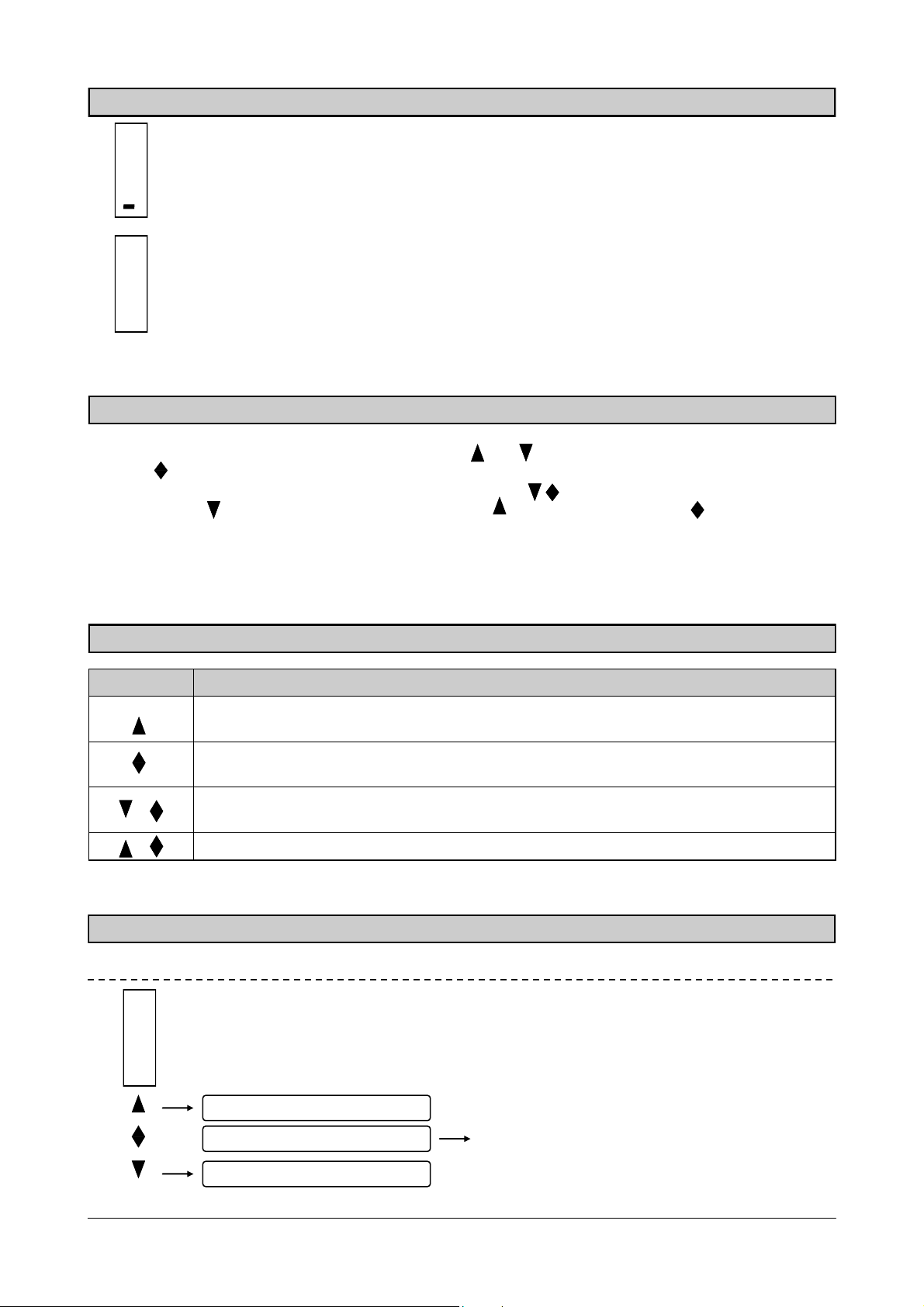
OPERATING MODE
Up the blinking character
Following char selection
Down the blinking character
If the blinking char is the last down, pressing the
key is going to save the value and goes back to
main menu.
RQ device operational handbook
Pag. 3

WEIGHT VIEW AND RESET AND ANALOG OUTPUT ADJUSTMENT
During the startup sequence, the analog output value or the gross weight is shown on the display, depending on the “VISUA” parameter (pag.5).
CHANGING VIEWING BETWEEN ANALOG OUTPUT AND GROSS WEIGHT
To change the view from analog output value to gross weight push and together. The value shown
will blink if the gross weight is on.
4
RESETTING ZERO (reset weight)
(3 seconds)
2
G. weight blinking
Zero calibration
2.
3
Analog Output with 2 decimals
INPUT 1
This procedure is used for set the zero on the scale.
The reset command cannot be executed under these conditions:
Unstable weight.
Gross weight higher or lower of the 10% of the maximum load (depending on the original zero calibra-
tion). If this is the case, you have to access calibration menu and execute calibration.
The weight reset is saved when the device is turned off.
Analog output value and weight value correction
In analog output viewing
o
(3 seconds)
ANALOG OUTPUT VALUE MODIFICATION:
By keeping the key or the key pressed for 3 seconds when you are viewing the analog output, you
gain access to the modification of the analog output value; on the display the value start to grow or shrink
depending on the key pressed. Once the destre value has been reached leave the key and after 1,5 seconds there will be a blinking on the display, the value will be assigned to the analog output, weight will
be modified and you are going to exit from the procedure.
The analog output value and weight can be modified within 10% of the maximum load; on reaching of the
maximum value “MAX “ will appear on display, with the minimum value “ MIN”.
EXAMPLE:
With a 3,00 Volt analog output, the value shown on display will be 3.00.
By pressing after 3 seconds you can see in the display the value growing from 3.01 to 3.02, 3.03 and so
on…. While the analog output will remain to 3.00 Volt. When the destre value is reached (i.e. 3,15 V) the
control can be released. After 1,5 sec. you’ll see the display blinking and the value will be modified and
so the weight.
This modification is limited to the 10% of the maximum load so, in this scenario, the value will change
from 3.30 (maximum) to 2.70 (minimum) starting from 3.00. Once the maximum value is reached the si-
gnal “MAX “ to make the operator understand that any further change is not possible (the same will happen for the lower limit, but in this case the message is “ MIN”).
To execute changes over the 10% limit a new calibration as to be done or the lower limit of the analog
output in the main menu has to be changed.
Open function and starts to
change characters on display
Pag. 4
RQ device operational handbook
 Loading...