

Page 1
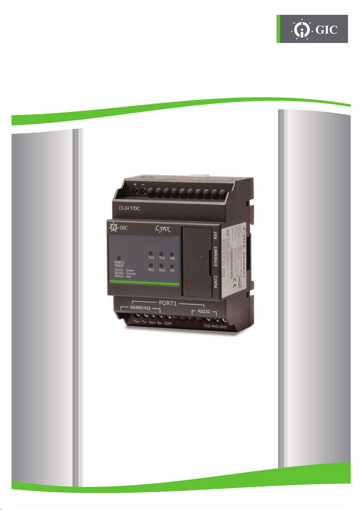
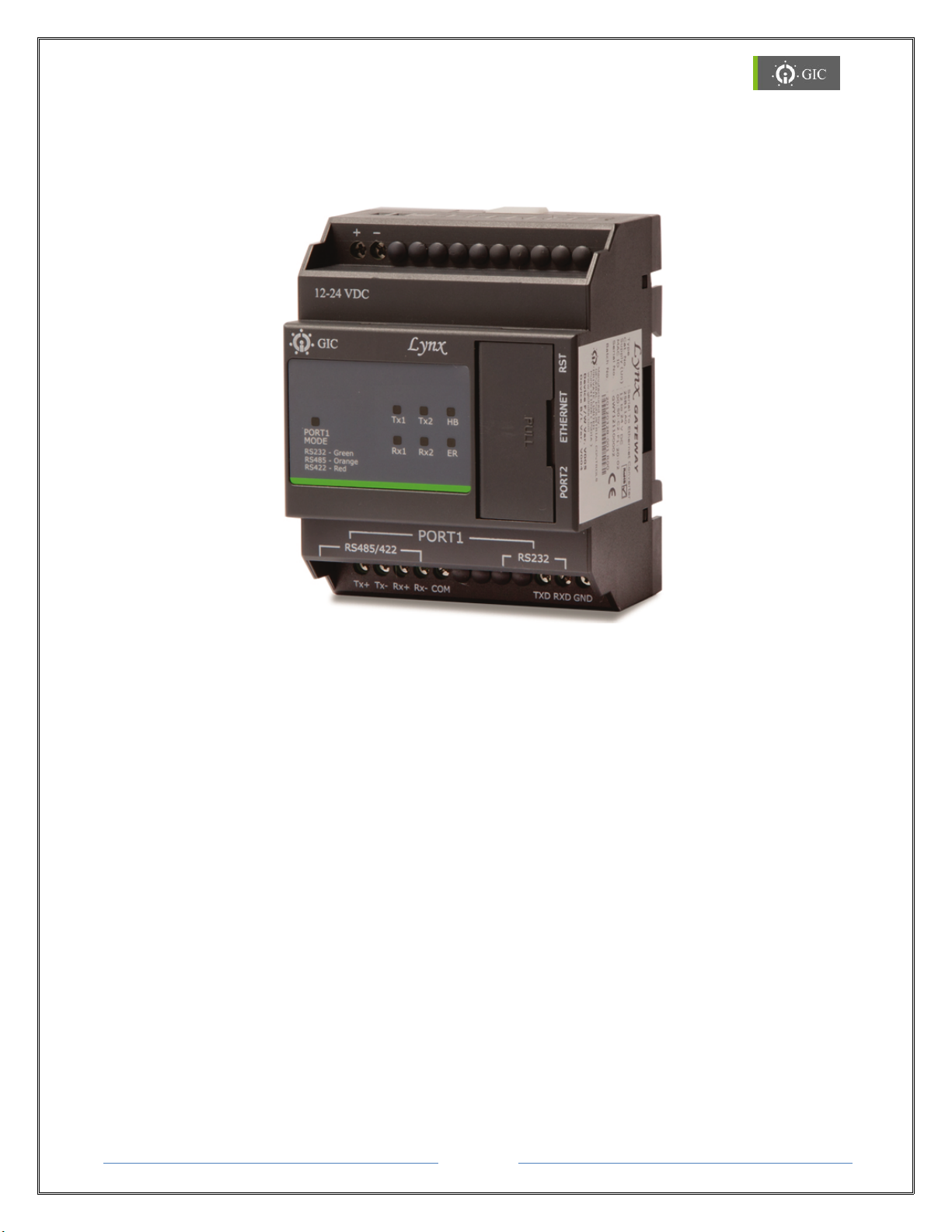
SERIAL TO ETHERNET
Lynx
User Manual
8888
Page 2

www.gicindia.com
Lynx
Table of Contents
1. Introduction 3
1.1. Features 3
1.2. Application 3
2. Knowing the Product 4
2.1. Serial Interface Connection 5
2.2. Ethernet Interface Connection 7
2.3. LED Indications 8
2.4. Reset Switch Functionality 9
3. Working with the Device 11
3.1. MAC ID 11
3.2. IP Address 11
4. Software Installation 13
4.1. Lynx Locator Utility 16
5. Assigning IP Address 18
5.1. Factory Default Settings 18
5.2. Device Configuration Settings 19
6. Settings 20
6.1. Factory Default Settings 20
6.2. Device Configuration Settings 21
7. Technical Specifications 26
8. Mechanical Dimensions 27
8.1. Din Rail Installations 27
9. FAQ’S 28
Page 2
Gateway
Page 3

www.gicindia.com
Lynx
Caution:
Read this manual completely and gather all information on the unit.
For configuring or modifying the IP Address, please contact your network
administrator.
Warning:
Only an expert should change these parameters or settings.
User must definitely know the consequences the changes will have.
This unit must not be operated with removed covers or lids.
Do not attempt to disassemble the unit. There are no user serviceable parts inside.
Do not drop, knock or shake the unit, rough handling above the specification may
cause damage to internal circuit boards.
Do not use harsh chemicals, cleaning solvents or strong detergents to clean the unit.
Do not expose the unit to any kind of liquids. The unit is not waterproof. Keep the
unit within the specified humidity levels.
Do not use or store the unit in dusty, dirty areas.
Page 3
Gateway
Page 4

www.gicindia.com
Lynx
1. Introduction
Lynx Gateway is a Serial to Ethernet Protocol Converter providing communication between
Modbus RTU/ASCII Serial devices & Modbus TCP network devices. It supports various
operating modes & can act as Master or Slave. It supports RS 232, RS 422 and RS 485 &
one Ethernet port providing 10/100Mbps through a standard Ethernet connector. Ethernet
side can be configured either as Client or Server.
It intelligently converts the data between Modbus TCP (Ethernet) and Modbus RTU/ASCII
(serial) devices. By enabling Background communication option it is possible to speed up
the data flow at Serial/Ethernet side thus providing seamless integration of Ethernet and
Serial Modbus devices. It can be configured via web-interface or by Lynx gateway utility. It
also provides remote firmware upgradation.
1.1 Features
Supports Modbus RTU/ASCII (Master/Slave) & Modbus TCP (Client/Server) Protocol
Serial interface supports RS-232, RS 422 and RS485 network.
Ethernet interface supports 10/100Mbps with Auto Negotiation
Ethernet Protocols: BOOTP, TFTP, ARP, DHCP, AUTO/IP, ICMP, TELNET, HTTP server
Serial Baud rate supports from 300 bps to 115.2 Kbps.
Static or dynamic IP configuration via DHCP
Integrated HTTP server for device commissioning and configuration via web browser
Isolation between power supply and communication ports
Remote Firmware Upgrade
LED Indications
1.2 Applications
A few of the different types of serial devices supported by the Serial to Ethernet converter
are listed below:
PLC / HMI / SCADA
Ethernet / Serial based Device monitoring and control system.
Industrial Automation
Data Loggers
Telecommunication Equipment
Security Alarms and Access control systems
Hand Held Instruments
CNC Controllers
Page 4
Gateway
Page 5
www.gicindia.com
Lynx
2. Knowing the Product
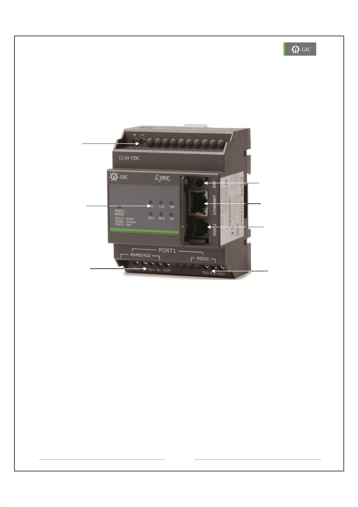
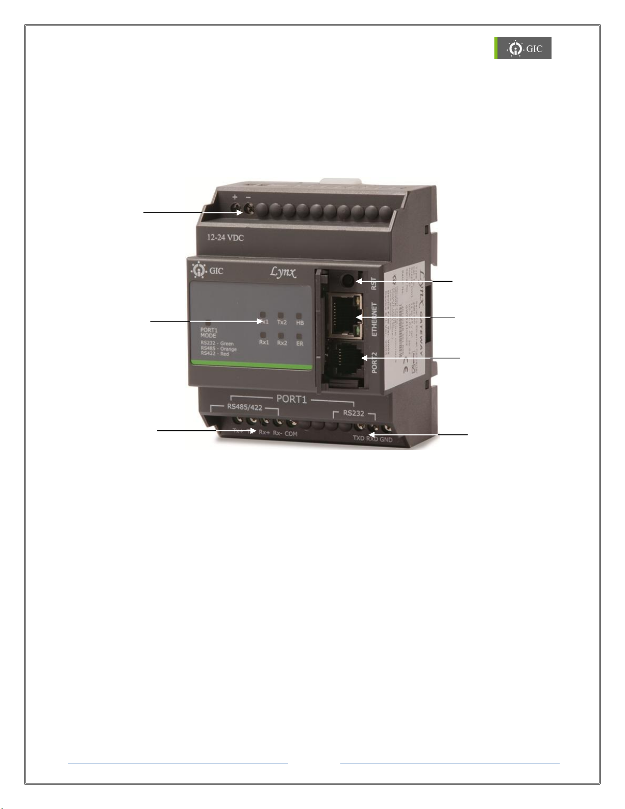
The Lynx Gateway works on a 12 - 24 VDC supply. There are 2 serial ports (One RJ11 port
for RS 232 & screw terminals for RS 232/422/485) and one Ethernet port provided on the
device for connecting devices for communication. There is a Reset (RST) switch provided on
the device which serves different purposes. There are 7 LEDs indicating the transmission &
reception of data as well as the status of other signals and states.
Power Supply
Reset Switch
LED Indications
Serial Port 1
(RS 422/485)
Ethernet Port
Serial Port 2 (RJ 11)
Serial Port 1
(RS 232)
Page 5
Gateway
Page 6
www.gicindia.com
Lynx
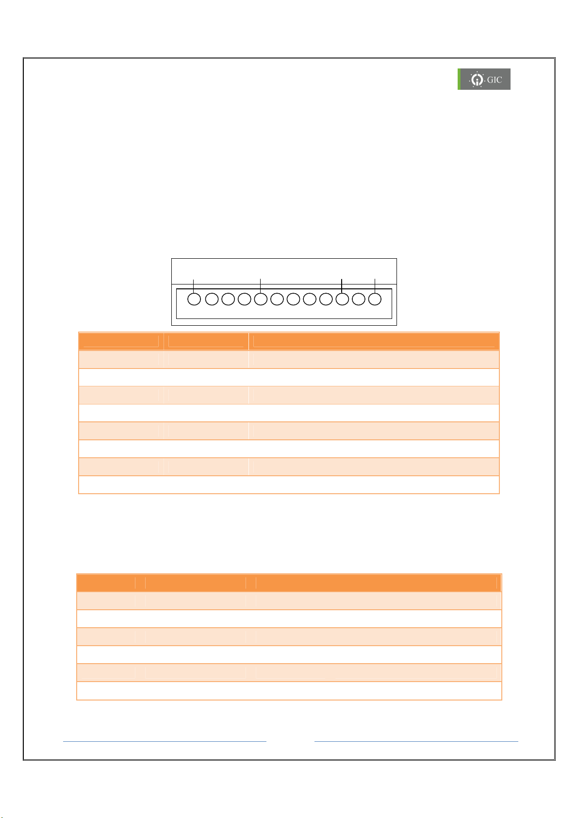
2.1. Serial Interface Connections
RS 232
RS
485/422
PORT 1
There are two serial ports provided on the device for communication:
Port 1 & Port 2.
Port 1 (RS232/RS422/RS485):
Port1 is used to connect Master/ Slave devices at serial side. The serial device interface can
be RS-232, RS-485 & RS-422 and the connections are screw terminals. This following
section along with the diagrams describes in detail the practical methods for connecting
devices at the serial end for the RS-232 & RS 422/485 Serial interface.
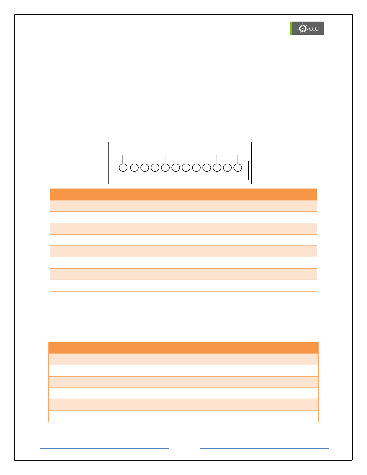
Serial Interface Signals for Port 1:
Tx+ Tx- Rx+ Rx- COM
Signal Direction Primary Function
TXD Out Transmit Data for RS232
TXD RXD GND
RXD In Receive Data for RS232
GND NA Ground for RS232
TX+/D+ Out Differential Transmit Data(+) for RS422/RS485
TX-/D- Out Differential Transmit Data(-) for RS422/RS485
RX+ In Differential Receive Data(+) for RS422
RX- In Differential Receive Data(-) for RS422
COM NA Ground for RS422/RS485
Port 2 (RJ11):
This is an optional port for debugging. RJ11 port is provided for the RS232 connections.
Serial Interface Signals for Port 2:
Pin No Signal Name DIR Primary Function
1 NC - 2 TXD Out Transmit Data for RS232
3 RXD In Receive Data for RS232
4 NC - 5 GND GND Ground for RS232
6 NC - -
Page 6
Gateway
Page 7
www.gicindia.com
Lynx
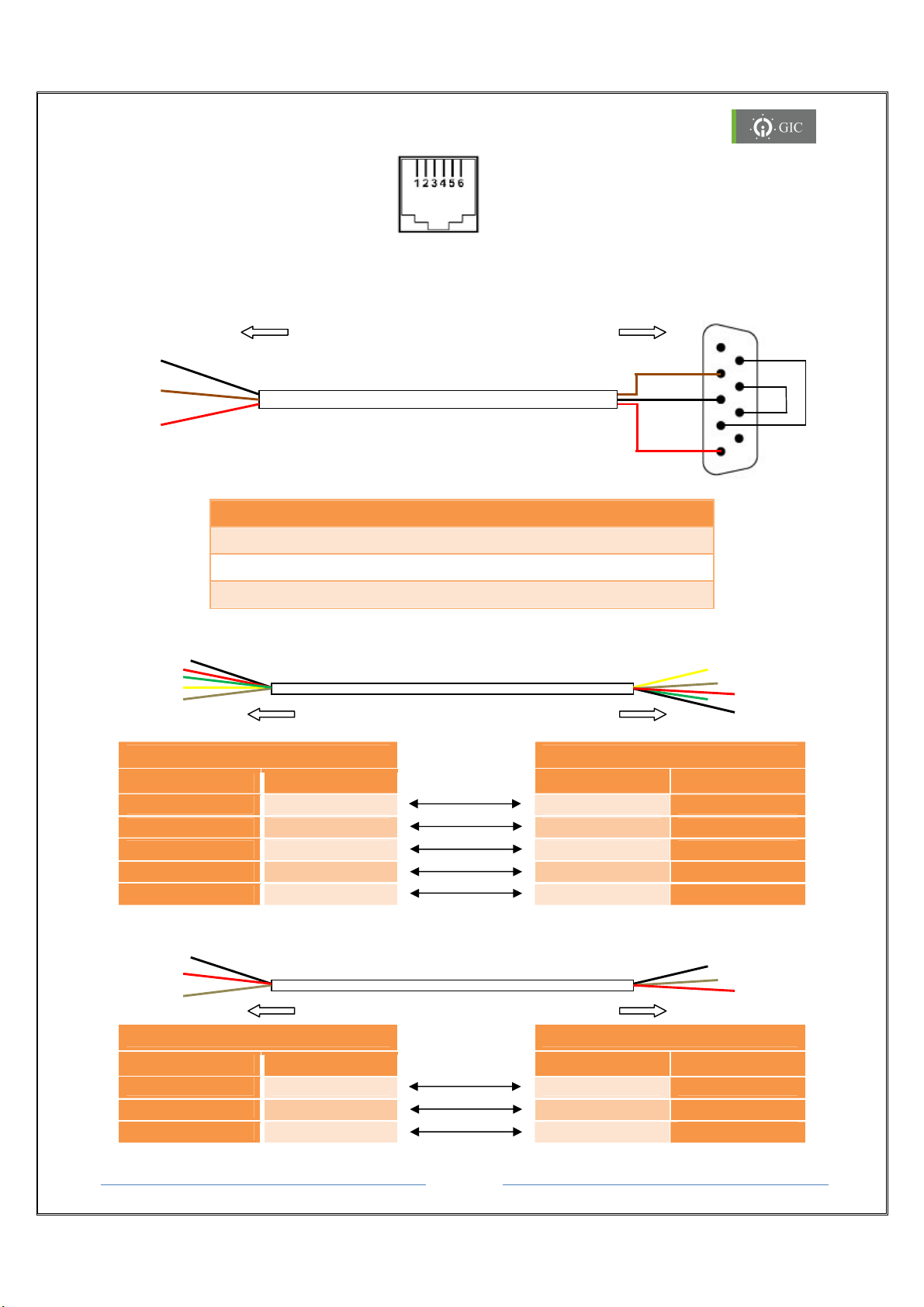
RS232 Cable Diagram:
Signal
Colour
Colour
Signal
COM
Black
Black
COM
To PC / Device
DB9 Female
1
5
6
To
Gateway
To
Gateway
To Device RS 422 Port
To
Gateway
To Dev
ice RS 485 Port
RJ 11 Connector
RS 232 Port
Note: The above color code is only used for reference
Signals Pin No Colour
TXD 2 Brown
RXD 3 Black
GND 5 Red
RS422 Cable Diagram:
From Lynx S2E To Device
1
6
9
5
9
DSR
RTS
CTS
DTR
Pin Out
Signal
TX+ Yellow
TX- Brown
RX+ Red
RX- Green
COM Black
RS485 Cable Diagram:
From Lynx S2E To Device
TX+ Red
TX- Brown
Colour
Page 7
Colour
Yellow RX+
Brown RX-
Red TX+
Green TX-
Black COM
Red TX+
Brown TX-
Signal
Gateway
Page 8
www.gicindia.com
Lynx
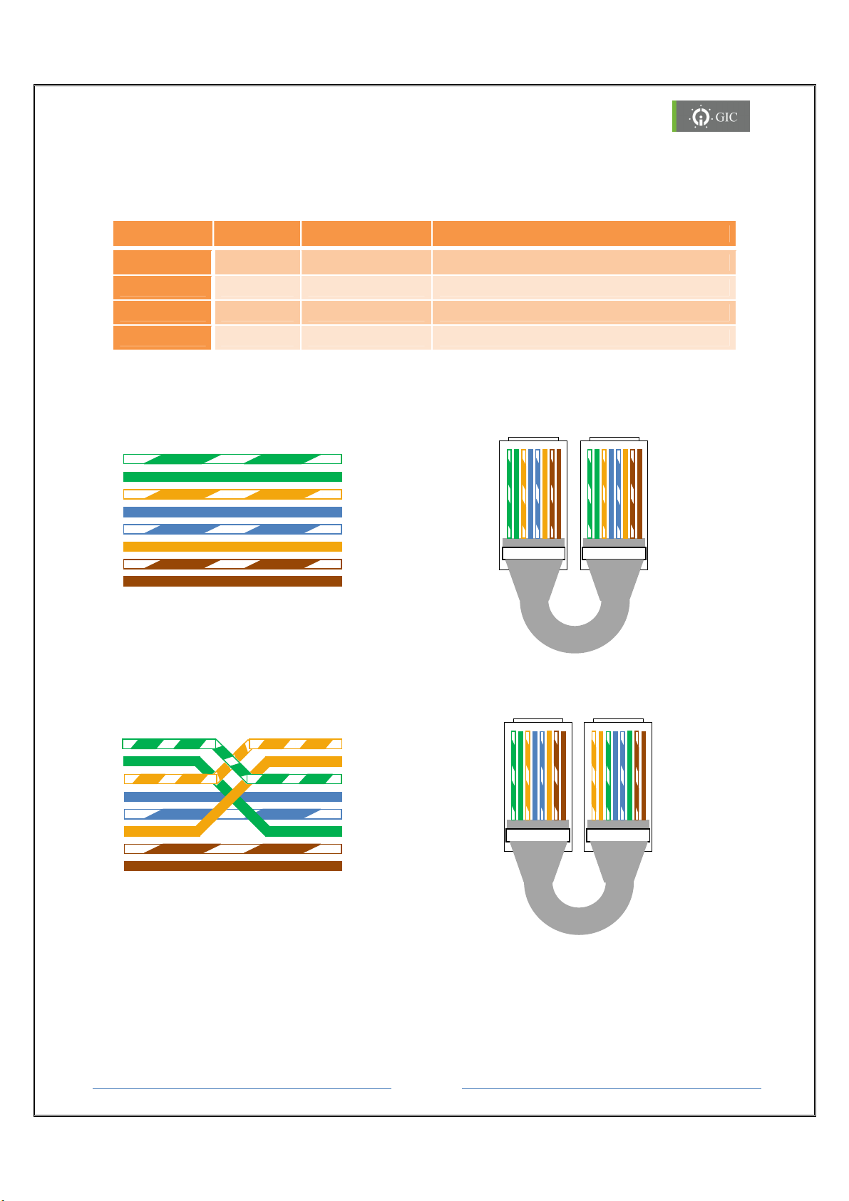
2.2. Ethernet Interface Connections
2 3 4 5 6 7 8
Tx-
1
2
4 5 6
7
8 7 6 5 4 3 2 1 8 7 6 5 4 3 2 1
1 2 3 4 5 6 7 8
1 2 3 4
5
7
Cross Over
PC PC
7 6
7 6
Lynx Gateway supports 10/100Mbps Ethernet through RJ-45 (10BaseT/100BaseTX)
connector. It also supports auto negotiation.
Signal Pin Direction Primary Function
TX+ 1 Out Transmit Data +
TX- 2 Out Transmit Data -
RX+ 3 In Differential Ethernet Receive Data +
RX- 6 In Differential Ethernet Receive Data -
RJ45 Cable Diagram:
PC
Tx+
Rx+
3
Rx-
8
Straight Through Cable
Tx+
Tx-
Rx+
Rx-
6
8
Cross Over Cable
Hub
Rx+
1
Rx-
Tx+
Tx-
Tx+
Tx-
Rx+
Rx-
Page 8
4 3 2
8
5
1
4 3 2
5
1
8
Gateway
Page 9
www.gicindia.com
Lynx
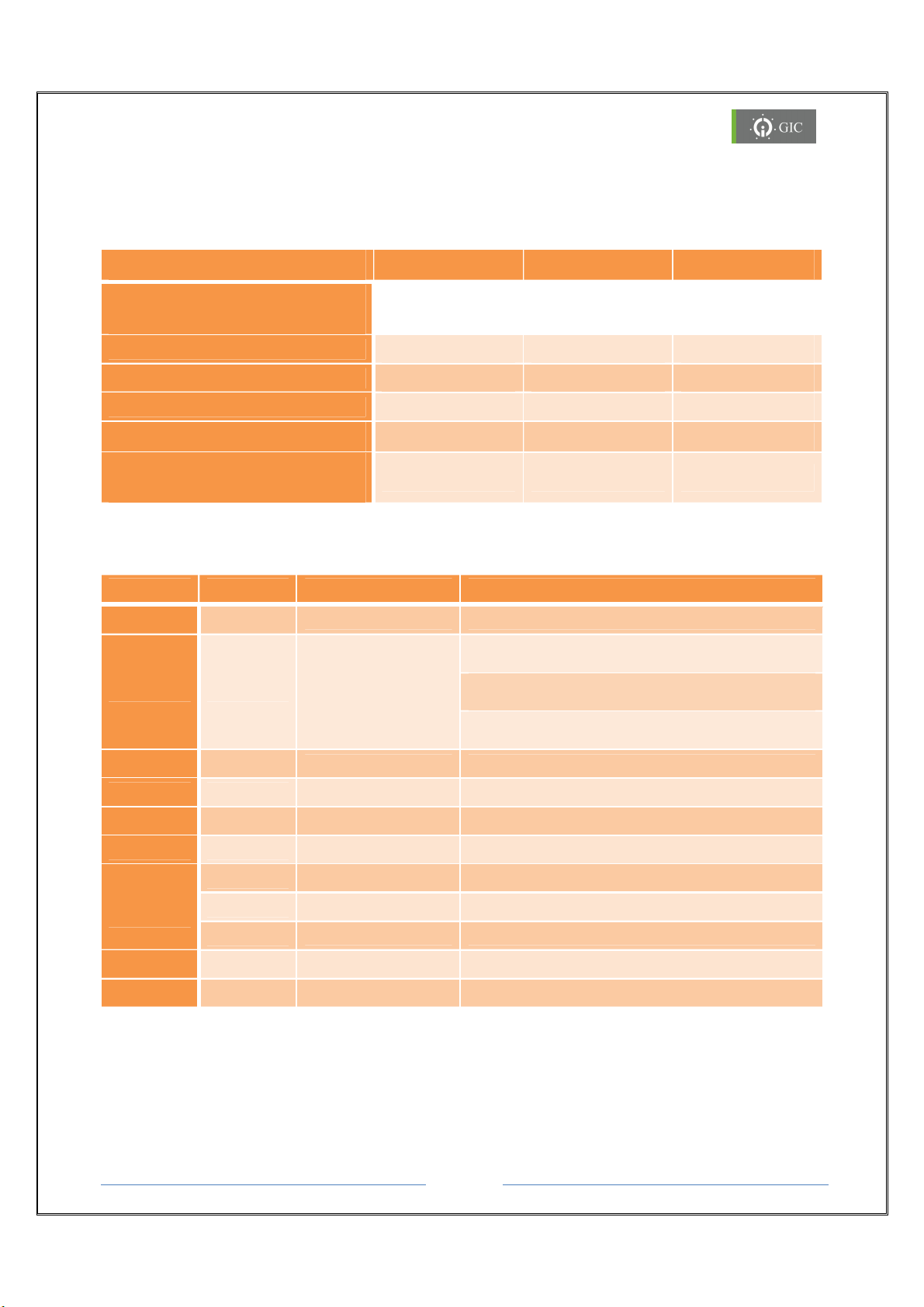
2.3. LED Indications
IP Address Conflict Error
LED Indications for Settings
ERROR LED HB LED MODE LED
Serial Port 1 Interface
Selection
RS 232 Interface
RS 422 Interface
RS 485 Interface
Factory Default Settings
Firmware Downloading /
No Firmware
Continuous ON Blinking Green
Continuous ON Blinking Red
Continuous ON Blinking Orange
Continuous ON Blinking -
Continuous ON Continuous ON NA
LED Indications during Run Time
LED Colour Status Function
HB Green
ERROR Red
TX1 Green
Blinking Healthy Status
IP Address Search Modes
(100ms ON and 100ms OFF)
Blinking
Blinking Serial Port-1 Data Transmit
(500ms ON and 500ms OFF)
Reset Key Fail
(1s ON and 10s OFF)
RX1 Green
TX2 Green
RX2 Green
Green
Port 1
Mode
Orange
Link Yellow
Activity
Orange
Red
Blinking Serial Port-1 Data Receive
Blinking Serial Port-2 Data Transmit
Blinking Serial Port-2 Data Receive
Continuous ON RS232 selected
Continuous ON RS422 selected
Continuous ON RS485 selected
Continuous ON Link (socket connection made)
Random Flashing Activity (network 10/100mbps)
Page 9
Gateway
Page 10
www.gicindia.com
Lynx
2.4. RST Switch Functionality
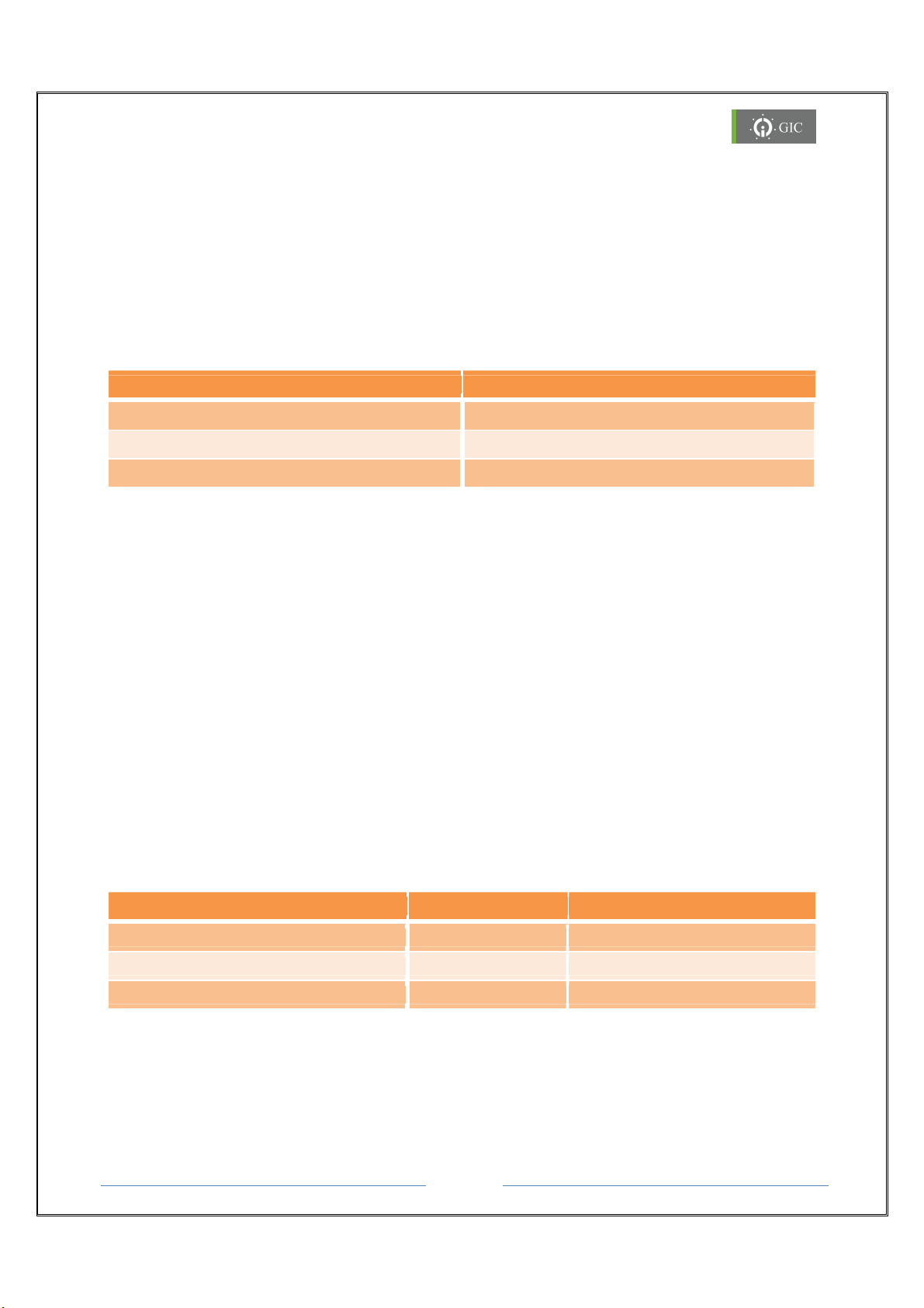
The Reset (RST) key provided on the device is used for the following purposes:
1. Serial Port 1 Interface Selection
2. Restore Factory Default Settings
Depending on the time duration for which the RST key is pressed at power on, the particular
mode will be selected
Key Press Interval (T) Selected Mode
2 sec < T < 8 sec Serial Interface Selection Mode
8 sec < T < 12 sec Default Factory Settings Selection
12 sec < T Reset (RST) Key Fail Error
2.4.1 Serial Port1 Interface Selection
Serial Interface Selection Mode is used to select the different Serial Interface modes for
PORT1. The serial interfaces available for port 1 are RS232, RS422 and RS485. Ensure that
the Serial Selection Mode is ‘Unlocked’ in the Driver 1 settings page on the Web
browser.
To configure the serial interface option,
1. Press RST switch & then power ON. Keep the RST switch pressed for 2-8 sec.
2. Error LED glows continuously during Serial Interface Mode selection.
3. Heart Beat (HB) LED starts blinking (150 ms ON & 150 ms OFF) indicating that the
device has entered into Serial Selection Mode.
4. Press and release RST switch to select a particular serial interface option which is
indicated by the MODE LED.
Depending on the number of times the RST key is pressed after the HB LED starts blinking,
the particular mode will be selected.
No. Of times RST key is pressed LED Color Interface Mode
1 Red RS422 Interface mode
2 Orange RS485 Interface mode
3 Green RS232 Interface mode
5. After selecting a particular serial interface, user has to wait for 5 seconds to confirm
the selection which is indicated by fast blinking MODE LED in Orange color. The
device will then run in normal mode which is indicated by the blinking Heart Beat
(HB). (800 ms ON and 800 ms OFF).
6. The MODE LED glows continuously in the selected serial interface color.
Page 10
Gateway
Page 11

www.gicindia.com
Lynx
The user can lock/unlock the serial selection mode through the web server.
In “Driver1 Settings” page, select “Lock” option to lock/unlock the serial option selected
using RST key.
If Port1 selection is locked and someone is trying to change the serial interface by pressing
RST key, the device will not allow the change and will enter the RUN mode which is
indicated by the blinking MODE LED (for 5 sec) in its programmed serial interface color.
2.4.2 Restore Factory Default Settings
To restore Factory Default Settings of the device,
1. Press RST switch & then power ON. Keep the RST switch pressed for 8-12 sec.
2. Error LED glows continuously during Serial Interface Mode selection.
3. Heart Beat (HB) LED start's blinking (50msec ON & 50msec OFF) indicating that the
device has entered into Factory Default Mode.
4. To confirm the Factory Default settings, again press the Reset (RST) key within the
next 5 seconds.
5. When the settings are restored to factory default the MODE LED starts blinking
(Orange). If the RST key is not pressed within 5 seconds, the device exits the restore
factory default settings mode.
6. After 5sec device runs in normal mode which is indicated by blinking of HB LED for
800msec ON & 800msec OFF. MODE LED glows continuously in green color because
RS232 is the default serial interface mode.
Page 11
Gateway
Page 12
www.gicindia.com
Lynx
3. Working with the Device
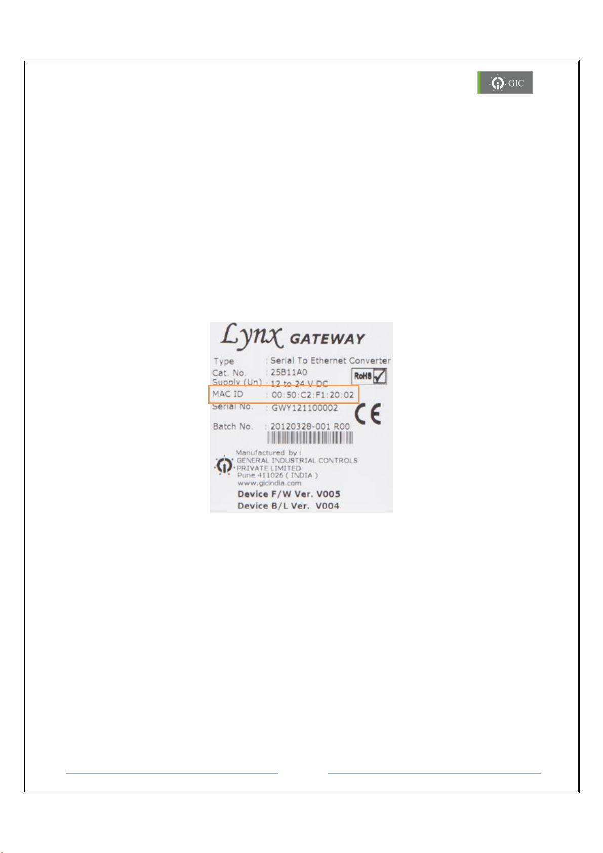
3.1 MAC (Media Access Control) ID:
A Media Access Control address (MAC address) is a unique identifier assigned to network
interfaces for communications on the physical network segment. MAC addresses are most
often assigned by the manufacturer of a network interface card (NIC) and are stored in its
hardware, the card's read-only memory, or some other firmware mechanism. The MAC
address usually encodes the manufacturer's registered identification number.
Locating the MAC (Media Access Control) ID:
The MAC ID of the Lynx Serial to Ethernet converter is printed on the label attached to the
device. Please refer this MAC ID while assigning IP address to the device through DHCP
server or while configuring the device.
3.2 IP Address
Each TCP/IP node on a network host has a unique IP address. This address provides the
information needed to forward packets on the local network and across multiple networks.
IP addresses are specified as x.x.x.x, where each x is a number from 1 to 254; e.g.,
192.0.1.99. The Device Server must be assigned a unique IP address to use TCP/IP network
functionality.
When the Lynx Gateway is powered ON for the first time and connected to an active
network, no IP address in assigned to the device. The device is in Factory Default Mode
which is indicated by continuous blinking of ERROR LED (100ms ON & 100ms OFF).
Device is in DHCP mode
Page 12
Gateway
Page 13
www.gicindia.com
Lynx
4. Software Installation
1. Insert the product CD in the CD-ROM drive. The CD will run automatically and the
installation window will be displayed on the screen. If the CD does not run automatically,
open the CD by right clicking on the CD and select ‘open’.
2. Double click on the ‘Setup.msi’ program to begin the installation process.
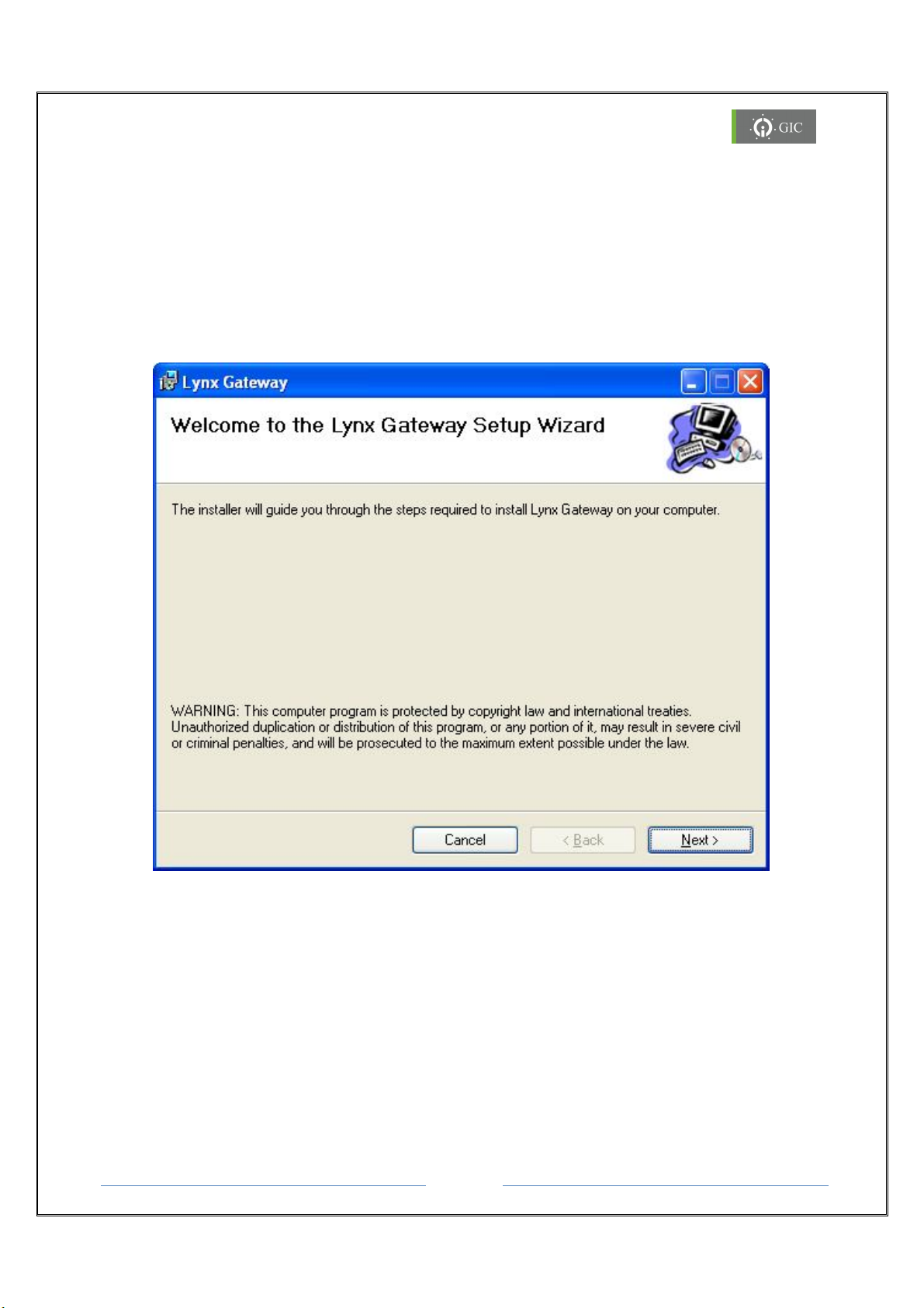
3. When the installation window appears on the screen click on ‘Next’ to continue
4. A ‘Welcome to the Lynx Gateway Setup Wizard’ window will be displayed on the
screen. Click on ‘Next’ to continue.
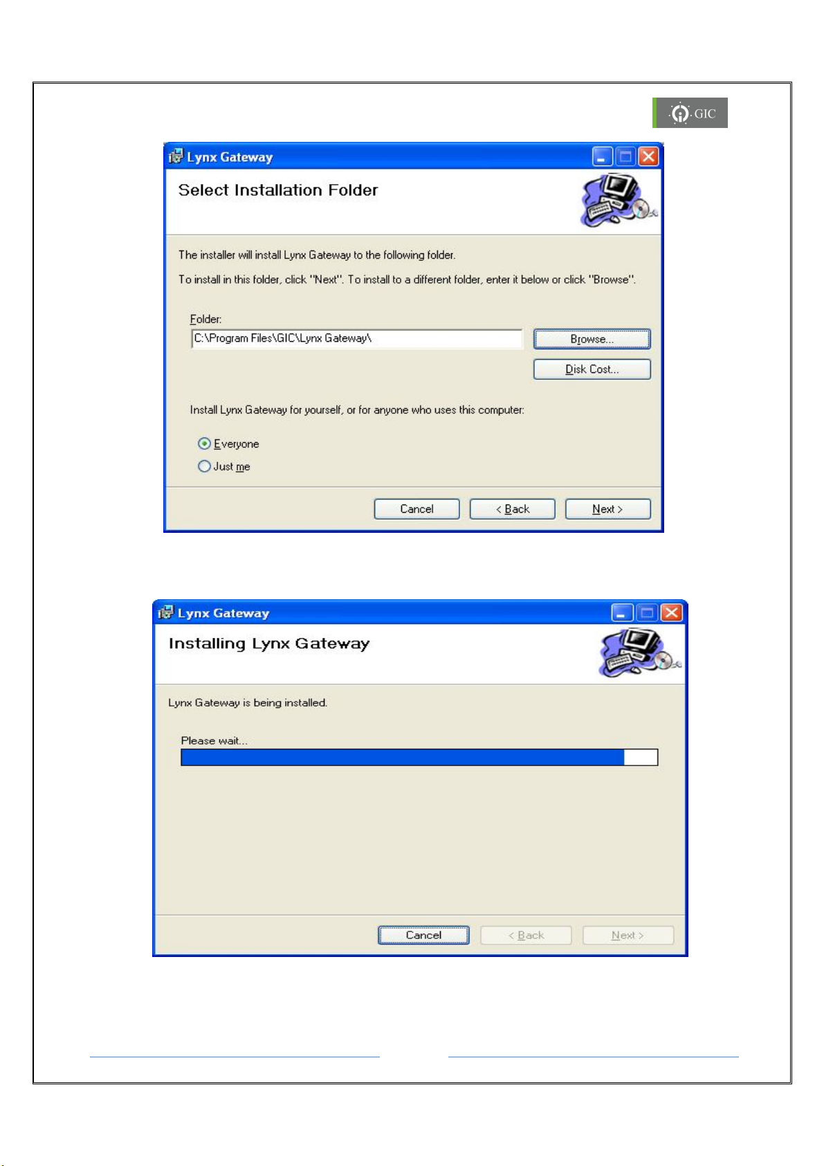
5. When the ‘Select Installation Folder’ window appears on the screen, click on ‘browse’ to
select the folder where the software is to be installed. By default the software will be
installed in (Drive Letter:\Program Files\GIC\Lynx Gateway)
The ‘Disk Cost’ option shows the available drives to install the software along with required
and available space on each drive.
The software may be installed only for the current user or for all users.
Select the correct options and click on Next to continue.
Page 13
Gateway
Page 14
www.gicindia.com
Lynx
6. The ‘Installing Lynx Gateway’ Window will appear on the screen indicating the
installation process has started. The procedure will take few seconds to complete.
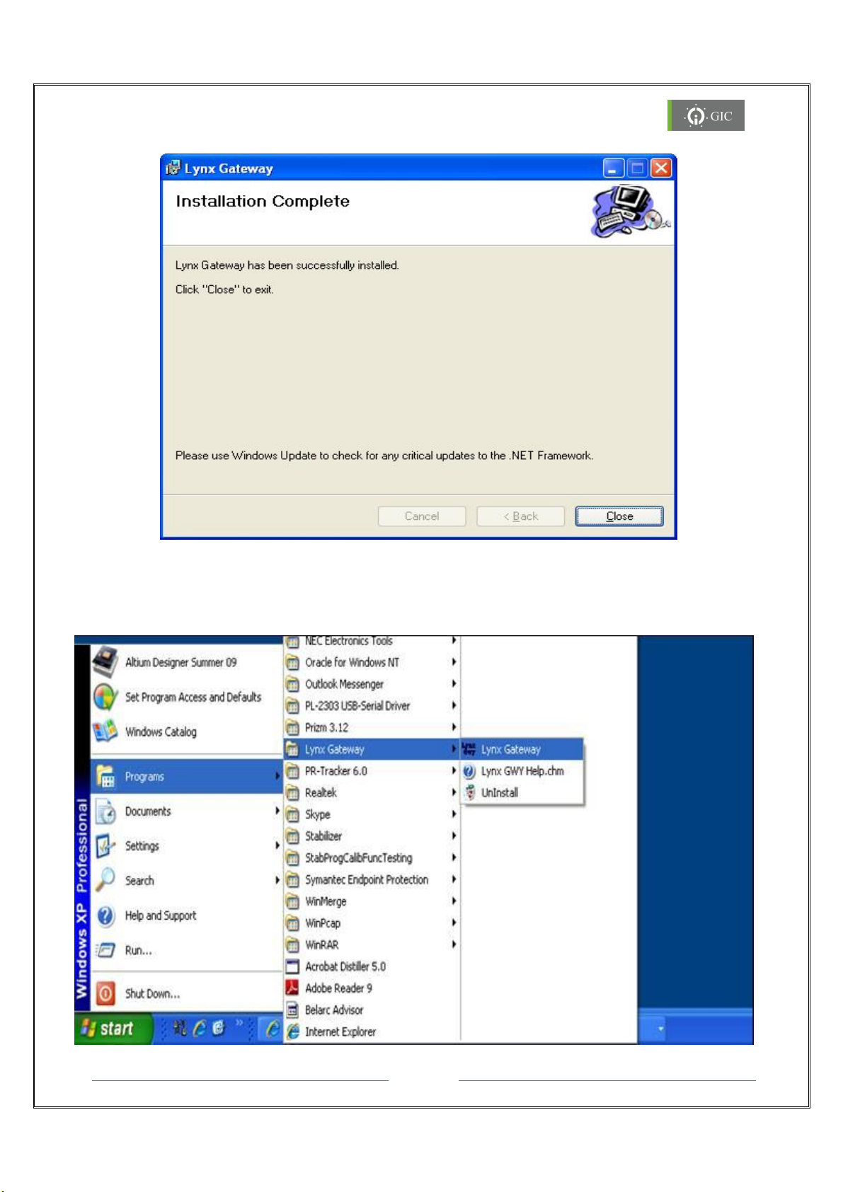
7. When the installation is complete, ‘Installation Complete window’ will appear on the
screen indicating that the Lynx Gateway has successfully installed. Click on ‘Close’ to exit
the wizard.
Page 14
Gateway
Page 15
www.gicindia.com
Lynx
8. To launch the Lynx Gateway software:
Double click on the Lynx Gateway Icon on the desktop screen or
Click on Start → Programs → Lynx Gateway → Lynx Gateway
Page 15
Gateway
Page 16
www.gicindia.com
Lynx
4.1 Lynx Locator Utility:
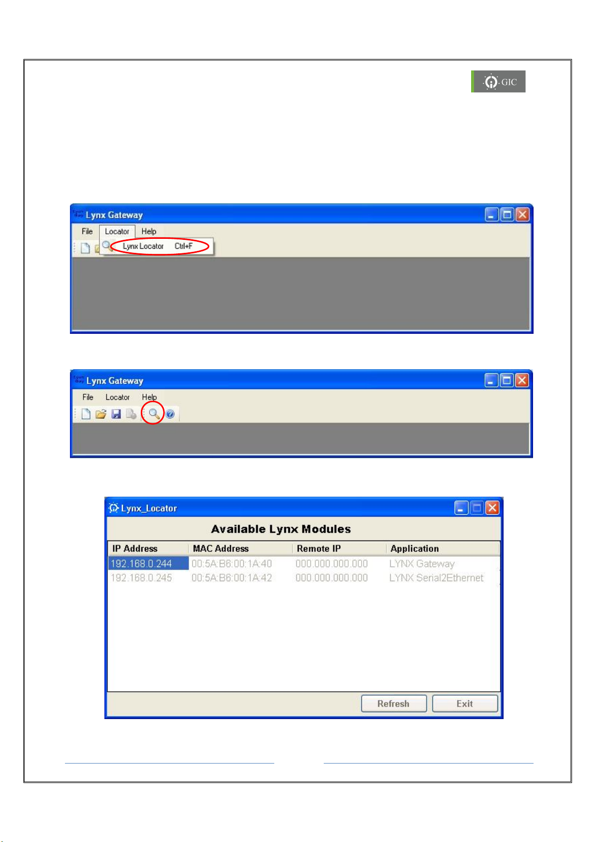
Lynx Locator is a utility that locates all the Lynx devices in the network and displays them
in a window along with their IP Address, MAC Address, Remote IP Address and Application
title.
1. To open the utility click on Locator → Lynx Locator(Ctrl+F) in Lynx Gateway
Software OR
2. Click on the short cut placed on the tool bar.
3. The following window with 4 fields is displayed.
Page 16
Gateway
Page 17

www.gicindia.com
Lynx
a. IP Address : This field indicates device IP address.
b. MAC Address : This field indicates hardware address of the device.
c. Remote IP : This field indicates IP address of PC to whom Lynx Serial To
Ethernet device has connected.
d. Application Title : This field indicates the name that has been assigned to the
device by the user. If user has not assigned any name to the
device then default name of device will be displayed.
4. Click on Refresh tab to locate the devices that are present in the network.
5. Note the IP address corresponding to the MAC Address & Application Title of the
device.
6. If the device is Factory Default Mode and can't be located in the utility, then change
the IP address of the PC to AutoIP range 169.254.0.1 to 169.254.255.254 & then try
to locate the device.
7. If the device contains some other IP address which is not in the same network as
the PC, device won't be located in the utility. In such case Restore Factory Default
settings of the device using the RST switch as explained in 2.4.2.
8. Exit tab quits the Lynx Locator utility.
Note:
For upgrading Firmware and configuring Driver settings, refer the “Help file” in
the software. Initially Driver1 is configured as Modbus RTU Master and Driver2 as
Modbus TCP server in transparent mode of communication.
Page 17
Gateway
Page 18

www.gicindia.com
Lynx
5. Assigning IP Address
IP address can be assigned to the device through web-server in 3 different ways.
Note: The device is configured for DCHP mode in factory default settings.
1. DHCP/Auto IP mode
In DHCP/Auto IP mode, IP address is assigned to the device if DHCP server is present in
the network. If DHCP server is not present in the network, IP address will be assigned
from the Auto/IP range. In that case follow the procedure as specified in Auto IP mode.
2. Auto IP mode
In Auto IP mode, IP address is assigned to the device by the network from the AutoIP
range 169.254.0.1 to 169.254.255.254. Change the IP address of the PC from the
existing one to the one from the AutoIP range with Sub-net mask 255.255.000.000 and
then locate the device in the locator utility. (Refer 4.1.2)
3. Static IP mode
In static IP mode, you should assign a free IP address to the device and the
corresponding sub-net mask. Care should be taken that the IP address assigned to the
device is in same network as the PC. Also the sub-net mask of the device and PC should
be same.
5.1. If DHCP server is present in the network:
1. A Free IP address in the network is assigned to the device.
2. Error LED indication will stop blinking.
3. Locate the device in Lynx Locator Utility as shown in section 3.2 and observe the
assigned IP address.
4. Enter this IP Address in the address bar of web browser to change the configuration
parameters.
5.2. If DHCP server is not available in the network:
1. If the device is powered ON and DHCP server is not present in the network, then
after 60 seconds the device enters in to Auto IP mode.
2. An IP address from the range 169.254.0.1 to 169.254.255.254 is assigned to the
device
3. Locate the device in the network by using the Lynx Locator Utility.
4. If the device can't be located in Lynx Locator Utility, change the IP Address of the
computer from the existing one to the one from the AutoIP range 169.254.0.1 to
169.254.255.254 with sub-net mask 255.255.0.0
Note:
Device and PC should be in the same Ethernet Network after AutoIP mode.
Note down the initial IP Address & sub-net mask of PC before changing.
Page 18
Gateway
Page 19

www.gicindia.com
Lynx
5. Now, locate the device in the network using the Lynx Locator utility
6. Enter the IP address of the device displayed in the Lynx Locator utility in the address
bar of the web browser.
7. Now again change the IP address to static and configuration settings of the device.
8. Revert back IP address settings of PC, and locate device in Lynx Locator utility with
new assigned IP address.
9. If the IP address assigned to the device and PC are in different networks, device will
not be located in Lynx Locator Utility, press Reset (RST) to restore Factory Default
Settings as shown in section 2.4.2.
Page 19
Gateway
Page 20
www.gicindia.com
Lynx
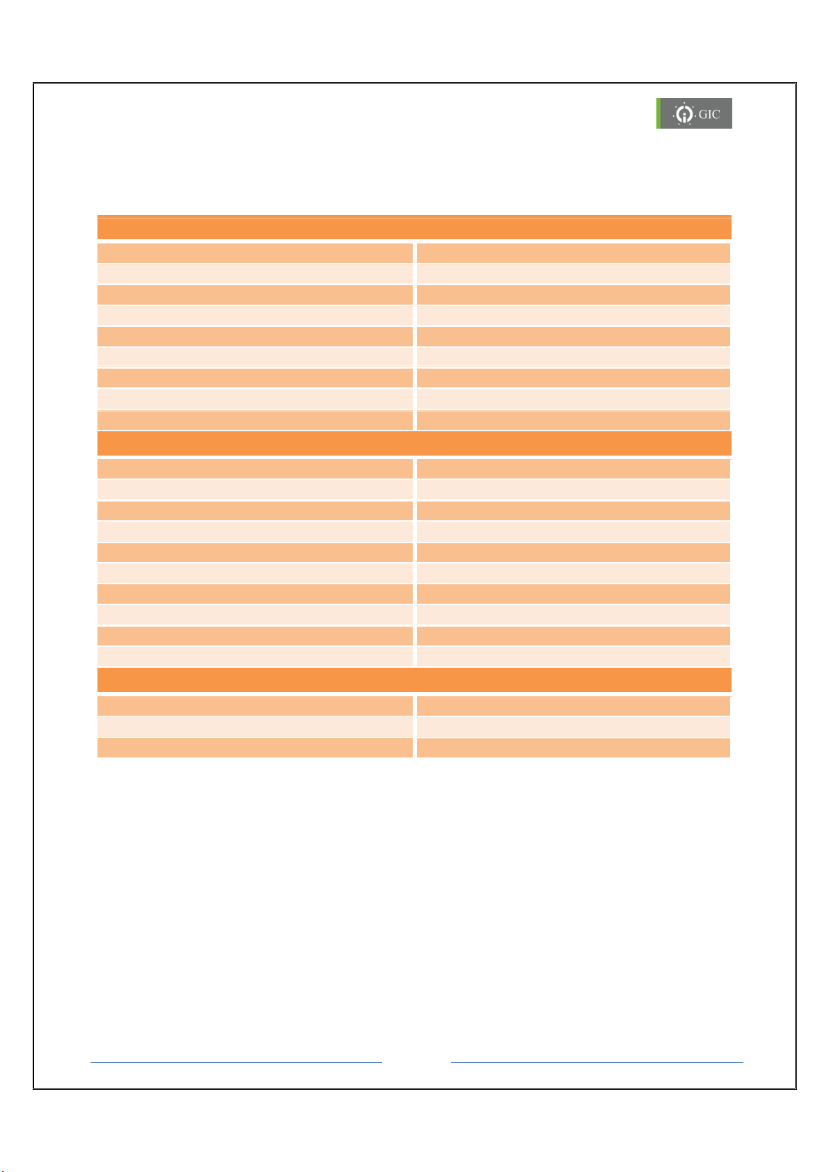
6. Settings
Default Gateway
000.000.
000.000
Communication Mode
6.1 Factory Default Settings:
Driver 1 Settings
Port RS-232
Baud Rate 9600
Data Size 8
Parity None
Stop Bits 1
Response Timeout 1000msec
Delay between polls 500msec
Retry count 1
Slave ID 1
Driver 2 Settings
Port 502
IP mode DHCP
IP address 000.000.000.000
Sub-net mask 255.255.255.000
Remote IP 000.000.000.000
TCP Timeout 0msec
Response Timeout 1000msec
Delay between Polls 500msec
Retry Count 1
Miscellaneous Settings
Module Name LYNX Gateway
Password gateway
TRANSPERENT
Page 20
Gateway
Page 21
www.gicindia.com
Lynx
6.2 Device Configuration Settings:
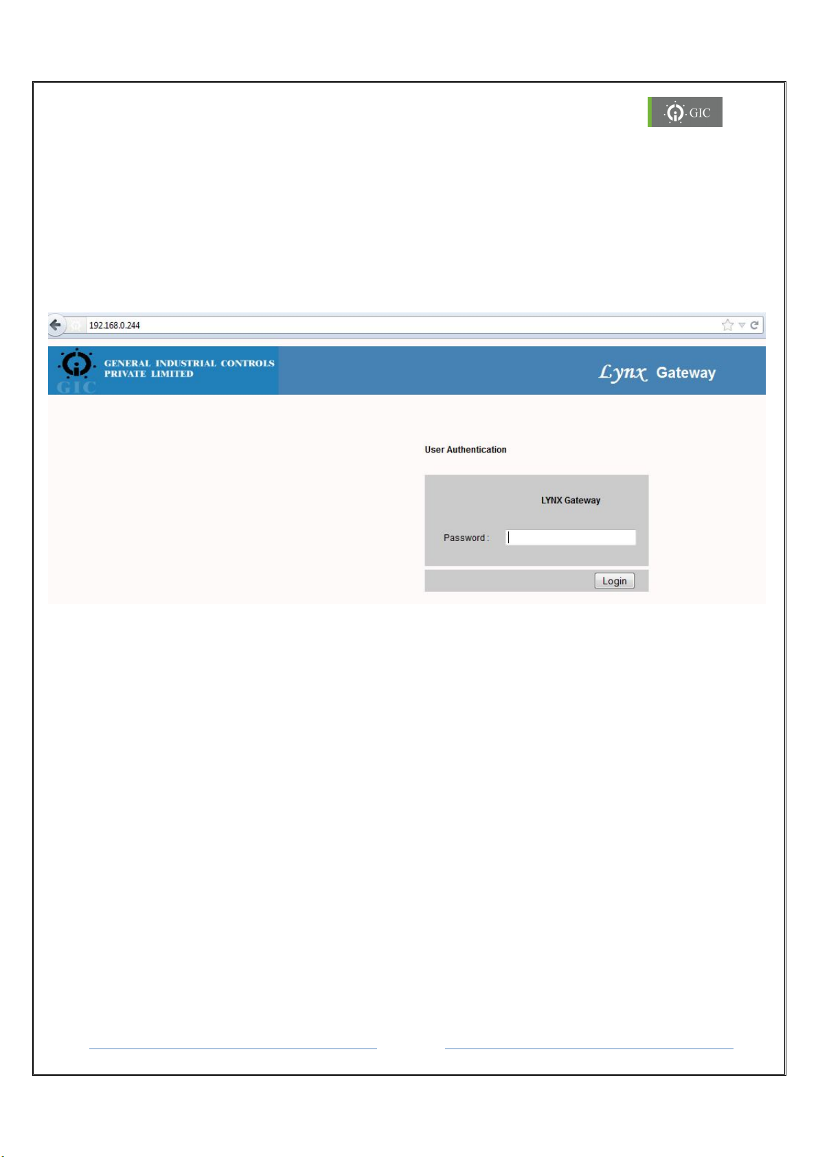
The device current configuration settings can be viewed & edited by accessing the web
server page
1. To access the web server for device type “http://” command followed by IP address
of the device whose configuration settings are to be viewed or edited.
e.g. - http://192.168.0.244
2. The User Authentication page is displayed for authentication.
3. Enter the valid password to access the web server and click on “Login” button.
4. If password is valid then the Home page is displayed or else the same page is
displayed.
Note: Default Password is “gateway”
Page 21
Gateway
Page 22
www.gicindia.com
Lynx
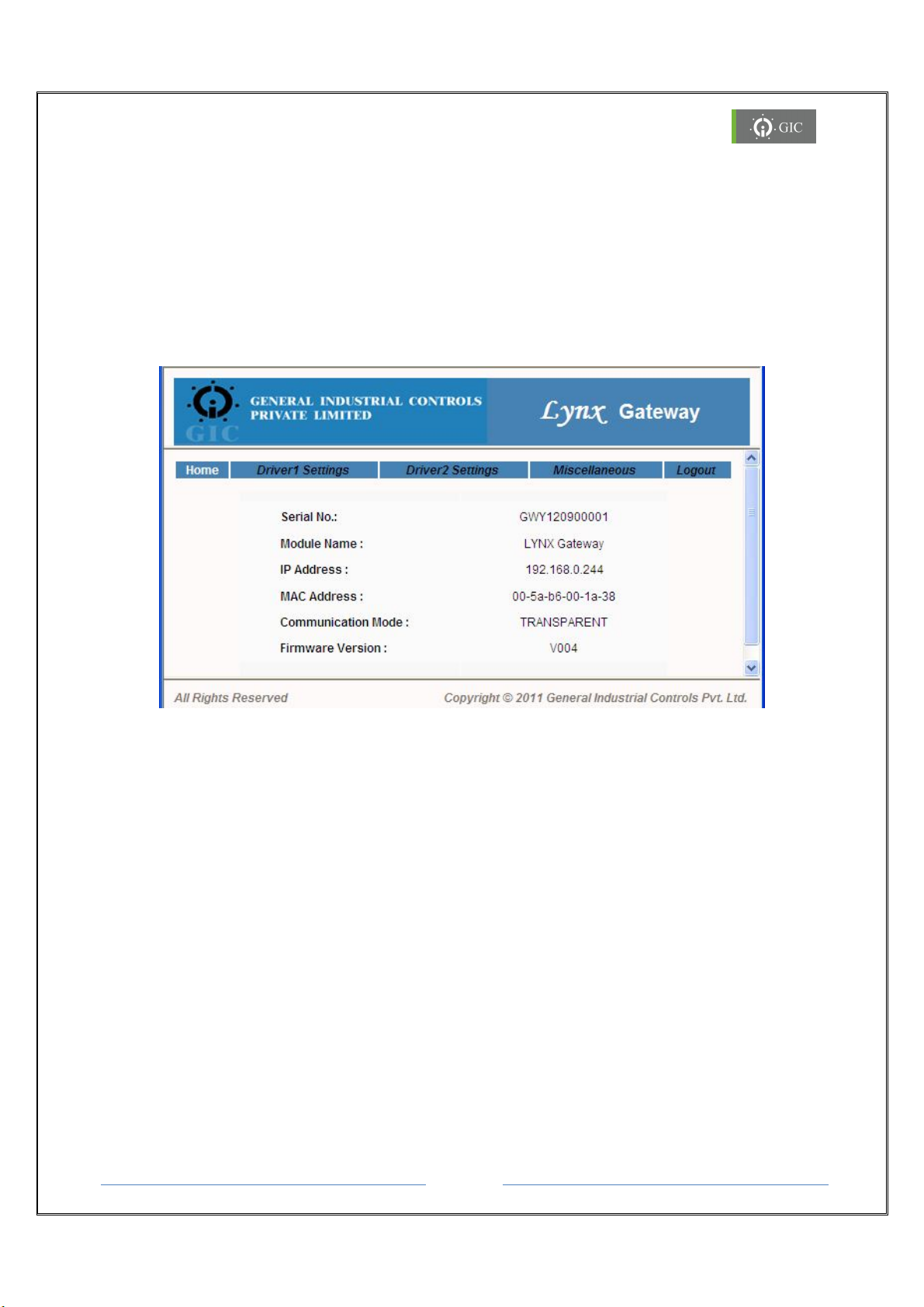
Home Page:
The Home page displays the following device information:
1. Device Serial No
2. Module Name
3. IP Address
4. MAC Address
5. Communication Mode
6. Firmware Version.
Page 22
Gateway
Page 23
www.gicindia.com
Lynx
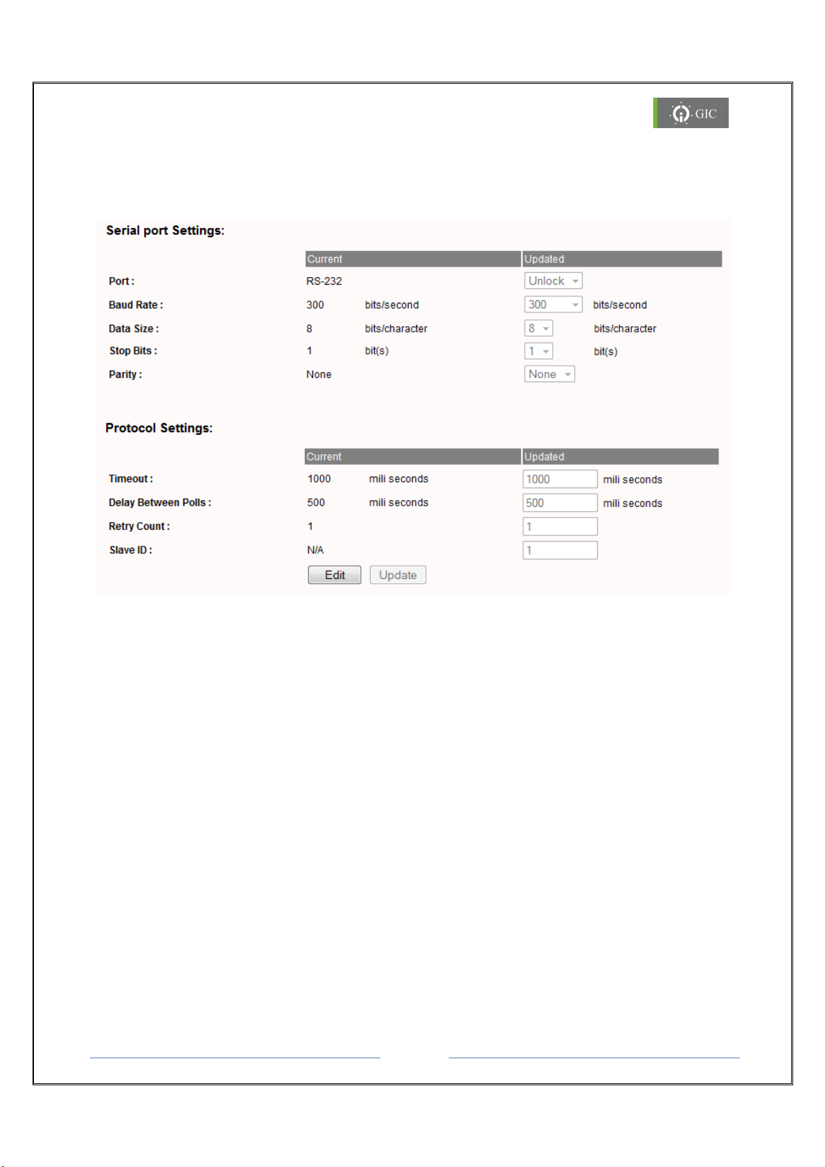
Driver 1 Settings (Serial Port Settings)
Driver1 is used to edit the settings of Modbus RTU/ASCII for both Master/Slave.
Click on the Driver1 Settings tab to view or edit the settings for serial Port 1.
Baud Rate, Data Size, Stop Bits, Parity are the parameters to be updated from the serial
side
Timeout:
Timeout is applicable only for Master/Client driver. It is the time for which the device will
wait for the response from external Slave device.
Delay Between Polls:
Delay between polls is applicable only for Master/Client driver. This is the delay between 2
consecutive requests.
Retry Count:
Retry count is applicable only for Master/Client driver. It is the number of times, the
'requests' will be sent by the device if it does not receive 'response' from the external slave
device. Valid values can be 1 to 10.
Slave ID:
Slave ID is applicable only for Slave/Server driver.
Page 23
Gateway
Page 24
www.gicindia.com
Lynx
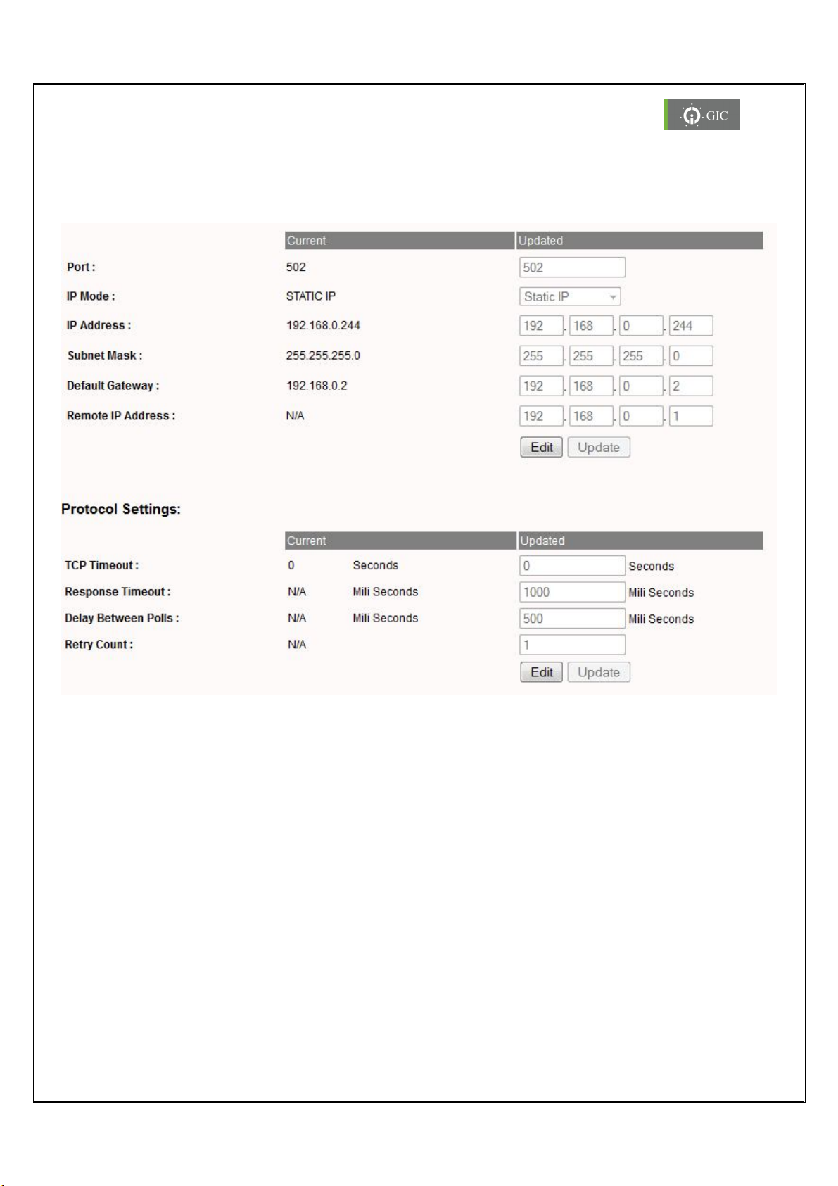
Driver 2 Settings
Driver1 is used to edit the settings of Modbus TCP for both Server / Client.
Click on the Driver2 Settings tab to view or edit the Serial Port settings for Port 2
If port is updated, it should be other than the standard port number.
TCP timeout:
It is the time after which the TCP connection will break if it is in idle state. If this time is not
provided then by default the TCP connection will break in 2 seconds.
Response Timeout:
Timeout is applicable only for Master/Client driver. It is the time for which the device will
wait for the response from external Slave device.
Delay Between Polls:
Delay between polls is applicable only for Master/Client driver. This is the delay between 2
consecutive requests.
Retry Count:
Retry count is applicable only for Master/Client driver. It is the number of times, the
Page 24
Gateway
Page 25
www.gicindia.com
Lynx
'requests' will be sent by the device if it does not receive 'response' from the external slave
device. Valid values can be 1 to 10.
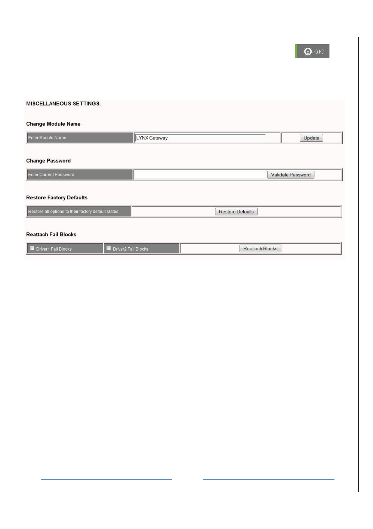
Miscellaneous Settings
Click on Miscellaneous Settings tab for miscellaneous settings. Under Miscellaneous
settings option, user can change Module name, password, restore Factory Default settings
and reattach fail blocks.
Reattach Fail Blocks:
In Background processing data, if Skip on block fail is enabled and any one block fails
then master driver will skip the request for that particular block.
If the Re-attach Fail Blocks option is enabled then the master driver will try to
reattach the failed blocks.
Page 25
Gateway
Page 26
www.gicindia.com
Lynx
Protocol Conversion
MODBUS RTU/ASCII
- MODBUS
TCP
Configuration Software
HTTP Web Server & Windows
based Application Software
to Configure
Port1
: Screw terminals for RS232, RS42
2 and RS485 interface.
Serial Interface Selection
Port1 mode selection using RST switch with MODE LED indication
Serial Line Protection
8 - 15KV ESD for all signals , Opto Isolation 2 KV
LED Indication
s Serial TX and RX, LAN: LINK and Activity, P
ower ON and Error
ESD
IEC 61000
-4-2-
Level II,
Radiated Emission
CISPR 14
-
1 Class A
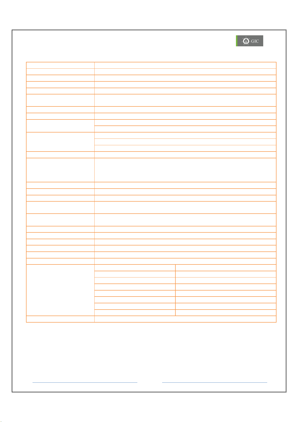
7. Technical Specifications
Power Supply 12 V to 24 V DC (-10% to +25%).
Max Consumption 2 W max
Management HTTP Web Server and Application software
Operation Mode Modbus RTU/ASCII (Slave/Master), Modbus TCP (Client/Server)
Ports as well as Selection of Protocol Driver
Error Detection IP Conflict, Communication Timeout, Idle Connection, IP Search Mode
Number of Serial Ports 2
Serial Interface
Port2: RJ11 for RS232 Interface.
Signals RS232 : RXD, TXD, GND
RS422 :TX+, TX-, RX+, RX-, GND
RS485 : TX+(D+),TX-(D-),GND
Serial Communication
Parameters
LAN Interface RJ45, Ethernet 10/100 Mbps
LAN Isolation 1.5KVrms magnetic Isolation
Network Protocols
Supported
Reset Front Panel recessed key for Serial mode selection & Factory Default
Operating Temperature 0 to + 55oC
Dimensions (W X H X D) 70 X 90 X 58 (mm)
Weight 185 g
Mounting Din Rail/Base
Degree of Protection IP 20
EMI/EMC
Parity : Odd, Even, None
Stop Bits : 1,2
Data Bits : 7,8
Baud Rate : 300 to 115.2Kbps
ARP, TCP, UDP, HTTP, TFTP, BOOTP, ICMP, DHCP, AutoIP, UPnP. Telnet
Settings
Radiated Susceptibility ICE 61000-4-3- Level III,
EFT IEC61000-4-4 Level IV
Surge IEC 61000-4-5 Level III
Conducted Susceptibility ICE 61000-4-6- Level III,
Voltage Dips and Interruptions IEC 61000-4-29,
Conducted Emission CISPR 14-1 Class A
Approvals CE, ROHS
Page 26
Gateway
Page 27
www.gicindia.com
Lynx
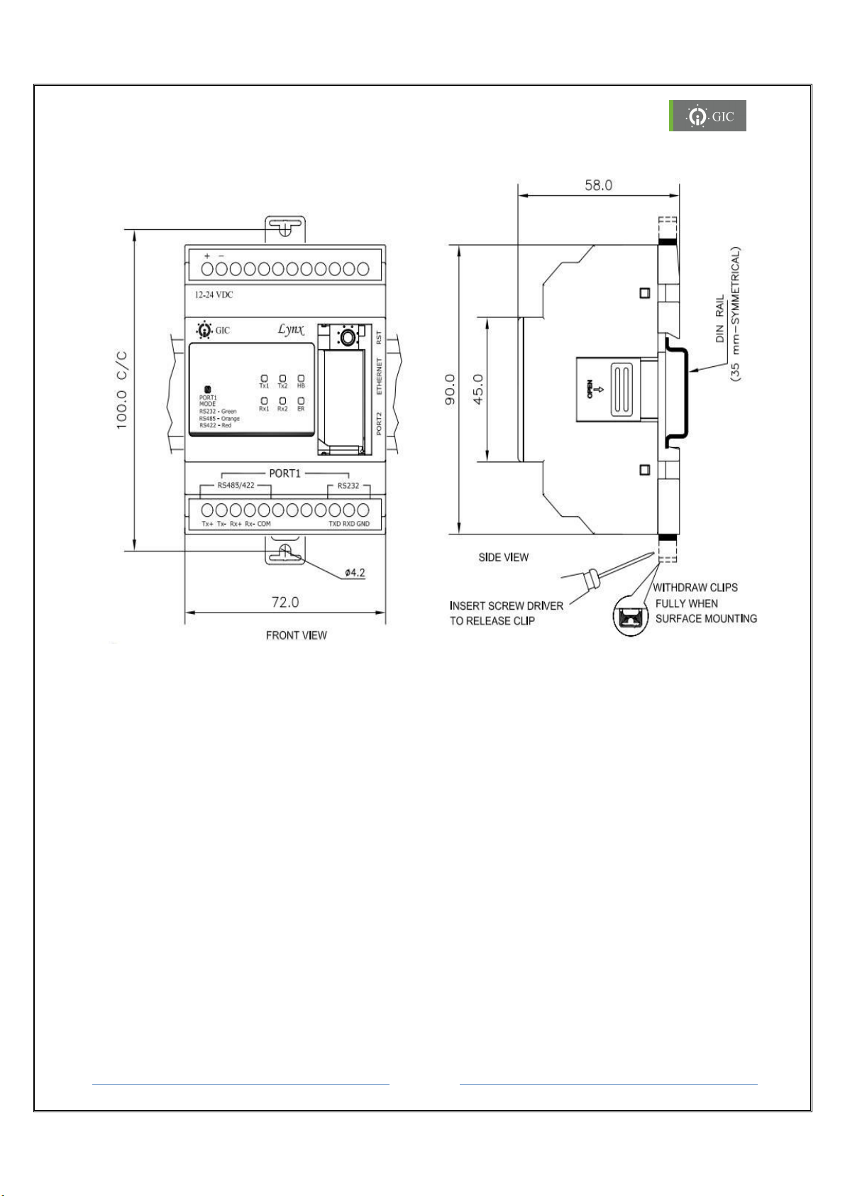
8. Mechanical Dimensions
8.1 Din Rail Mounting
Lynx Gateway can be mounted on a Din Rail. Din Rail locking connectors are provided with
each unit for proper installation. Module must be mounted in an upright position on a
vertical surface or horizontal DIN Rail.
Mounting on Din Rail
1. Pull the Din Rail clips in outward direction from the unit.
2. Mount the unit on the Din Rail and then press the Din Rail Clips to snap fit the device
on the Din Rail.
Removing from Din Rail
1. To remove the unit, pull out the Din Rail clips in outward direction from the unit.
2. Detach the unit from the Din Rail.
Page 27
Gateway
Page 28

www.gicindia.com
Lynx
9. Frequently Asked Questions:
ping 192.168.0.44) is
Problem 1:
Unable to access Web Server through the web browser and the device is also not
present in the Locator utility as well. Ping command (eg:
working and error LED is blinking (500ms ON and 500ms OFF).
Reason:
IP address of the Gateway and other device/PC in the network is same due to
which there is an IP Address conflict and hence error in communication.
Trouble Shooting:
1. To resolve the IP address conflict, change the IP address of any one of the
device's that have the same IP addresses.
2. Disconnect the Gateway from the network and directly connect it to any other PC
using a LAN cable.
3. Locate the Gateway using the locator utility to find the device IP address and then
using the same IP address access web server of device through the web browser.
4. Assign any free static IP address to the device and reconnect it in the network.
Problem 2:
Unable to access Web Server through the web browser and the device cannot in the
Locator utility. Ping command (eg: ping 192.168.0.44) is not working and error LED
is also not blinking.
Reason:
1. Device may be OFF.
2. There may be problem with the Network or network cable.
3. Device may be in Auto IP mode.
4. Device may be out of the Network.
Trouble Shooting:
1. Check device status which is indicated by the Heartbeat LED.
2. If status is healthy then check the network cable
3. Run the device locator utility and check whether the device is present in the network
4. If the device is not present in the network then configure the PC in the AutoIP
address range.
5. Again run the locator utility and check whether the device is present in the network.
6. If device is present, then login to the device web server and change IP address
settings.
7. If device is not present in Auto IP network then the device IP is out of the network or
IP address is corrupted. Reset the device settings to factory default settings using
Page 28
Gateway
Page 29

www.gicindia.com
Lynx
the Reset (RST) key and assign a free IP address to the device from DHCP Server.
8. If DHCP is not present in the network device will go into Auto IP network to set the
static IP to device. Follow Step 1.
Problem 3:
After power on, Error LED blinks for 60 seconds and stops blinking, but cannot locate
the device in Lynx Locator.
Trouble Shooting:
1. IP mode is DHCP mode, check whether the DHCP server is present or not in the
network.
2. If DHCP server is present in the network then contact the system administrator
and check whether DHCP request from this device is configured or not.
Problem 4:
HB LED and ER LED, both are continuously ON.
Reason:
1. Device is not properly configured through Application Software
2. Firmware is not present in the Device
Trouble Shooting:
1. Reset device and observe LED indications. If same status is observed then please
contact: [email protected] or call us at +91-20-3068 0003/39
Problem 5:
A. Error LED is blinking with the rate of 1 sec ON and 10 sec OFF.
Reason:
1. RST key is pressed for more than 12 sec at power ON.
Trouble Shooting:
1. This may be the indication for Reset (RST) key fail. Reset the device and confirm the
Error (ER) LED indications. If the same indication is not observed then it means that
the key was pressed for more that 12 sec at the time of power ON.
2. If the same indications are observed after reset then the Reset (RST) key has failed
and needs to be replaced.
Page 29
Gateway
Page 30

GIC
For Technical Support mail us: [email protected]
| 201221 | 01 |
T-107, M.I.D.C., Bhosari, Pune 411026 (INDIA)
Tel: +91 20 30680003 / 11 / 31 / 39 Fax: +91 20 27122574
Email: [email protected]; [email protected] | www.gicindia.com
Page 31
Page 1
www.gicindia.com
Lynx Gateway
Lynx
Gateway
User Manual
Page 32

Page 2
www.gicindia.com
Lynx Gateway
Table of Contents
1. Introduction 4
1.1. Features 4
1.2. Application 4
2. Knowing the Product 5
2.1. Serial Interface Connection 6
2.2. Ethernet Interface Connection 8
2.3. LED Indications 9
2.4. Reset Switch Functionality 10
2.4.1. Serial Port1 Interface selection 10
2.4.2. Restore Factory Default Settings
3. Working with the Device 12
3.1. MAC ID 12
3.2. IP Address 12
4. Software Installation 14
4.1. Lynx Locator Utility 17
5. Assigning IP Address 19
5.1. Factory Default Settings 19
5.2. Device Configuration Settings 20
6. Settings 21
6.1. Factory Default Settings 21
6.2. Configuring the device
6.2.1 Mapping 22
6.2.2 BPD (Background processing data block) 23
6.3. Device Configuration Settings through web-page 24
7. Technical Specifications 29
8. Mechanical Dimensions 30
8.1. Din Rail Installations 30
9. FAQ’S 31
10. Trouble Shooting 33
Page 33
Page 3
www.gicindia.com
Lynx Gateway
Caution:
Read this manual completely and gather all information on the unit.
For configuring or modifying the IP Address, please contact your network
administrator.
Warning:
Only an expert should change these parameters or settings.
User must definitely know the consequences the changes will have.
This unit must not be operated with removed covers or lids.
Do not attempt to disassemble the unit. There are no user serviceable parts inside.
Do not drop, knock or shake the unit, rough handling above the specification may
cause damage to internal circuit boards.
Do not use harsh chemicals, cleaning solvents or strong detergents to clean the unit.
Do not expose the unit to any kind of liquids. The unit is not water-proof. Keep the
unit within the specified humidity levels.
Do not use or store the unit in dusty, dirty areas.
Page 34

Page 4
www.gicindia.com
Lynx Gateway
1. Introduction
Lynx Gateway is a Serial to Ethernet Protocol Converter providing communication between
Modbus RTU/ASCII Serial devices & Modbus TCP network devices. It supports various
operating modes & can act as Master or Slave. It supports RS 232, RS 422 and RS 485 &
one Ethernet port providing 10/100Mbps through a standard Ethernet connector. Ethernet
side can be configured either as Client or Server.
It intelligently converts the data between Modbus TCP (Ethernet) and Modbus RTU/ASCII
(serial) devices. By enabling Background communication option it is possible to speed up
the data flow at Serial/Ethernet side thus providing seamless integration of Ethernet and
Serial Modbus devices. It can be configured via web-interface or by Lynx gateway utility. It
also provides remote firmware upgrade.
1.1 Features
Supports Modbus RTU/ASCII (Master/Slave) & Modbus TCP (Client/Server) Protocol
Serial interface supports RS-232, RS 422 and RS485 network.
Ethernet interface supports 10/100Mbps with Auto Negotiation
Ethernet Protocols: BOOTP, TFTP, ARP, DHCP, AUTO/IP, ICMP, TELNET, HTTP server
Serial Baud rate supports from 300 bps to 115.2 Kbps.
Static or dynamic IP configuration via DHCP
Integrated HTTP server for device commissioning and configuration via web browser
Isolation between power supply and communication ports
Remote Firmware Upgrade
LED Indications
1.2 Applications
A few of the different types of serial devices supported by the Protocol converter are listed
below:
PLC / HMI / SCADA
Ethernet / Serial based Device monitoring and control system.
Industrial Automation
Data Loggers
Telecommunication Equipment
Security Alarms and Access control systems
Hand Held Instruments
CNC Controllers
Page 35
Page 5
www.gicindia.com
Lynx Gateway
2. Knowing the Product
Power Supply
LED Indications
Serial Port 1
(RS 422/485)
Serial Port 2 (RJ 11)
Ethernet Port
Reset Switch
Serial Port 1
(RS 232)
The Lynx Gateway works on a 12 - 24 VDC supply. There are 2 serial ports (One RJ11 port
for RS 232 & screw terminals for RS 232/422/485) and one Ethernet port provided on the
device for connecting devices for communication. There is a Reset (RST) switch provided on
the device which serves different purposes. There are 7 LEDs indicating the transmission &
reception of data as well as the status of other signals and states.
Page 36
Page 6
www.gicindia.com
Lynx Gateway
2.1. Serial Interface Connections
Signal
Direction
Primary Function
TXD
Out
Transmit Data for RS232
RXD
In
Receive Data for RS232
GND
NA
Ground for RS232
TX+/D+
Out
Differential Transmit Data(+) for RS422/RS485
TX-/D-
Out
Differential Transmit Data(-) for RS422/RS485
RX+
In
Differential Receive Data(+) for RS422
RX-
In
Differential Receive Data(-) for RS422
COM
NA
Ground for RS422/RS485
Pin No
Signal Name
DIR
Primary Function
1
NC - -
2
RXD
In
Receive Data for RS232
3
TXD
Out
Transmit Data for RS232
4
NC - -
5
GND
GND
Ground for RS232
6
NC - -
Tx+ Tx- Rx+ Rx- COM
TXD RXD GND
RS 232
RS 485/422
PORT 1
There are two serial ports provided on the device for communication:
Port 1 & Port 2.
Port 1 (RS232/RS422/RS485):
Port1 is used to connect Master/ Slave devices at serial side. The serial device interface can
be RS-232, RS-485 & RS-422 and the connections are screw terminals. The following
section along with the diagrams describes in detail the practical methods for connecting
devices at the serial end for the RS-232 & RS 422/485 Serial interface.
Serial Interface Signals f or Port 1:
Port 2 (RJ11):
This is an optional port for debugging. RJ11 port is provided for the RS232 connections.
Serial Interface Signals f or Port 2:
Page 37
Page 7
www.gicindia.com
Lynx Gateway
From Lynx S2E
To Device
Signal
Color
Color
Signal
TXD
Brown
Brown
RXD
RXD
Black
Black
TXD
COM
Red
Red
COM
From Lynx S2E
To Device
Signal
Colour
Colour
Signal
TX+
Yellow
Yellow
RX+
TX-
Brown
Brown
RX-
RX+
Red
Red
TX+
RX-
Green
Green
TX-
COM
Black
Black
COM
From Lynx S2E
To Device
Signal
Colour
Colour
Signal
TX+
Red
Red
TX+
TX-
Brown
Brown
TX-
COM
Black
Black
COM
1 5 6
9
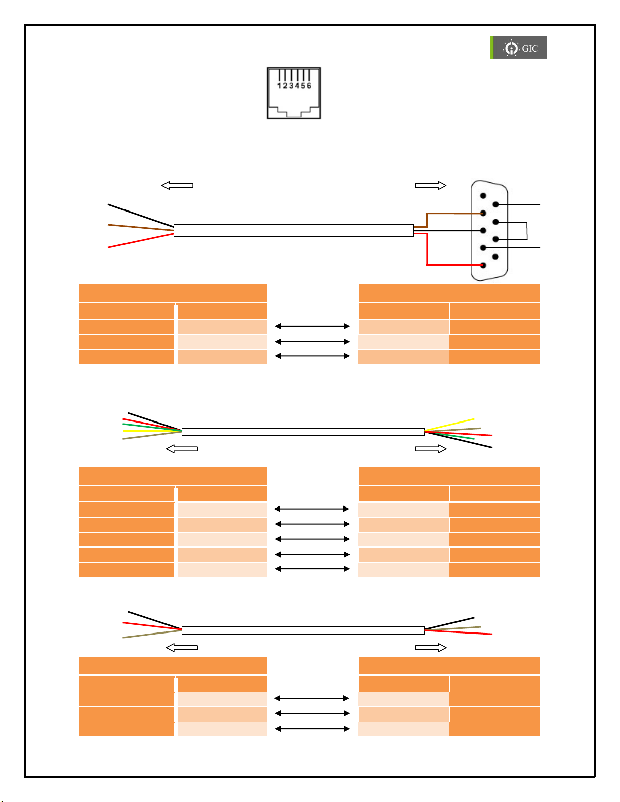
To PC / Device
RS 232 Port
DB9 Female
Pin Out
DSR
DTR
RTS
CTS
1 5 6
9
To Gateway
To Gateway
To Device RS 422 Port
To Gateway
To Device RS 485 Port
RJ 11 Connector
RS232 Cable Diagram:
Note: The above color code is only used for reference
RS422 Cable Diagram:
RS485 Cable Diagram:
Page 38
Page 8
www.gicindia.com
Lynx Gateway
2.2. Ethernet Interface Connections
Signal
Pin
Direction
Primary Function
TX+ 1 Out
Transmit Data +
TX- 2 Out
Transmit Data -
RX+ 3 In
Differential Ethernet Receive Data +
RX- 6 In
Differential Ethernet Receive Data -
1 2 3 4 5 6 7 8 Tx+
Tx-
Rx+
Rx- 1 2 3 4 5 6 7 8
Rx+
Rx-
Tx+
Tx-
PC
Hub
8
7
6 5 4
3
2
1
8
7
6 5 4
3
2
1
Tx+
Tx-
Rx+
Rx-
1
2
3
4 5 6 7 8
Tx+
Tx-
Rx+
Rx-
1
2
3
4 5 6 7 8
Cross Over
PC
PC
8
7
6 5 4
3
2
1
8
7
6 5 4
3
2
1
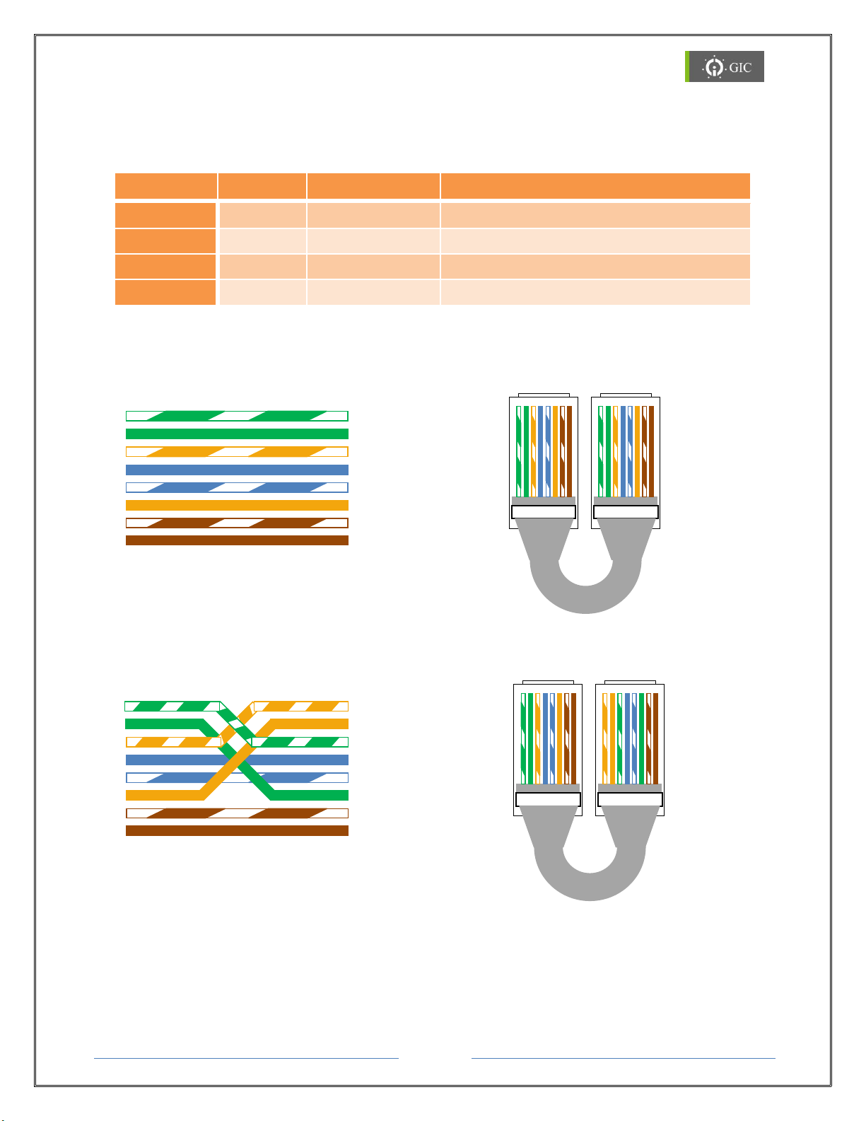
Lynx Gateway supports 10/100Mbps Ethernet through RJ-45 (10BaseT/100BaseTX)
connector. It also supports auto negotiation.
RJ45 Cable Diagram:
Straight Through Cable
Cross Over Cable
Page 39
Page 9
www.gicindia.com
Lynx Gateway
2.3. LED Indications
ERROR LED
HB LED
MODE LED
Serial Port 1 Interface
Selection
RS 232 Interface
Continuous ON
Blinking
Green
RS 422 Interface
Continuous ON
Blinking
Red
RS 485 Interface
Continuous ON
Blinking
Orange
Factory Default Settings
Continuous ON
Blinking
-
Firmware Downloading /
No Firmware
Continuous ON
Continuous ON
NA
LED
Color
Status
Function
HB
Green
Blinking
Healthy Status
ERROR
Red
Blinking
IP Address Search Modes
(100ms ON and 100ms OFF)
IP Address Conflict Error
(500ms ON and 500ms OFF)
TCP idle connection
(100ms ON and 10s OFF)
RST key pressed more than 12sec
(1s ON and 10s OFF)
TX1
Green
Blinking
Serial Port-1 Data Transmit
RX1
Green
Blinking
Serial Port-1 Data Receive
TX2
Green
Blinking
Serial Port-2 Data Transmit
RX2
Green
Blinking
Serial Port-2 Data Receive
Port 1
Mode
Green
Continuous ON
RS232 selected
Red
Continuous ON
RS422 selected
Orange
Continuous ON
RS485 selected
Link
Yellow
Continuous ON
Link (socket connection made)
Activity
Orange
Random Flashing
Activity (network 10/100Mbps)
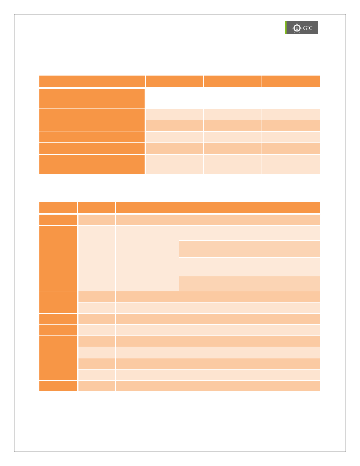
LED Indications for Settings
LED Indications during Run Time
Page 40
Page 10
www.gicindia.com
Lynx Gateway
2.4. RST Switch Functionality
Key Press Interval (T)
Selected Mode
2 sec < T < 8 sec
Serial Interface Selection Mode
8 sec < T < 12 sec
Default Factory Settings Selection
12 sec < T
Reset (RST) Key Fail Error
No. Of times RST key is pressed
LED Color
Interface Mode
1
Red
RS422 Interface mode
2
Orange
RS485 Interface mode
3
Green
RS232 Interface mode
The Reset (RST) key provided on the device is used for the following purposes:
1. Serial Port 1 Interface Selection
2. Restore Factory Default Settings
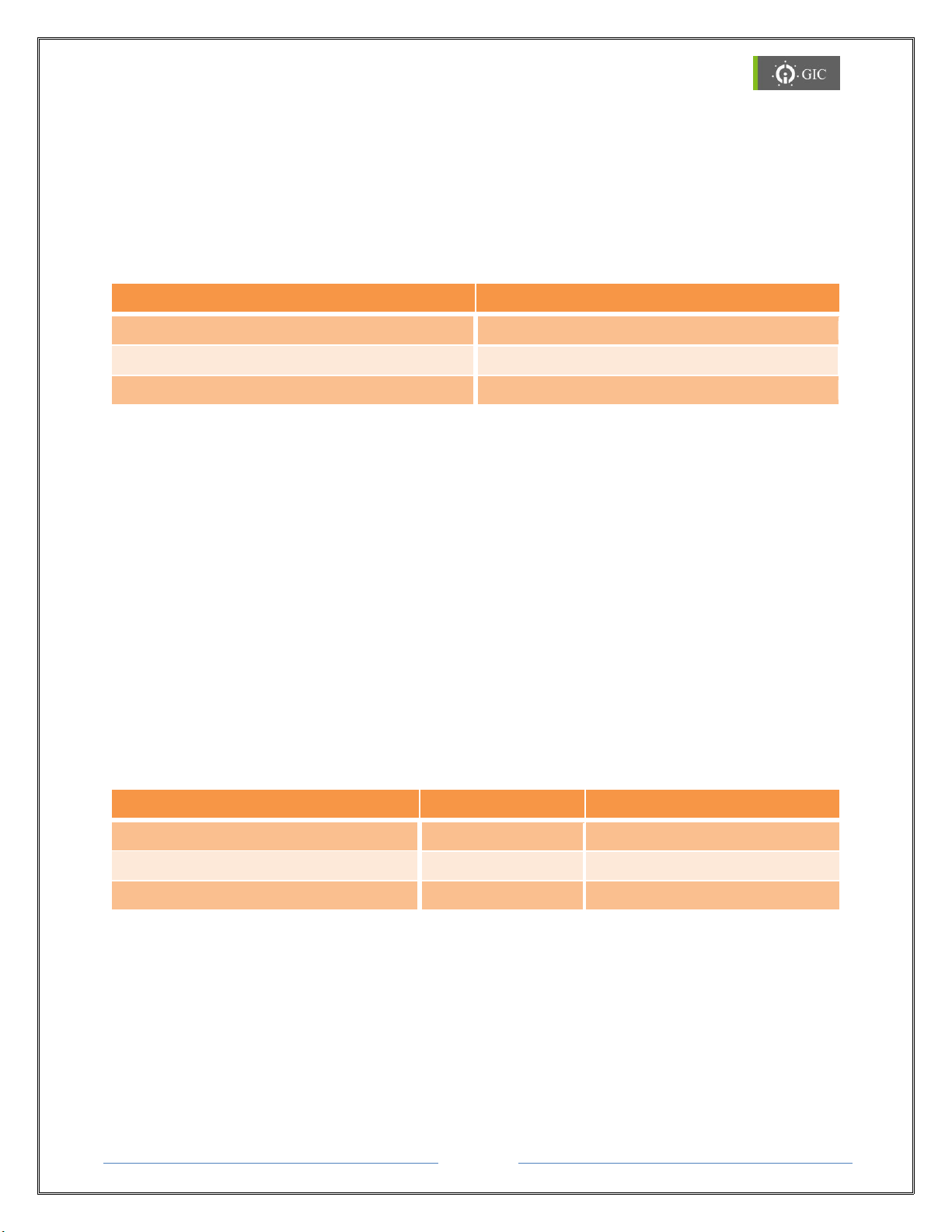
Depending on the time duration for which the RST key is pressed at power on, the particular
mode will be selected
2.4.1 Serial Port1 Interface Selection
Serial Interface Selection Mode is used to select the different Serial Interface modes for
PORT1. The serial interfaces available for port 1 are RS232, RS422 and RS485. Ensure that
the "Port" under Settings under "Driver1 Settings" tab is unlocked. To configure the serial
interface option,
1. Press RST switch & then power ON. Keep the RST switch pressed for 2-8 sec.
2. Error LED glows continuously during Serial Interface Mode selection.
3. Heart Beat (HB) LED starts blinking (150 ms ON & 150 ms OFF) indicating that the
device has entered into Serial Selection Mode.
4. Press and release RST switch to select a particular serial interface option which is
indicated by the MODE LED.
Depending on the number of times the RST key is pressed after the HB LED starts blinking,
the particular mode will be selected.
5. After selecting a particular serial interface, user has to wait for 5 seconds to confirm
the selection which is indicated by fast blinking MODE LED in Orange color. The
device will then run in normal mode which is indicated by the blinking Heart Beat
(HB). (800 ms ON and 800 ms OFF).
6. The MODE LED glows continuously in the selected serial interface color.
Page 41

Page 11
www.gicindia.com
Lynx Gateway
User can lock/unlock the serial selection mode through the web server.
In “Driver1 Settings” page, select “Lock” option to lock/unlock the serial option selected
using RST key.
If Port1 selection is locked and someone is trying to change the serial interface by pressing
RST key, the device will not allow the change and will enter the RUN mode which is
indicated by the blinking MODE LED (for 5 sec) in its programmed serial interface color.
2.4.2 Restore Factory Default Settings
To restore Factory Default Settings of the device,
1. Press RST switch & then power ON. Keep the RST switch pressed for 8-12 sec.
2. Error LED glows continuously during Serial Interface Mode selection.
3. Heart Beat (HB) LED start's blinking (50msec ON & 50msec OFF) indicating that the
device has entered into Factory Default Mode.
4. To confirm the Factory Default settings, again press the Reset (RST) key within the
next 5 seconds.
5. When the settings are restored to factory default the MODE LED starts blinking
(Orange). If the RST key is not pressed within 5 seconds, the device exits the restore
factory default settings mode.
6. After 5sec device runs in normal mode which is indicated by blinking of HB LED for
800msec ON & 800msec OFF. MODE LED glows continuously in green color because
RS232 is the default serial interface mode.
Page 42
Page 12
www.gicindia.com
Lynx Gateway
3. Working with the Device
3.1 MAC (Media Access Control) ID:
A Media Access Control address (MAC address) is a unique identifier assigned to network
interfaces for communications on the physical network segment. MAC addresses are most
often assigned by the manufacturer of a network interface card (NIC) and are stored in its
hardware, the card's read-only memory, or some other firmware mechanism. The MAC
address usually encodes the manufacturer's registered identification number.
Locating the MAC (Media Access Control) ID:
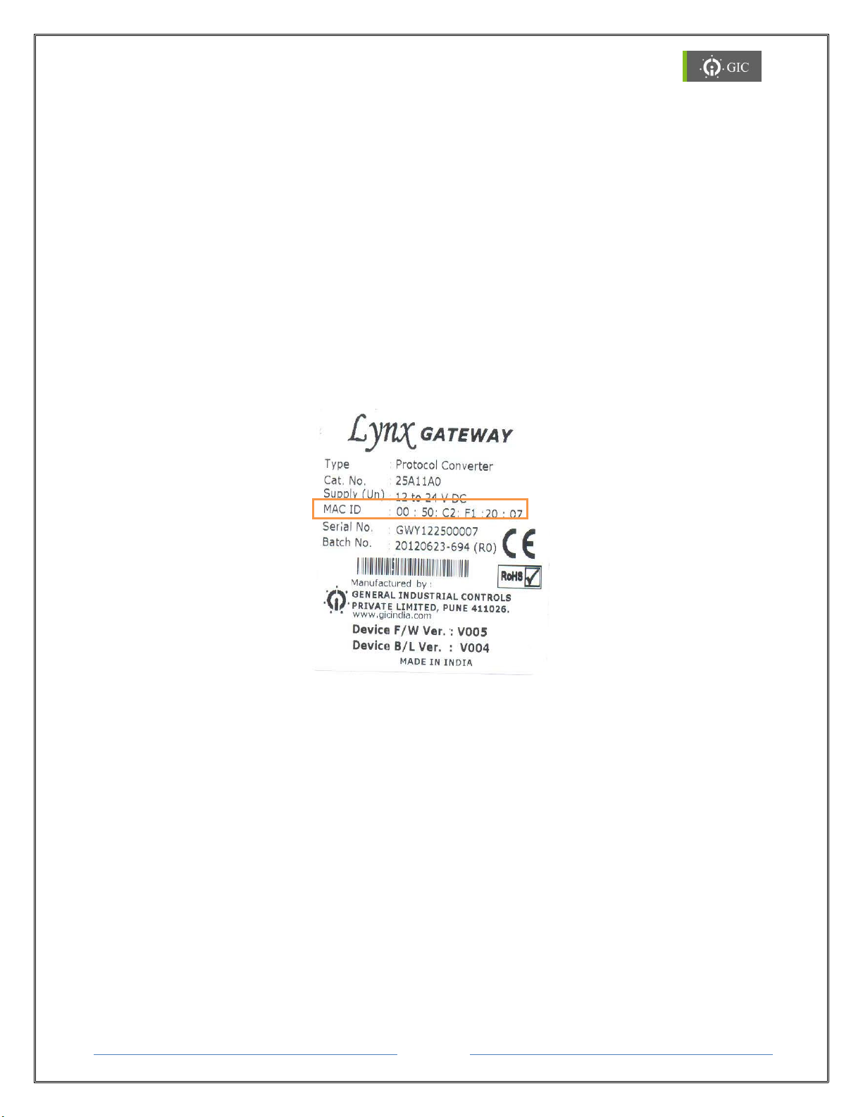
The MAC ID of the Lynx Serial to Ethernet converter is printed on the label attached to the
device. Please refer this MAC ID while assigning IP address to the device through DHCP
server or while configuring the device.
3.2 IP Address
Each TCP/IP node on a network host has a unique IP address. This address provides the
information needed to forward packets on the local network and across multiple networks.
IP addresses are specified as x.x.x.x, where each x is a number from 1 to 254; e.g.,
192.0.1.99. The Device Server must be assigned a unique IP address to use TCP/IP network
functionality.
When the Lynx Gateway Module is powered ON for the first time and connected to an active
network, no IP address in assigned to the device. The device is in Factory Default Mode
which is indicated by continuous blinking of ERROR LED (100ms ON & 100ms OFF).
Device is in DHCP mode
Page 43
Page 13
www.gicindia.com
Lynx Gateway
4. Software Installation
1. Insert the product CD in the CD-ROM drive. The CD will run automatically and the
installation window will be displayed on the screen. If the CD does not run automatically,
open the CD by right clicking on the CD and select ‘open’.
2. Double click on the ‘Setup.msi’ program to begin the installation process.
3. When the installation window appears on the screen click on ‘Next’ to continue
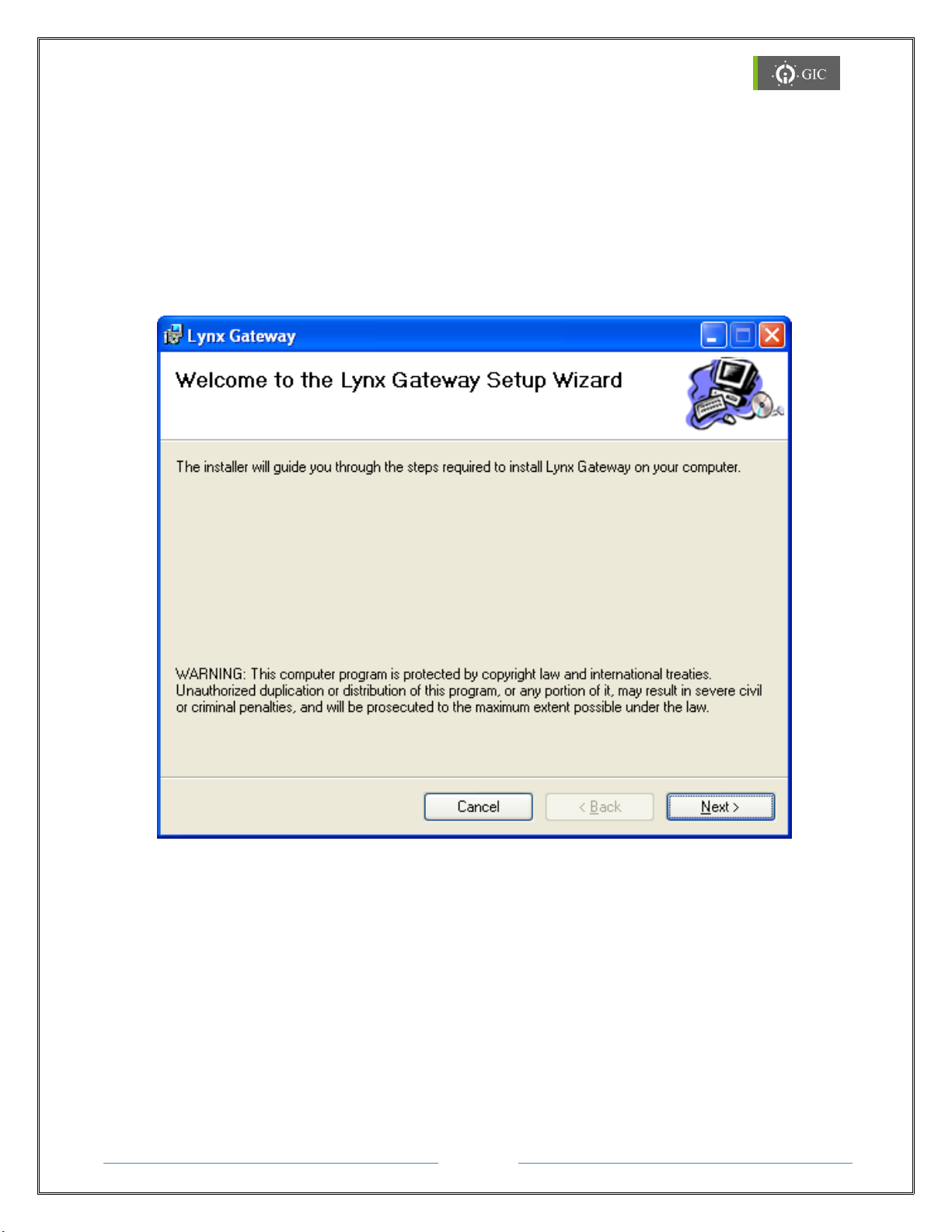
4. A ‘Welcome to the Lynx Gateway Setup Wizard’ window will be displayed on the
screen. Click on ‘Next’ to continue.
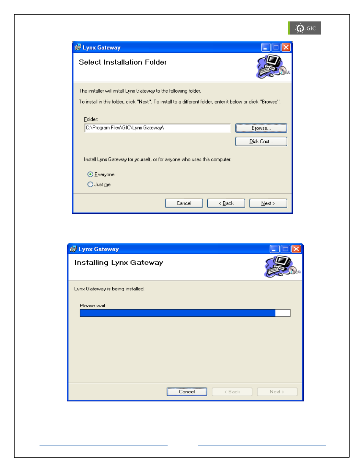
5. When the ‘Select Installation Folder’ window appears on the screen, click on ‘browse’ to
select the folder where the software is to be installed. By default the software will be
installed in (Drive Letter:\Program Files\GIC\Lynx Gateway)
The ‘Disk Cost’ option shows the available drives to install the software along with required
and available space on each drive.
The software may be installed only for the current user or for all users.
Select the correct options and click on Next to continue.
Page 44
Page 14
www.gicindia.com
Lynx Gateway
6. The ‘Installing Lynx Gateway’ Window will appear on the screen indicating the
installation process has started. The procedure will take few seconds to complete.
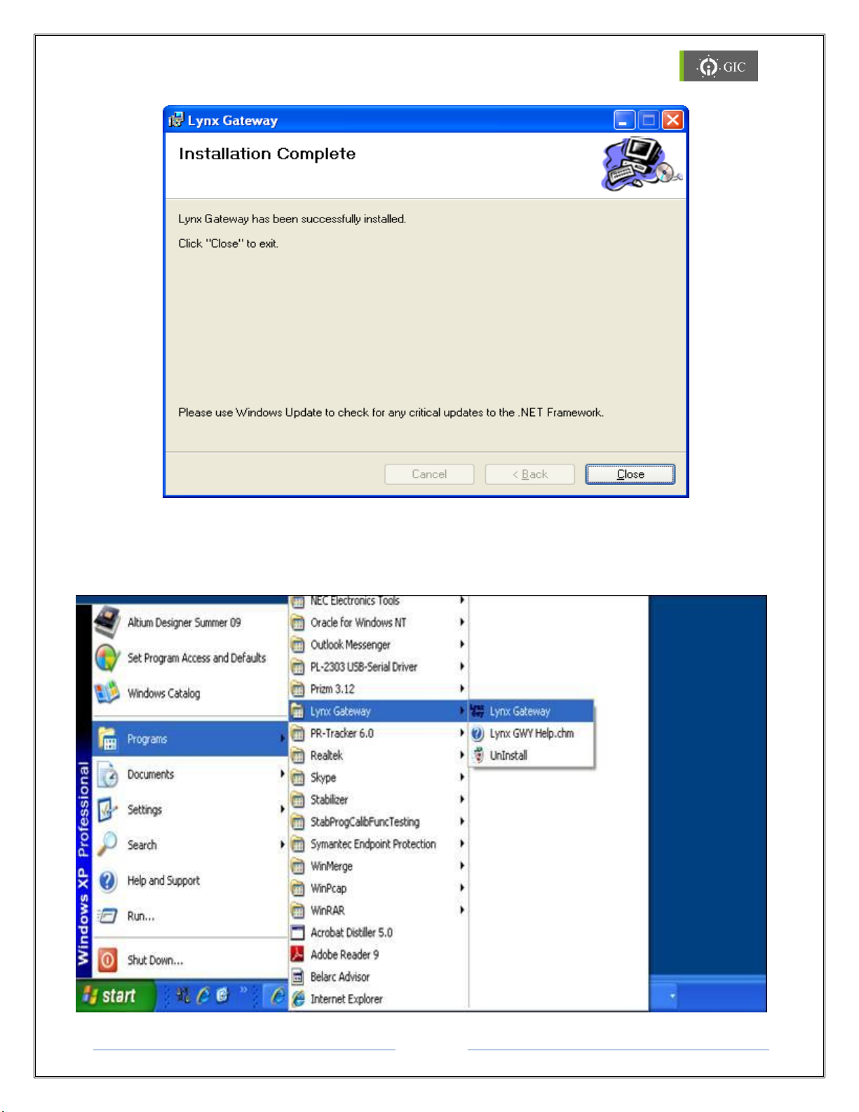
7. When the installation is complete, ‘Installation Complete window’ will appear on the
screen indicating that the Lynx Gateway has successfully installed. Click on ‘Close’ to exit
the wizard.
Page 45
Page 15
www.gicindia.com
Lynx Gateway
8. To launch the Lynx Gateway software:
Double click on the Lynx Gateway Icon on the desktop screen or
Click on Start → Programs → Lynx Gateway → Lynx Gateway
Page 46
Page 16
www.gicindia.com
Lynx Gateway
4.1 Lynx Locator Utility:
Lynx Locator is a utility that locates all the Lynx devices in the network and displays them
in a window along with their IP Address, MAC Address, Remote IP Address and Application
title.
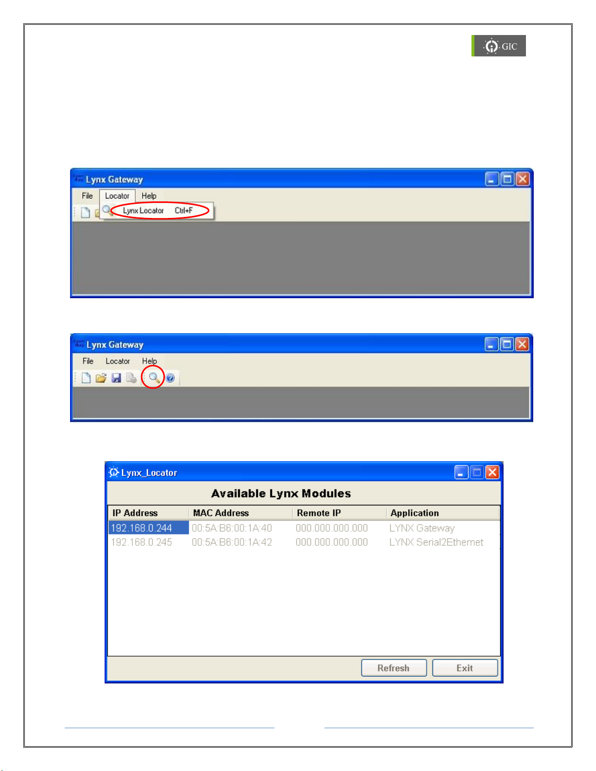
1. To open the utility click on Locator → Lynx Locator(Ctrl+F) in Lynx Gateway
Software OR
2. Click on the short cut placed on the tool bar.
3. The following window with 4 fields is displayed.
Page 47

Page 17
www.gicindia.com
Lynx Gateway
a. IP Address : This field indicates device IP address.
b. MAC Address : This field indicates hardware address of the device.
c. Remote IP : This field indicates IP address of PC to whom Lynx Serial To
Ethernet device has connected.
d. Application Title : This field indicates the name that has been assigned to the
device by the user. If user has not assigned any name to the
device then default name of device will be displayed.
4. Click on Refresh tab to locate the devices that are present in the network.
5. Note the IP address corresponding to the MAC Address & Application Title of the
device.
6. Double clicking on a particular row will open the Web-page of that device.
7. If the device is Factory Default Mode and can't be located in the utility, then change
the IP address of the PC to AutoIP range 169.254.0.1 to 169.254.255.254 & then try
to locate the device.
8. If the device contains IP address which is not in the same network as the PC, device
won't be located in the utility. In such case Restore Factory Default settings of the
device using the RST switch as explained in 2.4.2.
9. Exit tab quits the Lynx Locator utility.
Note:
For upgrading Firmware and configuring Driver settings, refer the “Help file” in
the software. Initially Driver1 is configured as Modbus RTU Master and Driver2 as
Modbus TCP server in transparent mode of communication.
Page 48

Page 18
www.gicindia.com
Lynx Gateway
5. Assigning IP Address
IP address can be assigned to the device through web-server in 3 different ways.
Note: The device is configured for DCHP mode in factory default settings.
1. DHCP/Auto IP mode
In DHCP/Auto IP mode, IP address is assigned to the device if DHCP server is present in
the network. If DHCP server is not present in the network, IP address will be assigned
from the Auto/IP range. In that case follow the procedure as specified in Auto IP mode.
2. Auto IP mode
In Auto IP mode, IP address is assigned to the device by the network from the AutoIP
range 169.254.0.1 to 169.254.255.254. Change the IP address of the PC from the
existing one to the one from the AutoIP range with Sub-net mask 255.255.000.000 and
then locate the device in the locator utility. (Refer 4.1.2)
3. Static IP mode
In static IP mode, you should assign a free IP address to the device and the
corresponding sub-net mask. Care should be taken that the IP address assigned to the
device is in same network as the PC. Also the sub-net mask of the device and PC should
be same.
5.1. If DHCP server is present in the network:
1. A Free IP address in the network is assigned to the device.
2. Error LED indication will stop blinking.
3. Locate the device in Lynx Locator Utility as shown in section 3.2 and observe the
assigned IP address.
4. Enter this IP Address in the address bar of web browser to change the configuration
parameters.
5.2. If DHCP server is not available in the network:
1. If the device is powered ON and DHCP server is not present in the network, then
after 60 seconds the device enters in to Auto IP mode.
2. An IP address from the range 169.254.0.1 to 169.254.255.254 is assigned to the
device
3. Locate the device in the network by using the Lynx Locator Utility.
4. If the device can't be located in Lynx Locator Utility, change the IP Address of the
computer from the existing one to the one from the AutoIP range 169.254.0.1 to
169.254.255.254 with sub-net mask 255.255.0.0
Note:
Device and PC should be in the same Ethernet Network to be located in
locator utility.
Note down the initial IP Address & sub-net mask of PC before changing.
Page 49

Page 19
www.gicindia.com
Lynx Gateway
5. Now, locate the device in the network using the Lynx Locator utility
6. Enter the IP address of the device displayed in the Lynx Locator utility in the address
bar of the web browser.
7. Now change the IP address to static and configuration settings of the device if
required.
8. Revert back IP address settings of PC, and locate device in Lynx Locator utility with
new assigned IP address.
9. If the IP address assigned to the device and PC are in different networks, device will
not be located in Lynx Locator Utility, press Reset (RST) to restore Factory Default
Settings as shown in section 2.4.2.
Page 50
Page 20
www.gicindia.com
Lynx Gateway
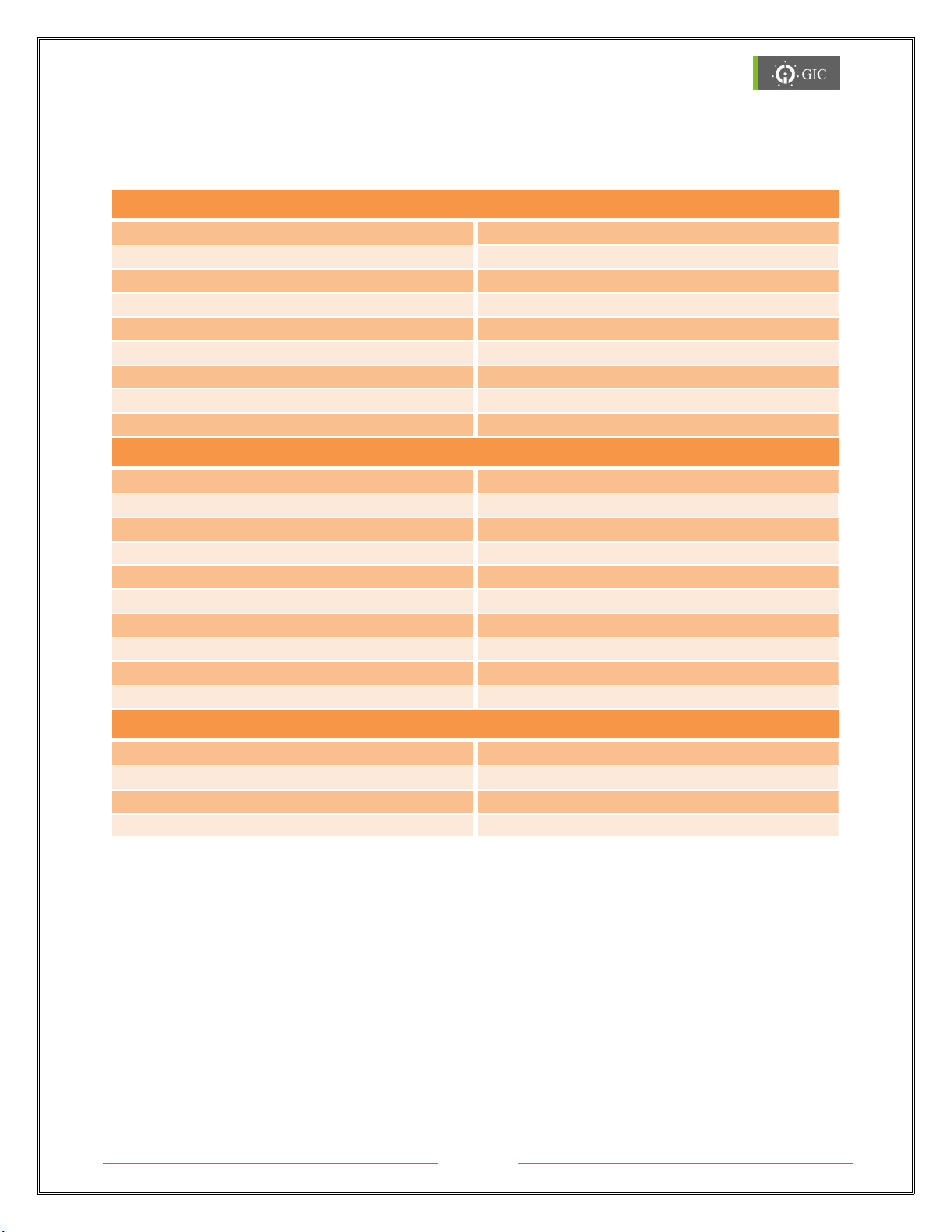
6. Settings
Driver 1 Settings
Port
RS-232
Baud Rate
9600
Data Size
8
Parity
None
Stop Bits
1
Response Timeout
1000msec
Delay between polls
500msec
Retry count
1
Slave ID
1
Driver 2 Settings
Port
502
IP mode
DHCP
IP address
Address assigned by DHCP Server
Sub-net mask
Address assigned by DHCP Server
Default Gateway
Address assigned by DHCP Server
Remote IP
0.0.0.0
TCP Timeout
0msec
Response Timeout
1000msec
Delay between Polls
500msec
Retry Count
1
Miscellaneous Settings
Module Name
LYNX Gateway
Password
gateway
Communication Mode
TRANSPERENT
Firmware Download through Software
Disable
6.1 Factory Default Settings:
Page 51

Page 21
www.gicindia.com
Lynx Gateway
6.2 Configuring the Device:
Lyxn Protocol Converter has got two drivers, Serial Driver and TCP/IP driver to be
configured. Serial Driver can be configured either as RTU/ASCII in Master/Slave mode.
TCP/IP Driver can be configured as Server/Client. Device can operate in any one of the two
communication modes.
Transparent Mode:
Transparent mode is supported only in Master/Slave configuration. In this mode Mapping
and Background Process Data block (BPD) is not enabled. In Factory Default Settings,
communication mode is transparent.
Mapping Mode:
In mapping Mode Mapping and Back Background Process Data block (BPD) is enabled. It is
supported by both, Master/Slave configuration and Master/ Master configuration. For
mapping and BPD, refer Mapping and Back Background Process Data block (BPD).
Page 52
Page 22
www.gicindia.com
Lynx Gateway
6.2.1 Mapping:
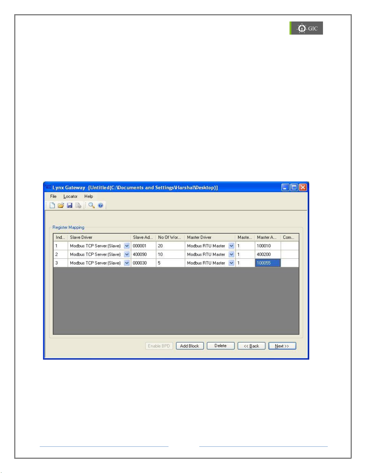
Mapping is used to map the different register sets of various or same protocols which are
configured in either ports of Gateway.
Suppose a gateway is configured as Protocol-X on port1 with A sets of registers and
Protocol-Y on port2 with B sets of registers. Now user want to map the data of A register set
of one protocol to B register set of another protocol. Following is the mapping table user can
enter:
1. Port1- Register-A: 1 to 20 MAPPED WITH Port2 – Register-B: 10 to 30
2. Port1- Register-A: 90 to 100 MAPPED WITH Port2 – Register-B: 200 to 210
3. Port1- Register-A: 30 to 35 MAPPED WITH Port2 – Register-B: 55 to 60
To implement the above shown table in Gateway, the mapping scheme is implemented,
through which user can map the different register sets of different/same protocols on either
communication ports. In this way the data will be shared from one protocol to other, which
serves the function of protocol converter.
Page 53
Page 23
www.gicindia.com
Lynx Gateway
6.2.2 BPD (Background Process Data Block):
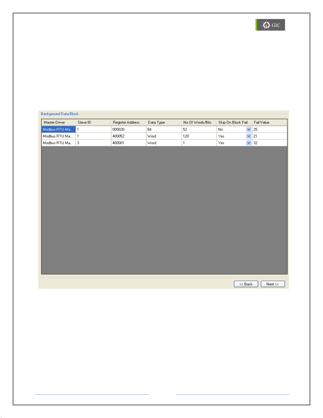
Internal Data Base is a concept wherein the data for the registers mapped in the project is
fetched internally (or to say in the background) and the values are maintained internally by
the Master Drivers.
If background communication is enabled, master driver will use inputs from internal
database (IDB) and continuously start-fetching data for defined registers in IDB,
independent to other side driver. This data is stored in internal data memory. When request
comes from other end external master for mapped registers in gateway projects then data
is given from internal memory so time for data fetching from slave device is minimized.
Page 54
Page 24
www.gicindia.com
Lynx Gateway
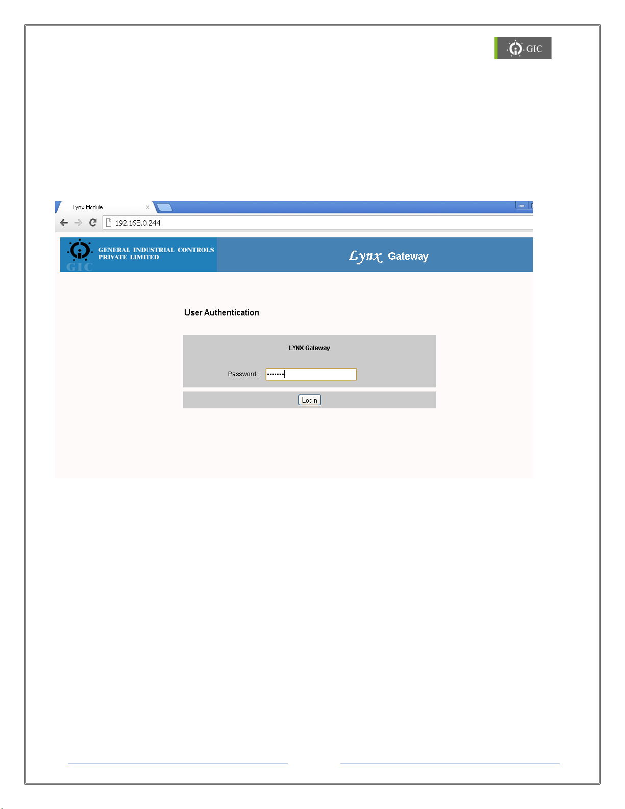
6.3 Device Configuration Settings through web-page:
The device current configuration settings can be viewed & edited by accessing the web
server page
1. To access the web server for device type “http://” command followed by IP address
of the device whose configuration settings are to be viewed or edited.
e.g. - http://192.168.0.244
2. The User Authentication page is displayed for authentication.
3. Enter the valid password to access the web server and click on “Login” button.
4. If password is valid then the Home page is displayed or else the same page is
displayed.
Note: Default Password is “gateway”
Page 55
Page 25
www.gicindia.com
Lynx Gateway
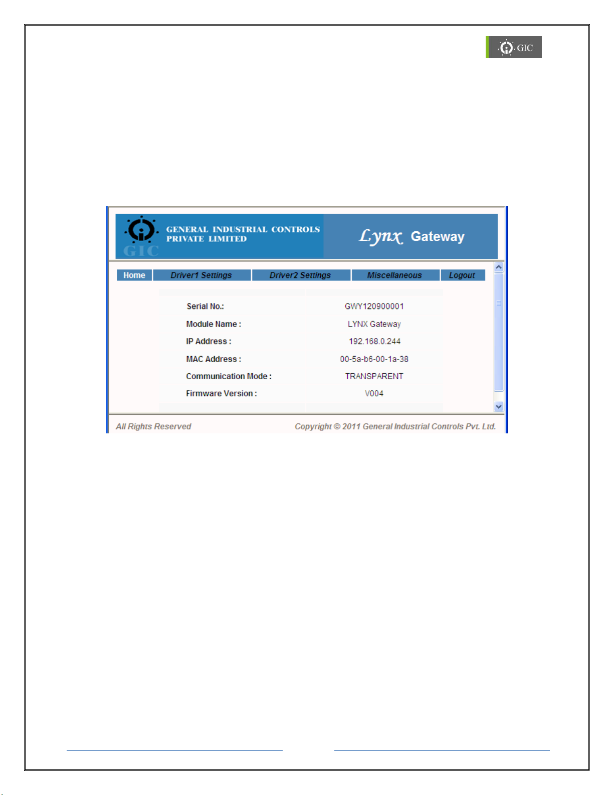
Home Page:
Home page displays following device information:
1. Device Serial No
2. Module Name
3. IP Address
4. MAC Address
5. Communication Mode
6. Firmware Version.
Page 56
Page 26
www.gicindia.com
Lynx Gateway
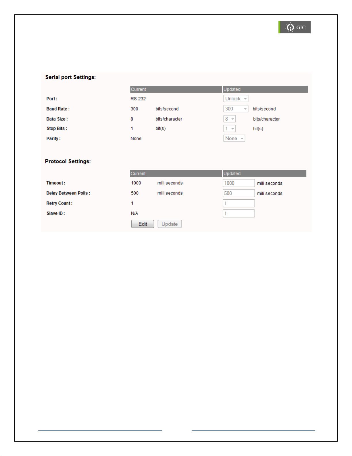
Driver 1 Settings (Serial Port Settings)
Driver1 is used to edit the settings of Modbus RTU/ASCII for both Master/Slave.
Click on the Driver1 Settings tab to view or edit the settings for serial Port 1.
Baud Rate, Data Size, Stop Bits, Parity are the parameters to be updated from the serial
side
Timeout:
Timeout is applicable only for Master/Client driver. It is the time for which the device will
wait for the response from external Slave device.
Delay between Polls:
Delay between polls is applicable only for Master/Client driver. This is the delay between 2
consecutive requests.
Retry Count:
Retry count is applicable only for Master/Client driver. It is the number of times, the
'requests' will be sent by the device if it does not receive 'response' from the external slave
device. Valid values can be 1 to 10.
Slave ID:
Slave ID is applicable only for Slave/Server driver.
Page 57
Page 27
www.gicindia.com
Lynx Gateway
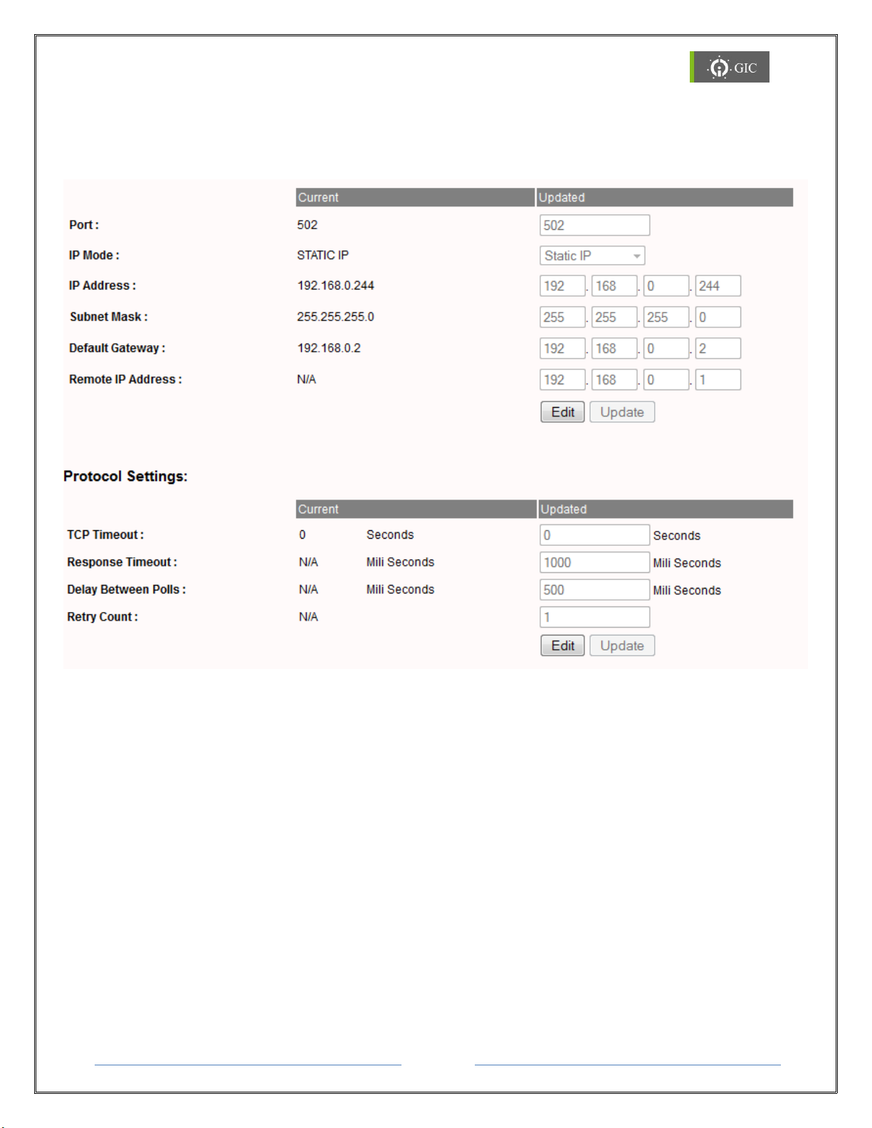
Driver 2 Settings
Driver1 is used to edit the settings of Modbus TCP for both Server / Client.
Click on the Driver2 Settings tab to view or edit the Serial Port settings for Port 2
If port is updated, it should be other than the standard port number.
TCP timeout:
It is the time after which the TCP connection will break if it is in idle state. If this time is not
provided then by default the TCP connection will break in 2 seconds.
Response Timeout:
Timeout is applicable only for Master/Client driver. It is the time for which the device will
wait for the response from external Slave device.
Delay between Polls:
Delay between polls is applicable only for Master/Client driver. This is the delay between 2
consecutive requests.
Retry Count:
Retry count is applicable only for Master/Client driver. It is the number of times, the
Page 58
Page 28
www.gicindia.com
Lynx Gateway
'requests' will be sent by the device if it does not receive 'response' from the external slave
device. Valid values can be 1 to 10.
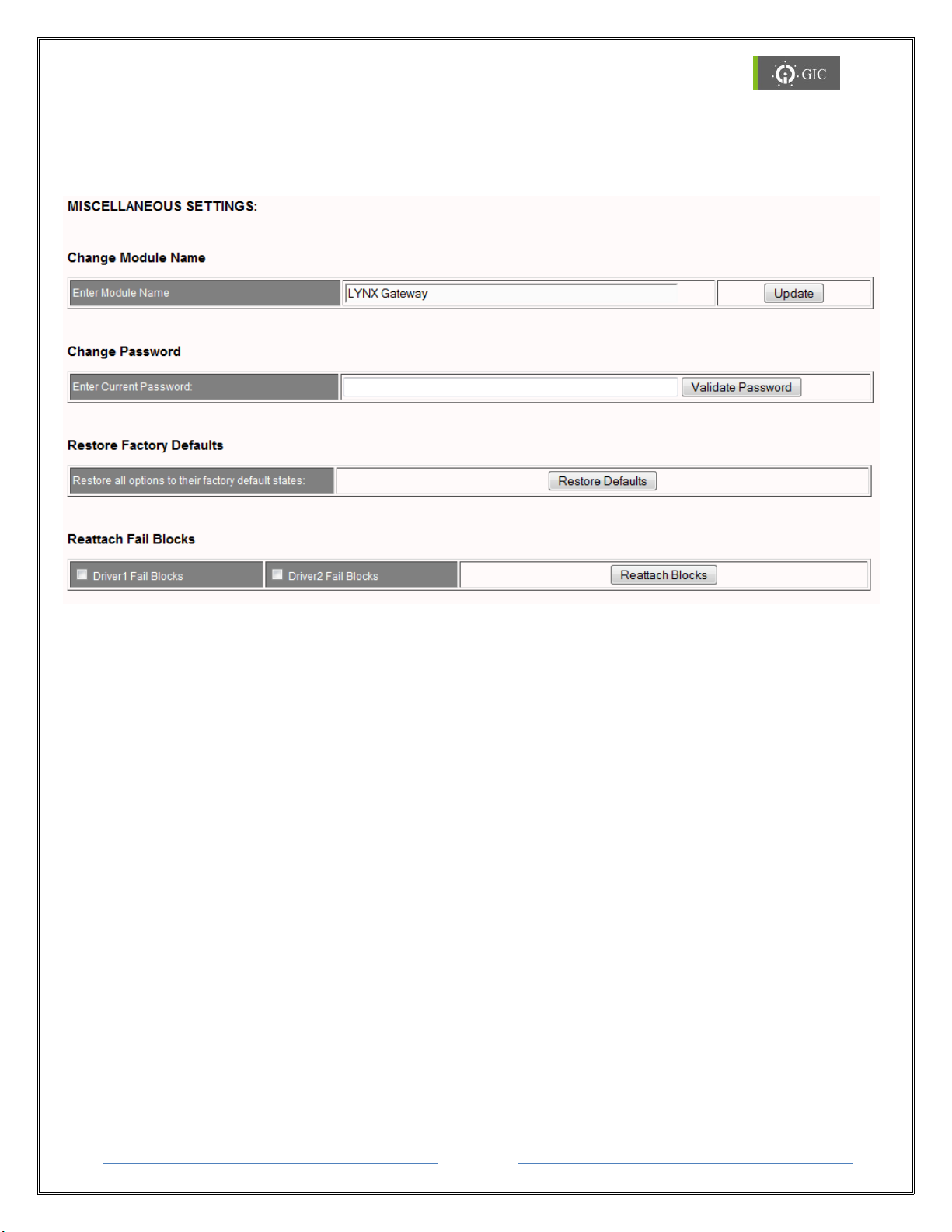
Miscellaneous Settings
Click on Miscellaneous Settings tab for miscellaneous settings. Under Miscellaneous
settings option, user can change Module name, password, restore Factory Default settings
and reattach fail blocks.
Reattach Fail Blocks:
In Background processing data, if Skip on block fail is enabled and any one block fails
then master driver will skip the request for that particular block.
If the Re-attach Fail Blocks option is enabled then the master driver will try to
reattach the failed blocks.
Page 59
Page 29
www.gicindia.com
Lynx Gateway
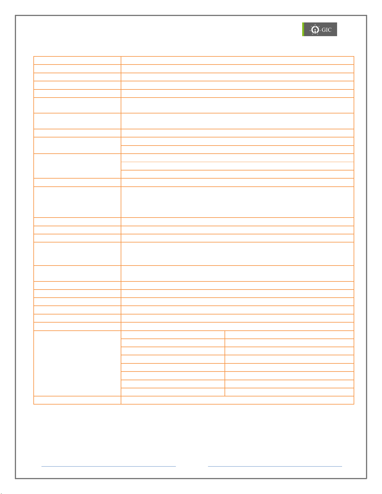
7. Technical Specifications
Power Supply
12 V to 24 V DC (-10% to +25%).
Max Consumption
2 W max
Management
HTTP Web Server and Application software
Protocol Conversion
MODBUS RTU/ASCII - MODBUS TCP
Operation Mode
Modbus RTU/ASCII (Slave/Master), Modbus TCP (Client/Server)
Configuration Software
HTTP Web Server & Windows based Application Software to Configure
Ports as well as Selection of Protocol Driver
Error Detection
IP Conflict, Communication Timeout, TCP Idle Connection, IP Search
Mode
Number of Serial Ports
2
Serial Interface
Port1: Screw terminals for RS232, RS422 and RS485 interface.
Port2: RJ11 for RS232 Interface.
Signals
RS232 : RXD, TXD, GND
RS422 :TX+, TX-, RX+, RX-, GND
RS485 : TX+(D+),TX-(D-),GND
Serial Interface Selection
Port1 mode selection using RST switch with MODE LED indication
Serial Communication
Parameters
Parity : Odd, Even, None
Stop Bits : 1,2
Data Bits : 7,8
Baud Rate : 300 to 115.2Kbps
Serial Line Protection
8 - 15KV ESD for all signals , Opto Isolation 2 KV
LAN Interface
RJ45, Ethernet 10/100 Mbps
LAN Isolation
1.5KVrms magnetic Isolation
Network Protocols
Supported
Protocols for Communication : TCP/IP, Telnet(RFC2217)
Std. Protocols used :ARP, HTTP, ICMP, DHCP, AutoIP, BOOTP, UPnP
Protocols used Internally : UDP, TFTP
Reset
Front Panel recessed key for Serial mode selection & Factory Default
Settings
LED Indications
Serial TX and RX, LAN: LINK and Activity, Power ON and Error
Operating Temperature
0 to + 55oC
Dimensions (W X H X D)
70 X 90 X 58 (mm)
Weight
185 g
Mounting
Din Rail/Base
Degree of Protection
IP 20
EMI/EMC
ESD
IEC 61000-4-2-Level II,
Radiated Susceptibility
ICE 61000-4-3- Level III,
EFT
IEC61000-4-4 Level IV
Surge
IEC 61000-4-5 Level III
Conducted Susceptibility
ICE 61000-4-6- Level III,
Voltage Dips and Interruptions
IEC 61000-4-29,
Conducted Emission
CISPR 14-1 Class A
Radiated Emission
CISPR 14-1 Class A
Approvals
CE, ROHS
Page 60
Page 30
www.gicindia.com
Lynx Gateway
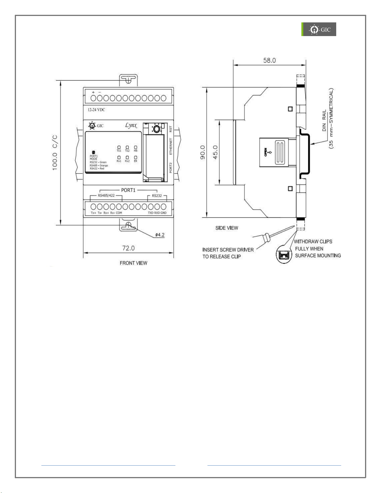
8. Mechanical Dimensions
8.1 Din Rail Mounting
Lynx Gateway can be mounted on a Din Rail. Din Rail locking connectors are provided with
each unit for proper installation. Module must be mounted in an upright position on a
vertical surface or horizontal DIN Rail.
Mounting on Din Rail
1. Pull the Din Rail clips in outward direction from the unit.
2. Mount the unit on the Din Rail and then press the Din Rail Clips to snap fit the device
on the Din Rail.
Removing from Din Rail
1. To remove the unit, pull out the Din Rail clips in outward direction from the unit.
2. Detach the unit from the Din Rail.
Page 61

Page 31
www.gicindia.com
Lynx Gateway
9. Frequently Asked Questions (FAQ’s)
Q. How to know how many devices are connected in the network?
A. Run the Locator Utility provided along with the Lynx Gateway Software. Locator will
display all the devices connected in the network along with their MAC ID and IP address.
Q. How to find the IP address of the device?
A. Run the Locator Utility provided along with the Lynx Gateway Software. It will display all
the devices connected in the network. Locate the IP address corresponding to the MAC ID of
your device. If you cannot locate the device in Locator utility, refer to section 4.1
Q. How to change the IP address of the Lynx Gateway module?
A. Access the web-page with the already assigned IP address to the device.
Click on Driver2 settings tab.
Edit the IP address to DHCP/AutoIP or Static or AutoIP according to the requirement.
Update the changes.
Q. How to change the Serial Interface of the device?
A. Serial Interface can only be selected for Port1.Before changing the serial Interface,
ensure that the "Port" under serial port settings is unlocked under Driver1 settings page on
web-page. To change the Serial Interface of the device, refer to section 2.4.1.
Q. How to change the Serial Parameters of the device?
A. Access the web-page with the assigned IP address to the device.
Click on Driver1 settings tab.
Edit the Serial parameters like Baud-rate, Data-size, Stop-bits and Parity and update
the changes.
Q. How to Restore Factory Default Settings of the device?
A. Factory Default Settings can be restored by two methods:
1) Restore Factory Default Settings through Web-page:
Access the web-page with the assigned IP address to the device.
Click on Miscellaneous Settings tab.
Click on "Restore Defaults"
2) Restore Factory Default Settings through Reset key:
Refer to section 2.4.2.
Q. What are the requirements before implementing "mapping"?
A. Before implementing Mapping, user should know following things:
1) Device ID and Address Map of the parameters of the devices to be interfaced.
Page 62

Page 32
www.gicindia.com
Lynx Gateway
2) Total number of words/bytes to be mapped.
3) If Background Process Data Block is enabled, fail values should be known.
For more information, refer to "Mapping and BPD" section in help file.
Q. How to implement mapping in Lynx Gateway software?
A. To implement mapping user should know the Slave addresses and Master addresses of
the devices to be interfaced. Use these addresses in the mapping register and then
configure the Lynx Gateway module.
Q. IP address is changed in "MAC and IP address information section" and device
is configured, but device is not working with the assigned IP address.
A. IP address displayed in "MAC and IP address information "section is used only for the
firmware download purpose. It does not assign the IP address to the device.
To change the IP address of the device, follow following steps:
1) In Lynx Gateway, IP address can be changed by editing the IP address under Driver2
Settings in Lynx Gateway software or through web-page.
2) In Serial-to-Ethernet converter, IP address can be changed through web-page by
editing the IP address under Miscellaneous Settings tab
Q. Device is configured with, but cannot access the web-page.
A. 1) Check the IP address of the device using Locator Utility.
2) Check if IP address of PC and the device are in same network.
3) If web-page is not accessible due to password, try it with default password i .e.
"gateway".
Q. While configuring the device, window displays, "Firmware Code Error".
A. Your device is configured with "Lynx Gateway" and you are trying to configure "Serial-toEthernet Converter" or vice-versa.
This is not allowed.
Page 63

Page 33
www.gicindia.com
Lynx Gateway
10. Trouble Shooting:
Problem 1:
Unable to access Web Server through the web browser and the device is also not
present in the Locator utility as well. Ping command (eg: ping 192.168.0.44) is
working and error LED is blinking (500ms ON and 500ms OFF).
Reason:
IP address of the Gateway and other device/PC in the network is same due to
which there is an IP Address conflict and hence error in communication.
Trouble Shooting:
1. To resolve the IP address conflict, change the IP address of any one of the
device's that have the same IP addresses.
2. Disconnect the Gateway from the network and directly connect it to any other PC
using a LAN cable.
3. Locate the Gateway using the locator utility to find the device IP address and then
using the same IP address access web server of device through the web browser.
4. Assign any free static IP address to the device and reconnect it in the network.
Problem 2:
Unable to access Web Server through the web browser and the device cannot in the
Locator utility. Ping command (eg: ping 192.168.0.44) is not working and error LED
is also not blinking.
Reason:
1. Device may be OFF.
2. There may be problem with the Network or network cable.
3. Device may be in Auto IP mode.
4. Device may be out of the Network.
Trouble Shooting:
1. Check device status which is indicated by the Heartbeat LED.
2. If status is healthy then check the network cable
3. Run the device locator utility and check whether the device is present in the network
4. If the device is not present in the network then configure the PC in the AutoIP
address range.
5. Again run the locator utility and check whether the device is present in the network.
6. If device is present, then login to the device web server and change IP address
settings.
7. If device is not present in Auto IP network then the device IP is out of the network or
IP address is corrupted. Reset the device settings to factory default settings using
Page 64

Page 34
www.gicindia.com
Lynx Gateway
the Reset (RST) key and assign a free IP address to the device from DHCP Server.
8. If DHCP is not present in the network device will go into Auto IP network to set the
static IP to device. Follow Step 1.
Problem 3:
After power on, Error LED blinks for 60 seconds and stops blinking, but cannot locate
the device in Lynx Locator.
Trouble Shooting:
1. IP mode is DHCP mode, check whether the DHCP server is present or not in the
network.
2. If DHCP server is present in the network then contact the system administrator
and check whether DHCP request from this device is configured or not.
Problem 4:
HB LED and ER LED, both are continuously ON.
Reason:
1. Device is not properly configured through Application Software
2. Firmware is not present in the Device
Trouble Shooting:
1. Reset device and observe LED indications. If same status is observed then please
contact: [email protected] or call us at +91-20-3068 0003/39
Problem 5:
A. Error LED is blinking with the rate of 1 sec ON and 10 sec OFF.
Reason:
1. RST key is pressed for more than 12 sec at power ON.
Trouble Shooting:
1. This may be the indication for Reset (RST) key fail. Reset the device and confirm the
Error (ER) LED indications. If the same indication is not observed then it means that
the key was pressed for more that 12 sec at the time of power ON.
2. If the same indications are observed after reset then the Reset (RST) key has failed
and needs to be replaced.
 Loading...