

USE AND MAINTENANCE MANUAL
DECLARATION OF QUALITY
DECLARATION OF WARRANTY
DECLARATION OF PERFORMANCE DoP
LINE MEDITERRANEA
MODEL
MEDISOLAFLY R
ISLAND, FRONTAL LEANING VERSION, LATERAL LEANING VERSION
SINGLE-MODULE, PLURI-MODULE, FLY FAbRIc cOVER
ENG
MUT 088
Rev. 1
01/03/2017
Gibus S.p.A. Via Luigi Einaudi, 35 35030 Saccolongo (PD) - ITALY www.gibus.it - gibus@gibus.it

Page 3 of 56
USE AND MAINTENANCE MANUAL
Code MUT 088
Rev. 1
WARNING: CAREFULLY READ ALL WARNINGS AND INSTRUCTIONS IN THIS
MANUAL AND IN THE USE AND MAINTENANCE MANUAL BEFORE CARRYING
OUT ANY OPERATION WITH THE AWNING.
READ IN PARTICULAR THE CHAPTER ON SAFETY.
Dear Customer,
thank you for choosing an awning by "GIBUS", we are pleased to deliver this manual in order to
help you to use the product in the best possible way.
Please read carefully the recommendations described in the following pages and keep the manual
at hand for the Gibus specialist who will be responsible for management and maintenance of
the awning.
Gibus S.p.A.
via Luigi Einaudi, 35
35030 Saccolongo (PD) - ITALY
www.gibus.it - gibus@gibus.it
www.gibus.com

Page 4 of 56
USE AND MAINTENANCE MANUAL
Code MUT 088
Rev. 1
Gibus S.p.A. reserves all rights to this manual, including the right, at any time, to make any
necessary changes aimed at improving its products and the manual itself without prior notice.
The reproduction, even partial, of this manual is strictly forbidden without the permission of
Gibus S.p.A.
www.gibus.com
Page 5 of 56
USE AND MAINTENANCE MANUAL
Code MUT 088
Rev. 1
1 INTRODUCTION 7
1.1 Getting started 7
1.2 Warnings for use 7
1.3 Regulations and self-certification documentation 8
1.4 Liability 9
1.5 Product identification and technical nameplate 9
2 SAFETY PRECAUTIONS 10
2.1 Purpose and intended use of the awning 10
2.2 Use environment 10
2.3 Optional safety devices 11
2.4 Requirements of the user and installer 11
2.5 Recommendations 11
3 TECHNICAL DESCRIPTION 12
3.1 Structural and Mechanical Components 12
3.2 Electrical components 13
3.3 Electronic components of the awning (optional) 13
3.4 Fabric components 14
3.5 Supplementary materials 15
3.6 Biocidal products 15
3.7 Noise level 15
4 TECHNICAL DATA 16
4.1 TYPE 16
4.2 MEDISOLAFLY R - ISLAND 18
4.3 MEDISOLAFLY R - FRONTAL LEANING VERSION 20
4.4 MEDISOLAFLY R - LATERAL LEANING VERSION 22
5 PACKING, HANDLING AND TRANSPORTATION 24
6 SAFE INSTALLATION 25
6.1 Mechanical structure 25
6.2 Electrical connections 27
6.3 Radio control 29
7 INSTRUCTIONS FOR PROPER INSTALLATION 30
8 OPERATION AND USE OF THE AWNING 31
8.1 Important information on use 33
9 MAINTENANCE 34
9.1 Cleaning the fabric 34
9.2 Maintenance of mechanical and structural components 35
TABLE OF CONTENTS
www.gibus.com
Page 6 of 56
USE AND MAINTENANCE MANUAL
Code MUT 088
Rev. 1
10 DISASSEMBLY AND DISPOSAL 35
10.1 Disposal of the awning 36
11 TROUBLESHOOTING 36
11.1 Faults and failures table 37
12 5-YEAR WARRANTY (Eu countries + Switzerland) 38
12.1 Object of the warranty 38
12.2 Duration 38
12.3 Remedies provided as per Art. 133 of consumption code Leg. Decree 206/2005 38
12.4 “Without charges” 38
12.5 Territorial extension 38
12.6 Standards for warranty validity 39
12.7 Exclusions 39
12.8 Liability of the manufacturer 39
12.9 Final indications 39
13 MED JEANS EXPLODED DRAWING 40
13.1 MEDISOLAFLY R - ISLAND SINGLE-MODULE 40
13.2 MEDISOLAFLY R - ISLAND DOUBLE MODULE 42
13.3 MEDISOLAFLY R - FRONTAL LEANING VERSION SINGLE-MODULE 44
13.4 MEDISOLAFLY R - FRONTAL LEANING VERSION DOUBLE MODULE 46
13.5 MEDISOLAFLY R - LATERAL LEANING VERSION SINGLE-MODULE 48
13.6 FLY fabric cover 50
14 DOCUMENTATION 52
14.1 Declaration for correct installation 52
14.2 Maintenance registry 53
14.3 Production notes 54
15 ANNEXES 55
TABLE OF CONTENTS
www.gibus.com
Page 7 of 56
USE AND MAINTENANCE MANUAL
Code MUT 088
Rev. 1
CHAPTER 1: INTRODUCTION
Do not destroy and change, if needed just supplement with inserts published by the manufacturer.
This manual refers to the product:
Type of awning: “Pergola type” folding awning for outside use, free-standing or lean-to.
Single or two bay structure.
Line: MEDITERRANEA
Model: MEDISOLAFLY R
Revision No. 01
Published: 30/06/2016
Manufacturer's data:
GIBUS S.p.A. via L. Einaudi, 35 - 35030 SACCOLONGO (PD) - ITALY
http: www.gibus.it - e-mail: gibus@gibus.it
List of annexes:
- Installation instructions
- Instructions for awning motor drive
- Selection guide
- Delivery certificate
Each operator and personnel in charge of the installation, adjustments, operation and
maintenance of the awning, must read very carefully this manual and observe the instructions
given, the operator in charge of the installation and maintenance must also meet the qualification
requirements for the use and maintenance of the awning.
PRELIMINARY INFORMATION
1.1
IMPORTANT: The instruction manual is aimed at those who use the awning , such as an
installer, maintainer, owner or user and is the basis for the correct use and maintenance
of the product. Addressed to the installer are the instructions for handling, unpacking,
installation, adjustment and maintenance. Addressed to the owner are the instructions
for proper use, maintenance and disposal. This manual is an integral part of the
product. Keep it intact and in an easily accessible place for future reference and at hand
for further consultation until the disposal of the awning. In case of loss or destruction of
the manual, the customer must request a new copy to his Retailer, providing the main
data of the product and the destination of the new copy. When selling this manual must
follow the awning to its new destination. The manual must always be available to the
personnel involved in the installation, maintenance or adjustment of the product.
The Manufacturer reserves the right to update products and relevant manuals, with no
obligation to update previous manuals. This manual is the essential tool for maintaining
the validity of the guarantee.
INSTRUCTIONS FOR USE
1.2
The instructions contained in this manual are intended for awnings models:
- FREE-STANDING MEDISOLAFLY R: “pergola type” folding sun awning for outside use with
free-standing structure. Single or two bay structure. Retractable, Telo Fly.
- LEAN-TO MEDISOLAFLY R: “pergola type” folding sun awning for outside use with lean-to
structure. Single or two bay structure. Retractable, Fly awning.
Available with wall or ceiling attachments.
The instruction manual must be read and used in the following way:
- Read this manual carefully, and consider it an integral part of the awning;
www.gibus.com
Page 8 of 56
USE AND MAINTENANCE MANUAL
Code MUT 088
Rev. 1
WARNING: DANGER TO THE OPERATOR/USER In reference to dangerous
situations that can occur with the use (including installation and maintenance) of
the awning. Failure to comply with these messages may endanger the safety of
persons.
WARNING: In reference to dangerous situations that may occur due to the
PRESENCE OF ELECTRICAL VOLTAGE. Failure to comply with these messages
may endanger the safety of persons and the integrity of the awning.
WARNING: In reference to dangerous situations that can occur with the use of the
awning to prevent damage to objects and the awning itself.
IMPORTANT: Useful information and tips to be observed to ensure proper use
and preservation of the awning. Failure to observe these messages can affect the
integrity and / or resistance of the product.
This User's Manual was prepared in accordance with as indicated in EN 13561 and section
1.7.4 of Annex 1 to Directive 2006/42/EC and taking into account the normal use of the awning
in order to inform, together with other instructions for use affixed to the awning itself, the
operators / users on residual risks that the products presents.
The awning complies with the “Construction products regulations - CPR 305/2011” and offers,
if properly installed, a resistance to wind load greater than those required by the Class 3 of the
UNI EN 13561 rule on "External awnings - Performance requirements including safety".
This Technical Classification ensures resistance to a wind that carries a maximum pressure
rating of 110 [N/m2] (Newton / sqm) similar to an wind insisting on the awning with a maximum
speed of 49 [km / h] corresponding to the 6th level of the Beaufort Scale.
The resistance to wind load was evaluated according to criteria related to those required by the
UNI EN 13561 and UNI EN 1932 rules, with the necessary safety margins.
The motorised version conforms as well as the relevant parts of the to the Machine Directive
2006/42/CE.
The CE Mark together with wind resistance characteristics according to UNI EN 13561 and
theself-certification document (Declaration of Performance DoP) are included in APPENDIX 0
and APPENDIX 1 on the last pages of this manual. The original Declaration of Performance DoP
issued by the manufacturer is kept by Gibus S.p.A.
Quick or careless preparation leads to improvisation, which is the cause of many accidents.
Before starting the installation work and before commissioning of the awning, carefully read
and strictly observe the following tips:
REGULATIONS AND SELF-CERTIFICATION DOCUMENTATION
1.3
- The instruction manual must be readily available for use by staff in charge of running and
maintenance;
- Keep the manual for the entire service life of the awning;
- In case of sale deliver the manual to the new owner of the awning;
- Use the manual in such a way not to damage all or any part of its content;
- In no case remove, tear or re-write any part of the manual;
- Keep the manual in a place protected from moisture and heat;
- If the manual is lost or partially damaged and then its complete content can no long be read, it
is advisable to request a new manual to the manufacturer.
In the following pages pay close attention to the following symbols and their meaning. Their
function is to highlight essential information such as:
www.gibus.com
Via Einaudi, 35 - 35030 Saccolongo (PD)
EN 13561
MODELLO: MED ISOLAFLY R- 230V/50Hz
MESE: 1 2 3 4 5 6 7 8 9 10 11 12 ANNO: 2016 - 17 - 18
D
A
E
B
C
Page 9 of 56
USE AND MAINTENANCE MANUAL
Code MUT 088
Rev. 1
WARNING: For maintenance or repair to always use only original spare parts.
GIBUS SpA declines all responsibility for damages that may occur for noncompliance with the above instructions.
The awning is guaranteed according to the contractual arrangement prepared at
the time of sale.
The warranty is in any case deemed void if the rules and instructions for use
contained in this manual were not followed.
RESPONSIBILITY
1.4
GIBUS SpA is not liable and has no obligations for any accidents to persons or property, which
may occur due to:
- Failure to follow the instructions in this manual regarding the installation, use and maintenance
of the awning;
- Violent actions or mishandling in the installation, use and maintenance of the awning;
- Changes made to the awning without the prior written permission by GIBUS SpA;
- Incidents in any case arising beyond the normal and correct use of the awning.
In any case, if the user thinks the cause of the incident is a defect of the awning, he will have to
prove that the damage has been a major and direct consequence of such a "defect".
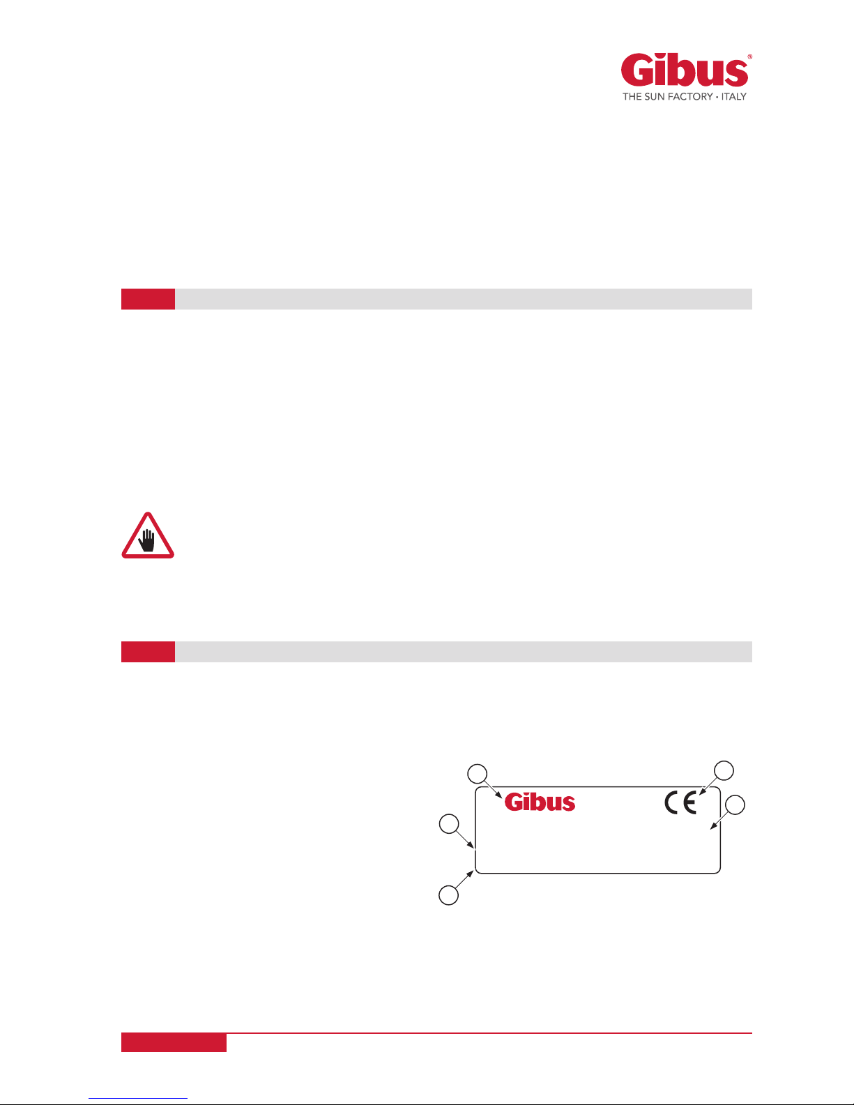
Each model is identified by the adhesive technical nameplate showing the CE marking (placed
on the profile breaker on the engine/winch drive) and contains the following data:
A
Name and address of the registered office of the
manufacturer.
B CE marking
C No of the European rule.
D Model of the awning and specifications (*).
E Year of manufacture.
IDENTIFICATION OF THE PRODUCT AND TECHNICAL NAMEPLATE
1.5
Each Gibus awning and pergola is unique, individually recognisable and traceable due to the
Gibus trademark 3D hologram with a unique alphanumeric serial number. All Gibus products
are supplied with the hologram (see back cover). The hologram is applied near the CE marking.
- The maintainer must always have at hand the instruction manual;
- Program all operation with the utmost care;
- Be well aware of where and how it is provided for the use and maintenance of the awning;
- Strictly follow all warnings relating to special dangers listed in this manual;
- A constant and careful preventive maintenance will always ensure a high level of operating
safety of the awning.
Never postpone needed repairs and have them carried out only by qualified personnel, and use
only original spare parts.
(*) The awning with manual start-up (version with winch) is
not fitted with the electrical characteristics „230V/50Hz.“
www.gibus.com
Page 10 of 56
USE AND MAINTENANCE MANUAL
Code MUT 088
Rev. 1
The awning was designed and built exclusively as a sunscreen to be used in the context of
civil construction, residential, commercial and other services to the community. The awning
is designed solely for the use indicated above, even if packaged with plastic or PVC tarpaulins
provides some protection against the rain. Any other use is considered improper and
inadequate and release the manufacturer from all liability for any damage caused to
persons or property. The awning offers, if properly installed, a resistance to wind load greater
than those required by the Class 3 of UNI EN 13561. It is therefore recommended the exposure
to a wind exerting a maximum pressure of 110 Newton/sqm, corresponding to the load of a
continuous wind speed not exceeding 49 km/h. It is strictly required, for the sake of safety, to
pack the awning before exceeding such a limit.
CHAPTER 2: SAFETY REQUIREMENTS
PURPOSE AND INTENDED USES OF THE AWNING
2.1
CAUTION: for safety reasons the awning must be therefore packed in case of wind
exceeding the recommended maximum exposure, hard rain, hail and snow; it is
very dangerous to leave the awning open in these cases, it can cause injury to
persons and damage to property.
IMPORTANT: For any doubt or unintended use, consult the manufacturer before
installation.
The manufacturer is not liable for malfunctions and damage if the awning:
- Is used for purposes other than those for which it is intended to;
- Is not operated and maintained in accordance with the instructions specified in this manual;
- Is not subject to regular maintenance, as prescribed, or non-original spare parts are used for
replacement.
The awning was designed and built to operate outside. It offers adequate protection of electrical
parts to water infiltration. The motors provides a degree of protection against moisture equal to
IP44.
With proper protection of electrical parts against infiltration of water, such as a protective roof, the
awning can also be used outdoors or away from the wall of a building (intended use), provided
that the system is degree of protection IP 55.
The electrical switch should be placed in a protected position, at a minimum height of 1.50 [m]
from the ground (the remote control is recommended when used by disabled individuals) and
away from dangerous areas.
USE ENVIRONMENT
2.2
CAUTION: the engines cannot be used in atmospheres posing risk of explosion.
IMPORTANT: Failure to follow the conditions for proper use, automatically voids
any warranty given by the manufacturer.
IMPORTANT: In order to use the awning for purposes other than those described
above, a specific permission given by the manufacturer is required. Failure to follow the
conditions for proper use, automatically voids any warranty given by the manufacturer.
www.gibus.com
Page 11 of 56
USE AND MAINTENANCE MANUAL
Code MUT 088
Rev. 1
CAUTION: No person shall install or place ladders or other fixed objects in such a
way as to obstruct the excursion path of the awning.
Anemometric sensor: In case of strong winds (greater than the set threshold), the closing of
the awning occurs automatically. The rate at which the wind sensor (anemometer) is recorded
during the initial start-up procedure, as described in the Use and Maintenance Manual (see
section 3.3 and instructions for the specific device).
Sun sensor: In case of sunshine the awning automatically opens The threshold at which the sun
sensor activates can be set (see section 3.3 and instructions for the specific device).
Rain sensor or pluviometric sensor: In case of prolonged rain, the awning automatically closes.
The activation level of the device for measuring the amount of rainfall in a given time interval (rain
gauge), is recorded during the initial start-up procedure (see section 3.3 and instructions for the
specific device).
OPTIONAL SAFETY DEVICES
2.3
The normal use of the awning is allowed to everyone, except those younger than 12 years.
The installation of the awning and of the electrical system, the adjustment of the awning
and the setting of the engine limit switch, as well as maintenance must be performed by
qualified personnel only. The installation of the awning must be carried out strictly in
accordance with the manufacturer's instructions provided in this manual and especially
following the attached INSTALLATION INSTRUCTIONS referred to in the pertinent sections
of this manual (Chap. 6 and Chap. 7).
USER AND INSTALLER REQUIREMENTS
2.4
In the manual and especially in the attached INSTALLATION INSTRUCTIONS referred to in the
pertinent sections of this manual (Chap. 6 and Chap. 7), are listed all instructions for proper
handling, storage, installation, use and maintenance of the awning, in compliance with the
"Machinery Directive" and product standards to avoid harm to people or damage to the awning
itself. Are also given instructions to perform properly both dismantling and disposal.
RECOMMENDATIONS
2.5
WARNING: The installation of the awning and its electrical connection,
are only to be carried out by specialized and authorized staff.
ANY OPERATION ON THE ELECTRICAL SYSTEM MUST BE CARRIED
OUT BY TRAINED PERSONNEL ONLY. IMPORTANT: For any doubt or
unintended use, consult the manufacturer before installation.
WARNING: The installation of the awning must be carried out strictly in accordance
with the instructions in this manual. A different installation could result in
hazardous situations.
IN THIS REGARD SEE THE SECTIONS "SAFE INSTALLATION" and "INSTRUCTIONS
FOR PROPER INSTALLATION" and the documents referred to in those sections
attached to this manual and inside the package.
ATTENTION!: Corrosion resistance is not guaranteed in the event of immersion or
sprays with salt water (sea storms, etc.). Also, with intense exposure to salty fog,
incrustations or bubbles could appear in the connections or aluminium profiles
and oxide or rust could appear on the stainless steel brackets. These conditions
are not covered by warranty.
www.gibus.com
Page 12 of 56
USE AND MAINTENANCE MANUAL
Code MUT 088
Rev. 1
WARNING: You can not alter or modify the awning. Any changes or modifications
made without proper authorization by the manufacturer, relieves the latter from
any liability for any damage that may result and automatically void the warranty.
ATTENTION: it is strictly forbidden to carry out operations using open flames in
the vicinity of the awning.
The awning is prepared for the installation of a protection roof.
CHAPTER 3: TECHNICAL DESCRIPTION
STRUCTURAL AND MECHANICAL COMPONENTS
3.1
The awning of the MEDISOLAFLY R line were designed and built according to the principles
of constant innovation, impeccable workmanship and attention to the details of Gibus Total
Quality. A system of values designed to ensure complete customer satisfaction.
The FREESTANDING MEDISOLAFLY R is a pergola- style awning integrated into a special self-
supporting structure that is freestanding and detached from any building.
For the LEANING MEDISOLAFLY R the specific structure is leaned against the wall of a building.
A spring system means that the awning fabric is taut in all 3 positions, thanks to the lateral springoperated pantographs that give the fabric its curved shape. This ensures that the fabric is always
sloping (single or double slope) for water drainage and excellent resistance to wind.
The drive of the fabric cover is motorized or provided by a winch.
The awning is equipped with several patented systems to facilitate and speed up the installation
work and improve the performance of the product:
The “pergola type” awning is equipped with a bearing structure to be fixed to the floor or to
the wall and to the floor, made of painted aluminium with guides, transverse profiles and leg of
70x130 section.
Connections include stainless steel brackets, painted aluminium casts, stainless steel bolts and
nuts. Painted aluminium section break profiles measuring 40x50.
Transmission system on side guides and very strong toothed belt, moving on roller bearings.
Aluminium cast casing with belt tension regulation.
Slide carriages with wheels with stainless steel bearings and pins.
The guide profiles, section breaks and terminals, supporting structural beams are Anticorodal EN
AW 6060 UNI EN 573-03 UNI EN 755-2, and then treated with anticorrosion phosphochromatisation
and painted with thermosetting polyester powder paints.
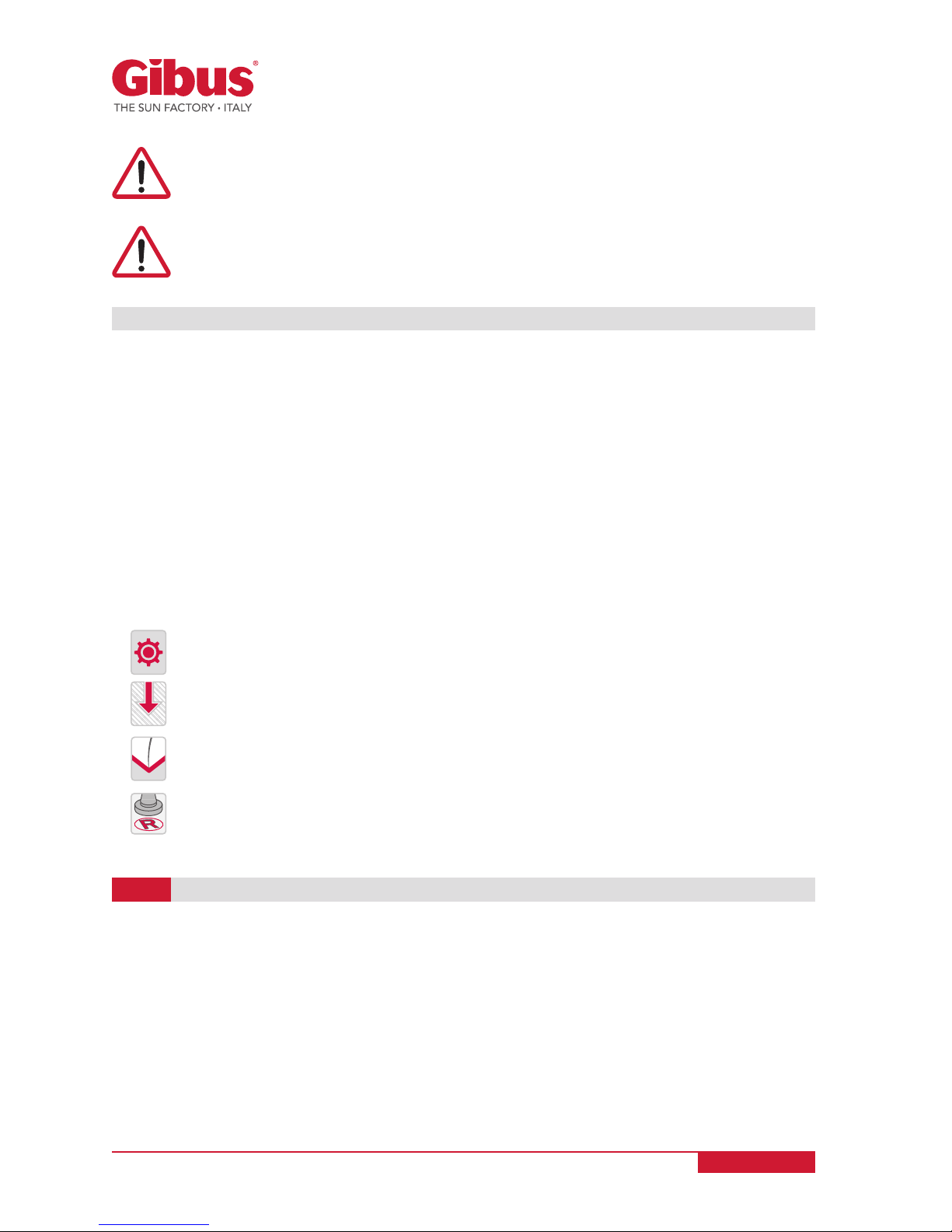
Gibus Patent
®
Fast Coupling: Quick coupling system of the engine built into the gears.
Gibus Patent
®
Quick Block: Quick coupling system of the sliding trolley with the terminal
or the profile breaker.
Gibus Patent
®
Telo FLY: To tighten the arched cover fabric with pantograph system.
Registered design.
www.gibus.com
Page 13 of 56
USE AND MAINTENANCE MANUAL
Code MUT 088
Rev. 1
The tubular motors are single-phase asynchronous irreversible equipped with thermal
protection at 140°C for safety devices against overheating. They are equipped with a
condenser, electromechanical brake assembly, two limit switches and mechanical scaler for the
reduction of primary turns at 12 or 17 [rev/min] ouputs.
The type of engine used on the awnings is indicated in the product sheet.
ELECTRICAL COMPONENTS
3.2
CAUTION: MOTOR REDUCERS have degree of protection IP 44, watertight and are
in insulation class 1 (compulsory grounding).
IMPORTANT: The instructions specific for engines are supplied upon delivery of
the awning. These instructions must be read carefully, annexed to this manual and
keep in good condition for any subsequent consultation by the customer.
Declarations of Conformity of the engine can be found in the restricted areas of
the sites supplying them.
ELECTRONIC COMPONENTS OF THE AWNING (OPTIONAL)
3.3
Upon optional request the awning can be managed electronically in its functions with control
of the weather conditions. In this case, the awning can be fitted with the following additional
electronic devices: automatic control unit for wing or automatic control unit of sun and wing or
rain gauge (see par. 2.3).
The type of electronic component used on the awning is indicated in the product sheet.
CAUTION: Never set the wind speed above the wind resistance of the awning itself
(maximum threshold recommended for MEDISOLAFLY R: 40 Km/h).
Response time:
• Detection of the wind : 3 seconds after up command.
• Presence of sun : 2 minutes after down command.
• Disappearance of the sun : 15 minutes after up command.
ATTENTION!: Corrosion resistance is not guaranteed in the event of immersion or
sprays with salt water (sea storms, etc.). Also, with intense exposure to salty fog,
incrustations or bubbles could appear in the connections or aluminium profiles
and oxide or rust could appear on the stainless steel brackets. These conditions
are not covered by warranty.
The aluminium casts are in EN AB 46100 and EN AB 44100 alloys.
The casted components for the sliding carriages, pulleys and other plastic components are
made from fiberglass reinforced nylon or Ryton® PPS. Toothed belt with steel strands. Stainless
steel screws.Stainless steel plates.
IMPORTANT: The specific installation, use and maintenance instructions of the
units are attached to the packaging of the units themselves, delivered with the
awning. These instructions must be read carefully, attached to this manual and
kept in good condition for future reference on part of the customer.
www.gibus.com

Page 14 of 56
USE AND MAINTENANCE MANUAL
Code MUT 088
Rev. 1
The type of fabric used on the awning is indicated in the product sheet. For the type of
fabric recommended for each model, refer to current price list.
PACKAGING THE FABRIC COVERS
Seams: made with TENARA wire
®
by GORE in PTFE (polytetrafluoroethylene) unaffected by UV
rays and chemical agents; they are guaranteed for 10 years.
Seals of PVC tissue by fusion.
Trimming: 100% acrylic fibre.
The fabric can be of the following types:
PVC Precontraint 602 fabric - BLOCK-OUT
PVC polyester coated on 2 sides and glossy lacquered. Black coating on the inside. 730 g/mq.
Breaking load: warp 250 kg - weft 220 kg plot (DIN 53354). 100% Waterproof - Fireproof Class 2.
PVC Poly HR Opatex fabric
PVC coated polyester inner side, outside corrugated with dust-proof acrylic paint. Double inner
black coating. 850gr/mq. Tear strength: warp 250 Kg, weft 250 Kg (DIN 53354). Fireproof class 2
PVC Precontraint 302 fabric
PVC polyester coated on 2 sides and glossy lacquered. 480 g/mq. Breaking load: warp 140 kg weft 15 kg (DIN 53354). 100% Waterproof - Fireproof Class 2.
SOLTIS 86 fabric
1100 dtex polyester coated on 2 perforated PVC sides and glossy lacquered. 380 g/mq. Breaking
strength: warp 230 kg - weft 160 kg Fireproof class 1 UNI 9177-87.
SOLTIS 92 shading fabric
1100 dtex polyester coated on 2 perforated PVC sides and glossy lacquered. 420 g/mq. Breaking
strength: warp 310 kg - weft 210 kg Fireproof class 1 UNI 9177-87.
SOLTIS 96-W96 fabric
1100 dtex polyester coated on 2 perforated PVC sides and glossy lacquered. 400 g/mq. Breaking
strength: warp 220 kg - weft 220 kg Fireproof class 1 UNI 9177-87. Only W96 100% Waterproof
TS light polyester fabric
100% polyester mass dyed outdoor 300g/mq. Breaking load: warp 210kg - weft 140Kg (UNI EN
ISO 13934-1/2000). Water Column ≥ 300mm (UNI EN 20811). Waterproof (UNI EN 24920). Oil
resistance value 5 (AATCC118). Resistant to dirt, excellent dimensional stability.
TS heavy polyester fabric
100% polyester mass dyed outdoor 360g/mq. Breaking load: warp 210kg - weft 180Kg (UNI EN
ISO 13934-1/2000). Water Column ≥ 1000mm (UNI EN 20811). Waterproof (UNI EN 24920). Oil
resistance value 5/6 (AATCC118). Resistant to dirt, excellent dimensional stability.
TS polyester fabric, waterproof and resin treated
100% polyester mass dyed outdoor 360g/mq. Breaking load: warp 190 Kg - weft 120Kg (UNI EN ISO
13934-1/2000). Water Column ≥ 700mm (UNI EN 20811). Waterproof (UNI EN 24920). Oil resistance
value 5 (AATCC118). Resistant to dirt, excellent dimensional stability.TS FR fireproof polyester
fabric: Class 1 UNI EN 9177 - Class B1 DIN 4102
100% polyester mass-dyed outdoor 375g/mq. Breaking load: warp 210 kg - weft 180Kg (DIN EN ISO
13934-1/2000). Water Column ≥ 300mm (UNI EN 20811). Waterproof (UNI EN 24920). Oil resistance
value 5 (AATCC118). Resistant to dirt, excellent dimensional stability.
Acrylic Fabric
100% "outdoor" used acrylic fibre, mass-dyed 300 g/sqm. Stain-proof - anti-decay - water-proof
with Teflon treatment. Breaking load: warp 130 kg - weft 80 kg (UNI 8639). Water-proof (UNI EN
24920) Water column > 300 mm (UNI 5122).
FABRIC COMPONENTS
3.4
www.gibus.com
Page 15 of 56
USE AND MAINTENANCE MANUAL
Code MUT 088
Rev. 1
The European Regulation EU 528/2012 regulates the marketing and use of biocidal
products: antifungal agents or aimed at making harmless other organisms.
Liberty Acrylic Fabric
100% "outdoor" used acrylic fibre, mass-dyed 350 g/sqm. Stain-proof - anti-decay - water-proof with
Teflon treatment. Breaking load: warp 160 kg - weft 115 kg (UNI 5122). Water-proof (UNI EN 24920)
Water column > 400 mm (UNI 8639).
Acrylic Printed Fabric
100% "outdoor" used acrylic fibre, mass-dyed 340 g/sqm. Stain-proof - anti-decay - water-proof with
Teflon treatment. Breaking load: warp 130 kg - weft 80 kg (UNI 8639). Water-proof (UNI EN 24920)
Water column > 1000 mm (UNI 5122).
Cristal PLUS 500 2S
PVC film stabilized for UV rays. 628 g / sqm, thickness 0.5 mm. 100% waterproof Tensile strength:
length 220 kg /cmq - height 210 kg /cmq (ASTM D882). On request: FR version with fire resistance
class 2.
Vinitex 3X3
Translucent laminated PVC with polyester support. 500 g/mq. 1100 Dtex polyester warp and weft,
100% waterproof. Tensile strength: warp 57 daN/5cm plot - weft 59 daN/5cm (EN ISO 1421).
BIOCIDALPRODUCTS
3.6
COMPLEMENTARY MATERIALS
3.5
IMPORTANT: the fabrics used are guaranteed for a period of 5 years, following a
normal exposure to the action of the sun and atmospheric agents in general, and
the action of moulds and micro-organisms.
ATTENTION: Some of the fabrics used by Gibus to package its products undergo
treatments with biocidal products. For more information and to know the type of
biocidal product possibly used in treating the fabric of your awning please visit
our website: www.gibus.com
IMPORTANT! THE CRISTAL IS GUARANTEED FOR 2 YEARS.
The measured noise (sound pressure level) was less than 70 dB (A).
NOISE LEVEL
3.7
www.gibus.com
Page 16 of 56
USE AND MAINTENANCE MANUAL
Code MUT 088
Rev. 1
TYPE
4.1
CHAPTER 4: TECHNICAL DATA
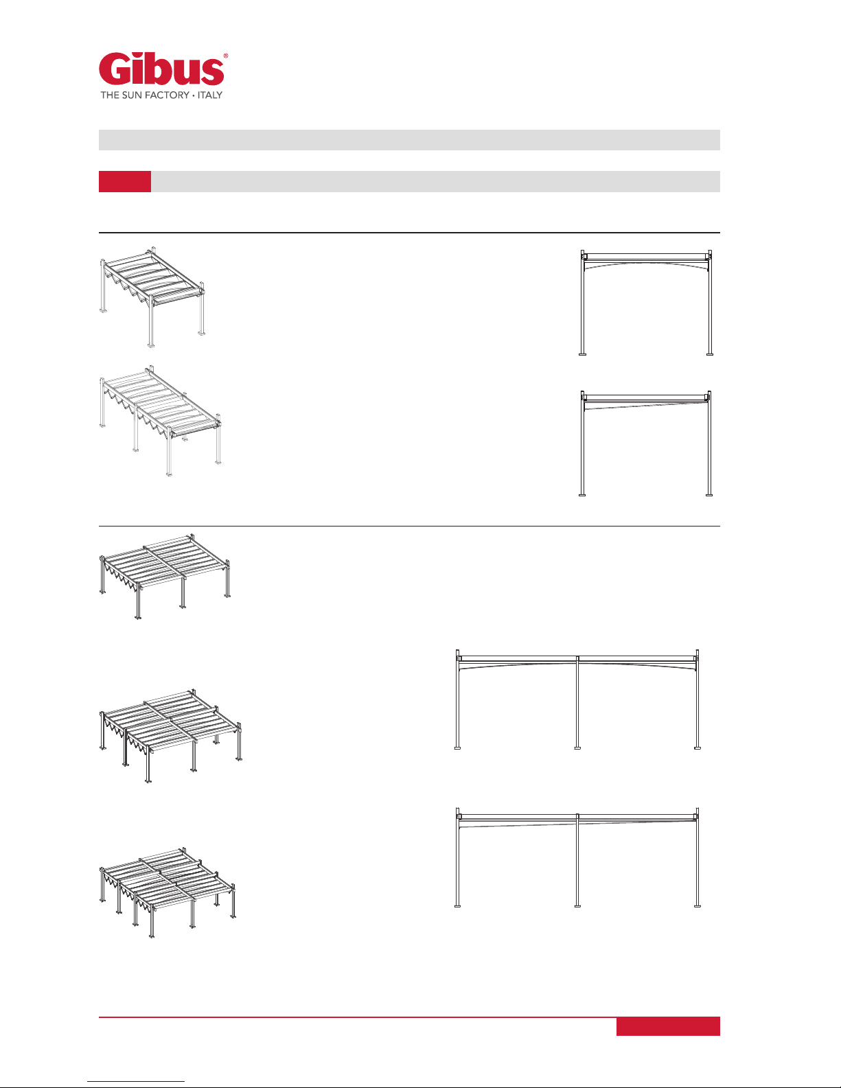
SINGLE MODULE FREESTANDING MEDISOLAFLY R:
DOUBLE MODULE FREESTANDING MEDISOLAFLY R:
With 4 posts:
Projection until 480 cm
With 6 posts:
Projection until 420+50 cm
With 6 posts:
Projection from 540 to 780 cm
With 8 posts:
Projection from 480+50 cm to 540+50 cm
With 10 posts:
Projection from 600+50 cm to 660+50 cm
Bilateral water
drainage
with double
pantograph
(standard)
Bilateral water
drainage
with double
pantograph
(standard)
Lateral water
drainage (left or
right) with single
pantograph
Lateral water
drainage (left or
right) with single
pantograph
www.gibus.com
CON SCARICO LATERALE
CON MONOPANTOGRAFO
Page 17 of 56
USE AND MAINTENANCE MANUAL
Code MUT 088
Rev. 1
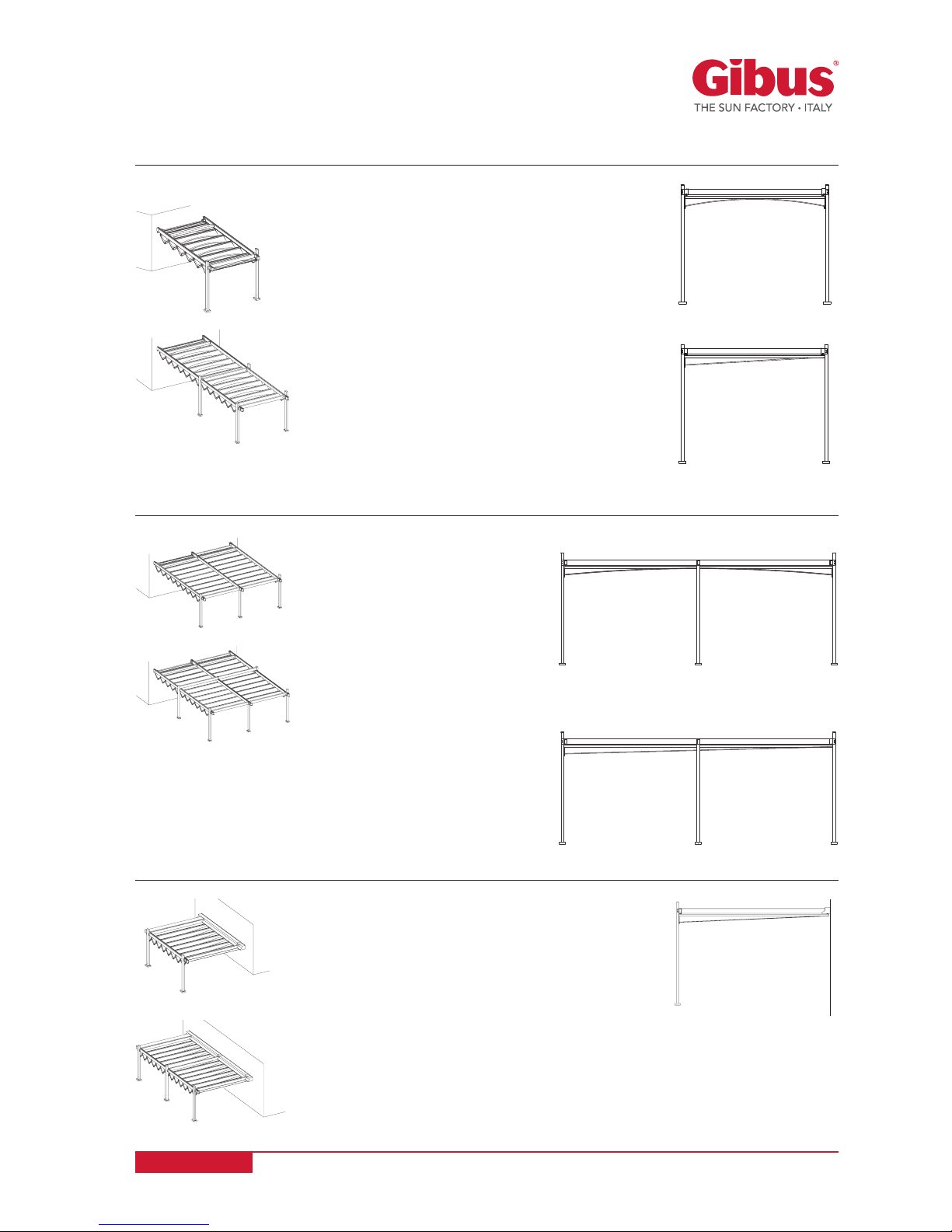
SINGLE MODULE FRONTAL LEANING VERSION MEDISOLAFLY R:
SINGLE MODULE LATERAL LEANING VERSION MEDISOLAFLY R:
DOUBLE MODULE FRONTAL LEANING VERSION MEDISOLAFLY R:
With 2 posts:
Projection until 480+30 cm
With 2 posts:
Width until 480 cm
With 3posts:
Width from 540 to 780 cm
With 3 posts:
Projection until 480+60 cm
With 4 posts:
Projection from 540+30 cm to 780+30 cm
With 5 posts:
Projection from 540+60 cm to 660+60 cm
Bilateral water
drainage
with double
pantograph
(standard)
Bilateral water
drainage
with double
pantograph
(standard)
Lateral water
drainage (left or
right) with single
pantograph
Lateral water
drainage (left or
right) with single
pantograph
Lateral water
drainage (left or
right) with single
pantograph
www.gibus.com

13214
4.5
4
~ 208,5
285
I
254
F
TL
G
T
LI
HT
S
S
1
S L
Page 18 of 56
USE AND MAINTENANCE MANUAL
Code MUT 088
Rev. 1
MEDISOLAFLY R - ISLAND
4.2
Central post base
with post base protective
cover
ISLAND
FREESTANDING
SINGLE MODULE
ISLAND
FREESTANDING
DOUBLE MODULE
Post base with
Cover
Standard (only on
central post base)
Post base without
Cover
on request
Aligned post base
Front Back
Aligned post base
Left and Right
4 posts 6 posts 6 posts 8 posts 10 posts
Freestanding
1 Module
Freestanding
2 Modules
S
projection
S
1
projection
F
profile
breaker
I
Wheelbase
section
breaking unit
LI
Packaging overall
dimensions
HT
height
240 290 (240+50) 5
60
43
45,5
300 350 (300+50) 6 49
360 410 (360+50) 7 55
420 470 (420+50) 8 61
480 530 (480+50) 9 67
540 590 (540+50) 10 73
600 650 (600+50) 11 79
660 710 (660+50) 12 85
720 - 13 91
780 - 14 97
www.gibus.com

Page 19 of 56
USE AND MAINTENANCE MANUAL
Code MUT 088
Rev. 1
Legend:
A = Total weight of the awning: this refers to the total weight of the awning including bearing structure and fabric cover.
B = Weight of the fabric covers: this refers to the weight of just the fabric cover (including the opatex fabric).
T = Roof (optional) G = Legs
F = Profile breaker TL = Fabric covers
OPTIONAL
• Transparent PMMA canopy without edge profiles
• Guide metal sheet plugs
• Stainless steel ball bearings
ACCESSORIES
• Led Linear
IMPORTANT: For each size the load shown in the table is greater than the one provided
by Class 3 - UNI EN 13561 / UNI EN 1932 (safety load continuously distributed on the
extended surface equal to 13.5 [kg/m2] or 132 [N/m2 ]).
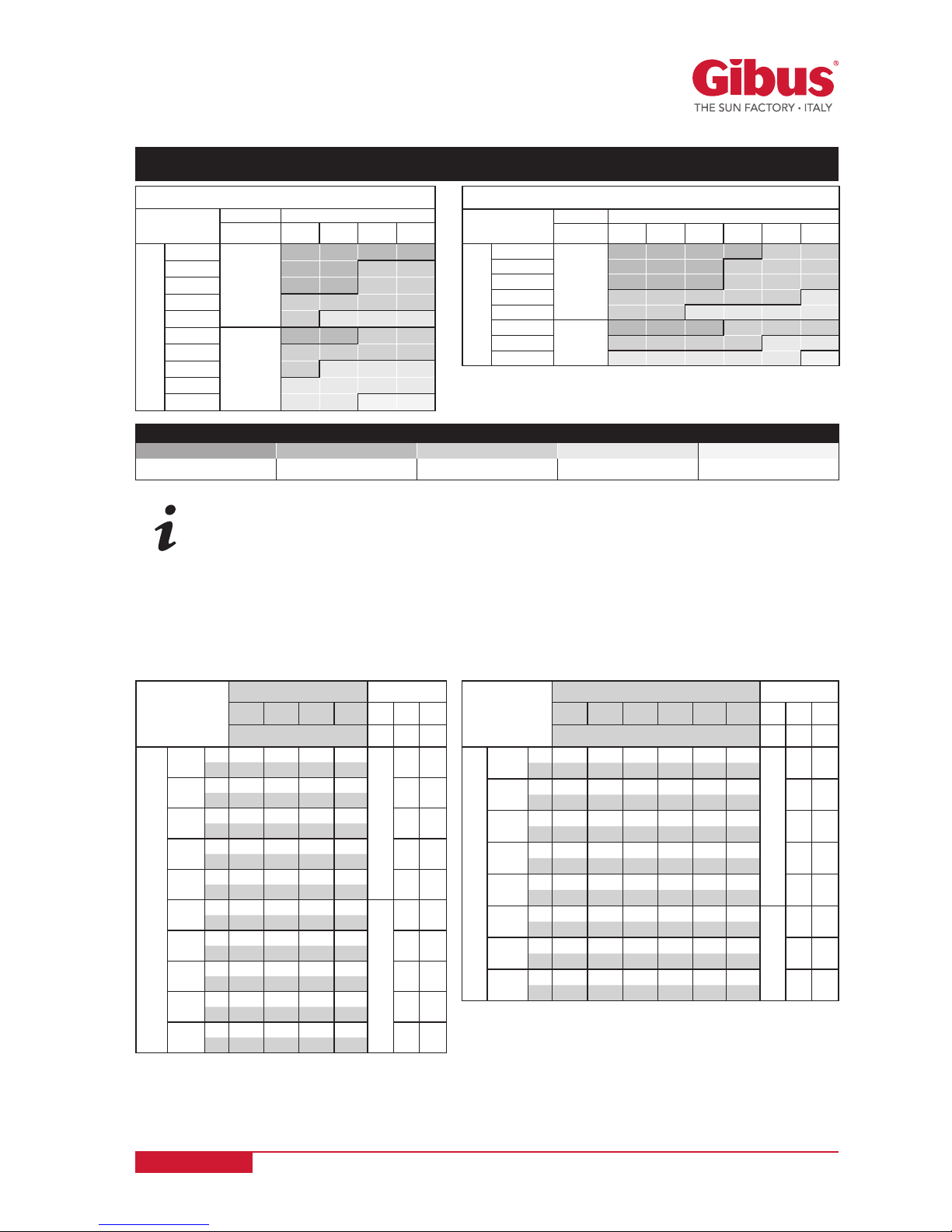
LEGEND - “BEAUFORT” WIND SCALE
GRADE 10 (10) GRADE 9 (9) GRADE 8 (8) GRADE 7 (7) GRADE 6 (6)
Storm Strong gale Gale Strong wind Wind
Table of maximum tolerable wind load values per square meter awning [kg/m2]
depending on the size of the awning:
Freestanding
single
module
WIDTH “L” (cm)
250 300 350 400 G F TL
Kg n° n° n°
PROJECTION “S” (cm)
240
A 192 203 218 229
4
5 4
B 36 41 45 50
300
A 203 215 231 243
6 5
B 42 47 53 58
360
A 214 228 244 258
7 6
B 47 54 60 66
420
A 228 242 261 275
8 7
B 53 60 67 74
480
A 240 255 274 289
9 8
B 58 66 74 82
540
A 279 297 319 336
6
10 9
B 64 73 82 90
600
A 290 309 332 351
11 10
B 70 79 89 98
660
A 304 324 349 368
12 11
B 75 86 96 106
720
A 316 336 362 383
13 12
B 81 92 103 115
780
A 327 349 375 397
14 13
B 86 98 110 123
Freestanding
double module
WIDTH “L” (cm)
450 500 550 600 650 700 G F TL
Kg n° n° n°
PROJECTION “S” (cm)
240
+50
A 328 341 359 372 390 404
6
5 4
B 69 74 79 84 89 94
300
+50
A 345 360 378 393 411 426
6 5
B 78 84 89 95 101 107
360
+50
A 363 379 398 413 433 448
7 6
B 87 93 100 107 114 121
420
+50
A 384 401 422 439 460 476
8 7
B 96 103 111 119 126 134
480
+50
A 402 420 441 459 481 498
8
9 8
B 105 113 122 130 139 147
540
+50
A 445 465 490 510 535 555
10 9
B 114 123 132 142 151 160
600
+50
A 463 484 509 530 556 577
10
11 10
B 123 133 143 153 164 174
660
+50
A 494 516 544 566 593 615
12 11
B 132 143 154 165 176 187
FREESTANDING SING LE M ODU LE
WIDTH (cm)
posts 250 300 350 400
PROJECTION (cm)
240
4
95
(9)
95
(9)
71
(9)
57
(9)
300 95
(9)
95
(9)
69
(8)
55
(8)
360 92
(9)
92
(9)
67
(8)
53
(8)
420 67
(8)
65
(8)
65
(8)
51
(8)
480 51
(7)
49
(7)
49
(7)
45
(7)
540
6
95
(9)
95
(9)
69
(8)
55
(8)
600 67
(8)
65
(8)
65
(8)
51
(8)
660 51
(7)
49
(7)
49
(7)
45
(7)
720 40
(7)
38
(7)
36
(7)
33
(7)
780 33
(7)
31
(7)
30
(6)
28
(6)
FREESTANDING DOUB LE M ODU LE
WIDTH (cm)
posts 450 500 550 600 650 700
PROJECTION (cm)
240+50
6
95
(9)
95
(9)
92
(9)
71
(9)
57
(8)
55
(8)
300+50 95
(9)
95
(9)
92
(9)
69
(8)
55
(8)
53
(8)
360+50 92
(9)
92
(9)
88
(9)
67
(8)
53
(8)
51
(8)
420+50 67
(8)
65
(8)
65
(8)
60
(8)
51
(8)
49
(6)
480+50
8
92
(9)
92
(9)
90
(9)
67
(8)
53
(8)
51
(8)
540+50 67
(8)
65
(8)
62
(8)
60
(8)
51
(8)
49
(8)
600+50
10
75
(9)
71
(9)
60
(8)
55
(8)
49
(7)
33
(7)
660+50 49
(7)
49
(7)
40
(7)
36
(7)
33
(7)
30
(6)
www.gibus.com

S1
S
13214
4.5
4
~ 208,5
285
I
254
F
TL
G
T
LI25
HT
S L
Page 20 of 56
USE AND MAINTENANCE MANUAL
Code MUT 088
Rev. 1
MEDISOLAFLY R - FRONTAL LEANING VERSION
4.3
Central post base
with post base protective
cover
FRONTAL
LEANING
VERSION
SINGLE MODULE
FRONTAL
LEANING
VERSION
DOUBLE MODULE
Post base with
Cover
Standard (only on
central post base)
Post base without
Cover
on request
Aligned post base
Front Back
Aligned post base
Left and Right
2 posts 4 posts 3 posts 5 posts
Frontal
leaning version
single module
Frontal
leaning version
double module
S
projectionS1projection
F
profile
breaker
I
Wheelbase
section
breaking unit
LI
Packaging
overall
dimensions
HT
height
270 (240+30) 300 (240+60) 5
60
43
45,5
330 (300+30) 360 (300+60) 6 49
390 (360+30) 420 (360+60) 7 55
450 (420+30) 480 (420+60) 8 61
510 (480+30) 540 (480+60) 9 67
570 (540+30) 600 (540+60) 10 73
630 (600+30) 660 (600+60) 11 79
690 (660+30) 720 (660+60) 12 85
750 (720+30) - 13 91
810 (780+30) - 14 97
www.gibus.com
Page 21 of 56
USE AND MAINTENANCE MANUAL
Code MUT 088
Rev. 1
Legend:
A = Total weight of the awning: this refers to the total weight of the awning including bearing structure and fabric cover.
B = Weight of the fabric covers: this refers to the weight of just the fabric cover (including the opatex fabric).
T = Roof (optional) G = Legs
F = Profile breaker TL = Fabric covers
OPTIONAL
• Transparent PMMA canopy without edge profiles
• Guide metal sheet plugs
• Stainless steel ball bearings
ACCESSORIES
• Led Linear
IMPORTANT: For each size the load shown in the table is greater than the one provided
by Class 3 - UNI EN 13561 / UNI EN 1932 (safety load continuously distributed on the
extended surface equal to 13.5 [kg/m2] or 132 [N/m2 ]).
Table of maximum tolerable wind load values per square meter awning [kg/m2]
depending on the size of the awning:
LEGEND - “BEAUFORT” WIND SCALE
GRADE 10 (10) GRADE 9 (9) GRADE 8 (8) GRADE 7 (7) GRADE 6 (6)
Storm Strong gale Gale Strong wind Wind
Frontal
leaning version
single module
WIDTH “L” (cm)
250 300 350 400 G F TL
Kg n° n° n°
PROJECTION “S” (cm)
240
+30
A 166 177 192 203
2
5 4
B 36 41 45 50
300
+30
A 177 190 205 218
6 5
B 42 47 53 58
360
+30
A 189 202 218 232
7 6
B 47 54 60 66
420
+30
A 203 217 235 249
8 7
B 53 60 67 74
480
+30
A 214 229 249 264
9 8
B 58 66 74 82
540
+30
A 253 271 293 311
4
10 9
B 64 73 82 90
600
+30
A 264 283 306 325
11 10
B 70 79 89 98
660
+30
A 279 298 323 343
12 11
B 75 86 96 106
720
+30
A 290 310 336 357
13 12
B 81 92 103 115
780
+30
A 301 323 349 371
14 13
B 86 98 110 123
Frontal
leaning version
double module
WIDTH “L” (cm)
450 500 550 600 650 700 G F TL
Kg n° n° n°
PROJECTION “S” (cm)
240
+60
A 289 302 319 333 350 364
3
5 4
B 69 74 79 84 89 94
300
+60
A 307 321 339 354 372 386
6 5
B 78 84 89 95 101 107
360
+60
A 324 340 359 374 393 409
7 6
B 87 93 100 107 114 121
420
+60
A 347 363 384 400 421 437
8 7
B 96 103 111 119 126 134
480
+60
A 364 382 403 421 442 460
9 8
B 105 113 122 130 139 147
540
+60
A 382 400 423 441 464 482
5
10 9
B 114 123 132 142 151 160
600
+60
A 420 439 462 482 505 524
11 10
B 123 133 143 153 164 174
660
+60
A 443 463 488 508 533 554
12 11
B 132 143 154 165 176 187
FRONTAL LEANING VERSION SIN GLE MO DUL E
WIDTH (cm)
posts 250 300 350 400
PROJECTION (cm)
240+30
2
98
(9)
95
(9)
71
(9)
57
(9)
300+30 95
(9)
95
(9)
69
(8)
55
(8)
360+30 92
(9)
92
(9)
67
(8)
53
(8)
420+30 67
(8)
65
(8)
65
(8)
51
(8)
480+30 51
(8)
49
(7)
49
(7)
45
(7)
540+30
4
95
(9)
95
(9)
69
(8)
55
(8)
600+30 65
(8)
65
(8)
65
(8)
51
(8)
660+30 51
(8)
49
(7)
49
(7)
45
(7)
720+30 40
(7)
38
(7)
36
(7)
33
(7)
780+30 33
(7)
31
(7)
30
(6)
28
(6)
FRONTAL LEANING VERSION DOU BLE MO DUL E
WIDTH (cm)
posts 450 500 550 600 650 700
PROJECTION (cm)
240+30
3
98
(9)
95
(9)
95
(9)
71
(9)
57
(8)
55
(8)
300+30 95
(9)
95
(9)
92
(9)
69
(8)
55
(8)
53
(8)
360+30 92
(9)
92
(9)
90
(9)
67
(8)
53
(8)
51
(8)
420+30 67
(8)
65
(8)
65
(8)
60
(8)
51
(8)
49
(7)
480+30 51
(8)
51
(8)
49
(7)
49
(7)
40
(7)
36
(7)
540+30
5
80
(9)
75
(9)
71
(9)
65
(8)
55
(8)
51
(8)
600+30 65
(8)
62
(8)
60
(8)
55
(8)
49
(7)
33
(7)
660+30 49
(7)
49
(7)
40
(7)
36
(7)
33
(7)
30
(6)
www.gibus.com
S
285
~ 208,5
I
254
F
TL
G
T
13214
4.5
4
S
L
LI
HT
Page 22 of 56
USE AND MAINTENANCE MANUAL
Code MUT 088
Rev. 1
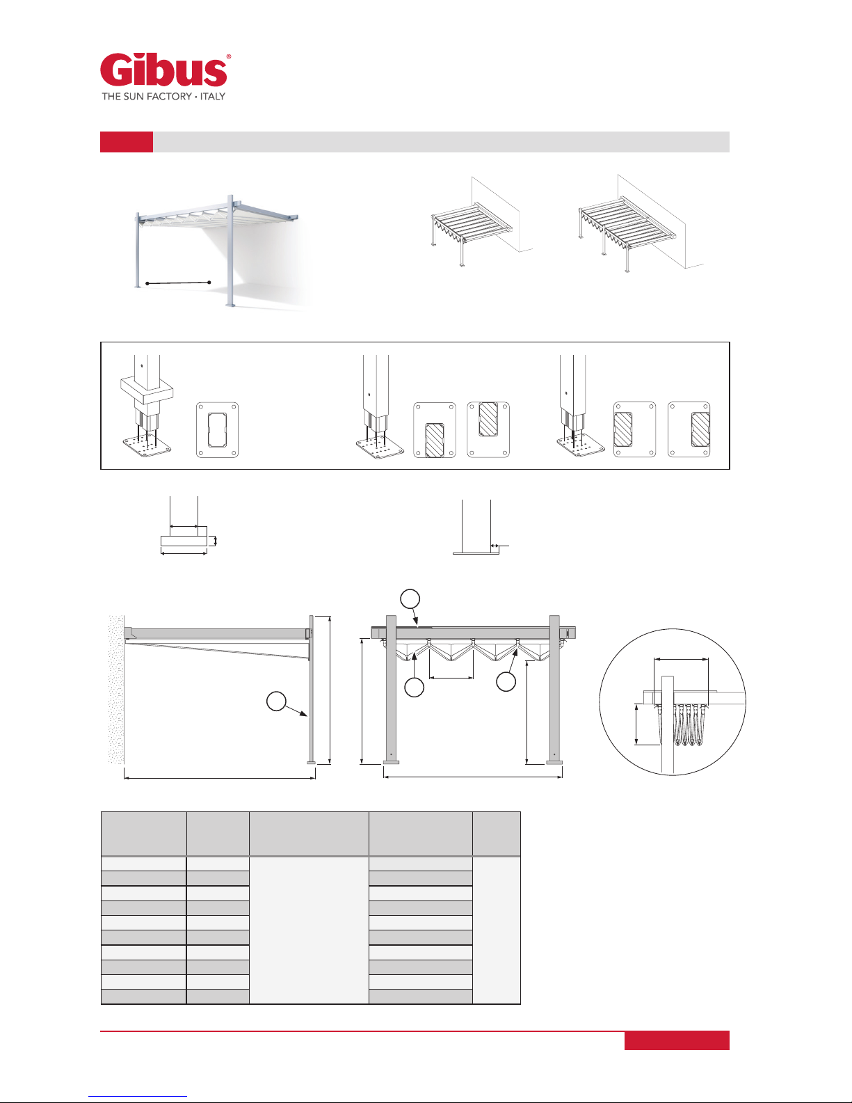
MEDISOLAFLY R - LATERAL LEANING VERSION
4.4
Central post base
with post base protective
cover
LATERAL LEANING
VERSION
SINGLE MODULE
Post base with Cover
Standard
(only on central post base)
Post base without Cover
on request
Aligned post base
Front Back
Aligned post base
Left and Right
2 posts 3 posts
L
widht
F
profile
breaker
I
Wheelbase section
breaking unit
LI
Packaging overall
dimensions
HT
height
274 (240+34) 5
60
43
45,5
334 (300+34) 6 49
394 (360+34) 7 55
454 (420+34) 8 61
514 (480+34) 9 67
574 (540+34) 10 73
634 (600+34) 11 79
694 (660+34) 12 85
754 (720+34) 13 91
814 (780+34) 14 97
www.gibus.com

Page 23 of 56
USE AND MAINTENANCE MANUAL
Code MUT 088
Rev. 1
Legend:
A = Total weight of the awning: this refers to the total weight of the awning including bearing structure and fabric cover.
B = Weight of the fabric covers: this refers to the weight of just the fabric cover (including the opatex fabric).
T = Roof (optional) G = Legs
F = Profile breaker TL = Fabric covers
OPTIONAL
• Transparent PMMA canopy without edge profiles
• Guide metal sheet plugs
• Stainless steel ball bearings
ACCESSORIES
• Led Linear
IMPORTANT: For each size the load shown in the table is greater than the one provided
by Class 3 - UNI EN 13561 / UNI EN 1932 (safety load continuously distributed on the
extended surface equal to 13.5 [kg/m2] or 132 [N/m2 ]).
LEGEND - “BEAUFORT” WIND SCALE
GRADE 10 GRADE 9 GRADE 8 GRADE 7 GRADE 6
Storm Strong gale Gale Strong wind Wind
Table of maximum tolerable wind load values per square meter awning [kg/m2]
depending on the size of the awning:
LATERAL LEANING VERSION SIN GLE MO DUL E
WIDTH (cm)
240+34 300+34 360+34 420+34 480+34 540+34 600+34 660+34 720+34 780+34
PROJECTION (cm)
250 100
(9)
100
(9)
95
(9)
92
(9)
65
(8)
100
(9)
95
(9)
65
(8)
49
(8)
40
(8)
300 95
(9)
95
(9)
92
(9)
70
(8)
55
(8)
95
(9)
65
(8)
49
(7)
40
(7)
33
(7)
350 95
(9)
95
(9)
92
(9)
65
(8)
49
(7)
92
(9)
62
(8)
49
(7)
38
(7)
31
(7)
400 71
(9)
69
(8)
67
(8)
60
(8)
47
(7)
69
(8)
58
(8)
49
(7)
36
(7)
30
(6)
450 57
(8)
55
(8)
53
(8)
51
(7)
45
(7)
55
(8)
51
(7)
49
(7)
33
(7)
28
(6)
posts 2 3
Lateral
leaning version
single module
WIDTH “L” (cm)
240+34 300+34 360+34 420+34 480+34 540+34 600+34 660+34 720+34 780+34
Kg
PROJECTION “S” (cm)
250
A 174 186 197 212 223 235 247 261 273 284
B 36 42 47 53 58 64 70 75 81 86
300
A 186 199 212 227 240 252 265 280 293 305
B 41 47 54 60 66 73 79 86 92 98
350
A 202 216 230 246 260 274 287 304 318 331
B 45 53 60 67 74 82 89 96 103 110
400
A 215 229 244 262 276 291 305 323 338 352
B 50 58 66 74 82 90 98 106 115 123
450
A 231 246 262 281 297 312 328 348 363 379
B 54 63 72 81 90 99 108 117 126 135
G n° 2 3
F n° 5 6 7 8 9 10 11 12 13 14
TL n° 4 5 6 7 8 9 10 11 12 13
www.gibus.com
Page 24 of 56
USE AND MAINTENANCE MANUAL
Code MUT 088
Rev. 1
The awning is packed with Nylon film and polystyrene in double walled corrugated cardboard
boxes with reinforced corners to protect the product and lock the parts in place during transport.
The components are packed in several parcels given the size and weight of the product (see
TECHNICAL TABLE Chap. 4). The weight of each package can be high, the result is the need for
manual handling in two or more persons whenever the weight exceeds 25 kg.
In order to facilitate transport by operators, check the weight of the awning depending on
its size shown in the TEHCNICAL TABLE on Chapter 4.
For transportation to the customer’s premises by the Retailer and / or Manufacturer, it is required
to fill the support points on racks to prevent scratches to the structure or to the fabric cover.
Product integrity must be preserved until delivery to the customer. Damage to the product
caused by the dismantling of the awning and subsequent handling and / or transportation
performed after installation, are not covered by warranty. To avoid hazardous situations observe
the following safety requirements:
CHAPTER 5: PACKING, HANDLING AND TRANSPORTATION
ATTENTION: Due to the size and weight of the awning and of each individual
packaging, make sure that for handling a sufficient number of people is available,
so that the weight to be loaded by each person is not more than 25 kg in the case
of manual handling (in this regard, check the weight of the awning depending on
its size in the TECHNICAL TABLES on Chapter 4).
CAUTION: Do not store packages in an upright position, or leave them unattended
in the area of installation if the awning is not yet installed; avoid leaving them
unattended in the presence of children. Avoid storage the packed or unpacked
awning outdoor area when the weather conditions are adverse (rain).
ATTENTION: Keep out of reach of children packaging materials, they can be a
source of danger to them. In particular, the Nylon film with "bubble barrier effect"
could be used so as to cause suffocation.
WARNING: If the awning is to be mounted on a higher surface than the ground,
it is necessary to define and supervise the area during the ascent to the awning,
so that no one stands at any time under the suspended load. Securely fasten the
packages of the awning in order to prevent it from falling.
IMPORTANT: unpack using scissors with rounded tips in order not to damage
the fabric, do not use cutters. The packaging material should be disposed of or
recycled in accordance with the regulations in force in the Country of destination
of the product.
www.gibus.com
Page 25 of 56
USE AND MAINTENANCE MANUAL
Code MUT 088
Rev. 1
The installation usually is not performed directly by staff from Gibus S.p.A. but by staff appointed
by the buyer or customer.
The client (user) is responsible under the law to entrust the installation to an expert staff, strictly
complying to the installation rules listed in this manual. In particular follow the "Instructions for
proper installation" in Chapter 7.
At the time of installation arrange all the tools mentioned on the first pages of the “Installation
Instructions - MEDISOLAFLY R line”.
If installers are more than one, it is necessary to appoint an operations co-ordinator.
CHAPTER 6: SAFE INSTALLATION
IMPORTANT: The installation must be performed in full compliance with the
installation instructions and safety rules in force in mobile sites. Be especially
careful when working at height.
MECHANICAL STRUCTURE
6.1
IMPORTANT: Before using the staging, scaffoldings, ladders, any lifting elements
and all personal protective device, especially when working at height (harnesses,
safety belts, etc..), make sure all comply with the requirements of the current law
on safety and are all in good conditions.
WARNING: If the awning is to be mounted on a higher surface than the ground,
it is necessary to define and supervise the area during the ascent to the awning,
so that no one stands at any time under the suspended load. Securely fasten the
packages of the awning in order to prevent it from falling.
WARNING: Operators must act in accordance with the safety instructions received.
USE SUITABLE SLING DEVICES AND PROVIDED PPE.
WARNING: Improper installation can result in bodily injury. Read and carefully
follow the installation instructions (provided with this manual) to properly secure
the structure and the fabric cover, so avoiding any risk of falls. At the time of
installation arrange all the tools mentioned on the first pages of the “Installation
Instructions - MEDISOLAFLY R line”.
ATTENTION!: the “ceiling supports” the dowels are not sheared but extracted
(the worst case condition). In this case therefore, dowels must be used able to
withstand a double load with respect to the wall supports.
ATTENTION!: The choice of dowels depends on the type and condition of the wall
(wall or ceiling) and floor. If the necessary requirements are satisfied, use alternative
technical solutions like internal counter brackets in the wall, chemical dowels or
other solutions.
www.gibus.com

Page 26 of 56
USE AND MAINTENANCE MANUAL
Code MUT 088
Rev. 1
Each column/leg has a drilled foot for fixing it to the floor with dowels.
Fix the feet to the floor only after having completely assembled the structure and ensured
that the awning opens and closes correctly.
Ensure that each foot rests on a solid firm base (a concrete base is ideal). If the structure will be
standing on soft ground (a garden or similar), prepare suitable foundation plinths beforehand for
each column/leg. The foundation surface must be much larger than the foot to ensure that each
securing hole for the dowel is completely surrounded by the foundation.
ATTENTION!: THE CHOICE OF ANCHORING DOWELS DEPENDS ON THE TYPE
AND CONDITION OF THE SITE FOR HOUSING THE STRUCTURE.
ATTENTION! In the case the structures are not considered adequate for the
installation, the installers must notify the client and record the details of the
inadequate features in the “INSTALLATION NOTES” in the section 14 of this manual.
If the minimum requirements are not satisfied, use other technical solutions, such
as preparing a suitable foundation plinth for each foot.
WARNING: Check the status of the housing and fixing site of the structure before
installing and anchoring the anchor pins.
The instructions on the installation are described in Annex “INSTALLATION INSTRUCTIONS”.
IMPORTANT!: Before hooking the awning to the supports, check that it was not
damaged during handling and transport.
www.gibus.com

Page 27 of 56
USE AND MAINTENANCE MANUAL
Code MUT 088
Rev. 1
WARNING: ALL ELECTRICAL CONNECTIONS MUST BE MADE ONLY BY
PROFESSIONALLY QUALIFIED AND TRAINED STAFF, WITH THE POWER SUPPLY
CUT OFF AND IN ACCORDANCE WITH THE REGULATIONS IN FORCE.
The final implementation of the electrical system must be strictly carried out by a qualified
electrician. Also the technical choices carried out to implement the electrical connections fall
within his competence. Below are the guidelines that should be carefully considered by the
installer who will be charged with the costs of such operating decisions.
Instructions for qualified electrical installers:
ELECTRICAL CONNECTIONS
6.2
IMPORTANT: The electrical system must be carried out according to UNI EN 60335-1, or
subsequent, in force at the time of installation. The degree of protection of the electrical
must be at least IP55; and it must provide, upstream, a differential switch and a circuit
breaker. The metal parts must be grounded.
WARNING: The switch shall have degree of protection IP 44 if mounted outside the area
accessible to third parties and at a high from the ground lower than 1.80 [m], the degree
of protection can be IP40 if the switch is mounted inside or in areas not accessible to third
parties. The switch can be of the unstable position type, “man-controlled”, or stable position
type “not man controlled”. If the switch is the type without locking, it must be fixed in view of
the awning, out of danger areas (moving parts) and at a minimum height of 1.50 [m] from
the ground.
WARNING: if the awning is installed at a height from the walkable floor greater than 2,00
m in its lowest travel point, it is not necessary to install additional safety devices even in
the case of installation of electronic control automatic or semi-automatic units.
If its lowest point is less than 2,00 m from the walkable floor, it is required the
“man controlled” command. With the installation of electronic control units it is
necessary to install a buzzer or a warning light.
IMPORTANT! Never connect two or more engines to one single switch / inverter without
using a control unit. Do not connect the two switches / inverters to a single engine.
There is a risk of induced currents resulting in damage to the engines.
IMPORTANT! Check that the mains voltage is 230 V - 50 Hz. Standard equipment is
meant to be connected to 230v/50Hz electrical mains; for the installation in countries
with different features please specify the requirements when you place the order!
The power cord should be protected by the sheath and provided by cable gland in
the cases of crossing of conductive materials.
www.gibus.com
Neutro
Blu
Fase
Marrone
Terra
Nero
Giallo/Verde
230 Vac – 50 Hz
OPTIONAL
Neutro
Azzurro
Fase
Marrone
Terra
Azzurro
Giallo/Verde
230 Vac – 50 Hz
N
L
1
1
2
2
3
3
4
4
Neutro
Blu
Fase
Marrone
Terra
Giallo/Verde
230 Vac – 50 Hz
N
L
1
2
3
1
2
3
1
2
3
OFF
230 V
~
50 Hz
3 x 1,5 mm
2
3 x 0,75 mm
2
Neutro
Blu
Fase
Marrone
Terra
Giallo/Verde
230 Vac – 50 Hz
N
L
1
2
3
Page 28 of 56
USE AND MAINTENANCE MANUAL
Code MUT 088
Rev. 1
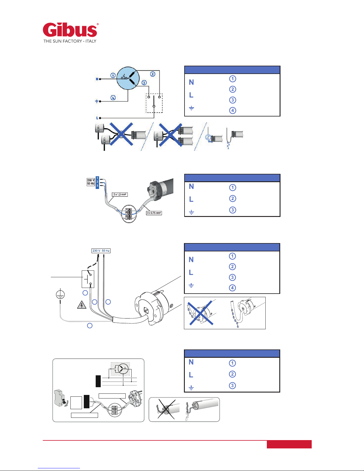
ELECTRICAL WIRING AND CONNECTIONS FOR SCS CABLATI ENGINES:
ELECTRICAL WIRING AND CONNECTIONS FOR RTS RADIO ENGINES:
ELECTRICAL WIRING AND CONNECTIONS FOR RX RADIO ENGINES:
230 Vac - 50 Hz
Neutral
Phase
Earth
Blue
Brown
Black
Yellow/Green
230 Vac - 50 Hz
Neutral
Phase
Earth
White
Brown
Blue
Yellow/Green
230 Vac - 50 Hz
Neutral
Phase
Earth
Blue
Brown
Yellow/Green
230 Vac - 50 Hz
Neutral
Phase
Earth
Blue
Brown
Yellow/Green
ELECTRICAL WIRING AND CONNECTIONS FOR IO RADIO ENGINES:
www.gibus.com

Page 29 of 56
USE AND MAINTENANCE MANUAL
Code MUT 088
Rev. 1
The radio control is programmed/matched during the installation of the awning.
For more information on the procedure for programming and adjustment of the
limit switches, refer to the attached “INSTALLATION INSTRUCTIONS”.
IMPORTANT! The wiring diagrams and installation instructions for the use of
electronic control units or coupling modules for several motors, are annexed to
the control units themselves and should accompany this manual and carefully
stored for subsequent consultations. In the presence of these optional devices
check on the wiring diagrams attached the type of button or switch to be used. The
up and down indications depend on the mounting to the right or left of the awning.
RADIO CONTROL
6.3
The motorized running for radio engines of the awning involves the use of a radio control which
allows to control the movements of the fabric cover in a simple and intuitive way:
The button ▲ controls the packing of the fabric cover while the button ▼ controls the extension
of he fabric cover.
The button
stops the movement of the awning.
CONTROL FABRIC
COVER PACKING
CONTROL FABRIC
COVER EXTENSION
PROG
STOP
Use the channel selection control to change channel and enable the ▲ and
key to command:
light on and off and adjusting light intensity.
COMMANDS:
LIGHT ON
LIGHT OFF
LIGHT INTENSITY ADJUSTMENT
CHANNEL SELECTION CONTROL
www.gibus.com

OK! NO!
Page 30 of 56
USE AND MAINTENANCE MANUAL
Code MUT 088
Rev. 1
WARNING: THE OPERATIONS FOR INSTALLATION MUST BE PERFORMED ONLY
BY PROFESSIONALLY QUALIFIED AND TRAINED STAFF, IN ACCORDANCE WITH
THE REGULATIONS IN FORCE.
WARNING: the adjustment must be made in safety conditions. With motorised
awnings there is a residual risk of crushing hands or head; therefore position
yourself on the outside of the awning, outside of the danger area (handling area).
In particular, to prevent risks of crushing/cutting, do not allow any parts of the
body to get between the mobile front of the awning and the fixed housings for the
structure. This is particularly important when the front is moving.
CHAPTER 7:
INSTRUCTIONS FOR PROPER INSTALLATION
IMPORTANT: To properly set up the awning strictly follow the "INSTALLATION
INSTRUCTIONS" attached to this manual and included in the accessory box or in
another part of the package.
IMPORTANT: Before starting the limit switch adjustment, it is necessary to identify
the type of engine installed on the awning. The up and down indications depend on
the mounting to the right or left of the awning. Check the enabling of the thermal
switch after about 4-5 minutes.
IMPORTANT: after installation the declaration for proper installation must be
compiled by the installer (Sec. 14 par. 1).
CAUTION: If the installation includes several motors with remote control it is
advisable to power one motor at a time to avoid interference between them all.
During programming then power the 1st motor and program its remote control,
then disconnect the power supply to the 1st engine and power up the 2nd, repeat
the programming and so on.
NOTE: the minimum distance between 2 operators must be at least 30 cm so there
is no interference between them.
www.gibus.com

OK! NO!
Page 31 of 56
USE AND MAINTENANCE MANUAL
Code MUT 088
Rev. 1
CHAPTER 8: OPERATION AND USE OF THE AWNING
WARNING FOR THE USER: Pay the utmost attention to the signs placed in
dangerous areas. Before operating the awning carefully read the Chap. 2
concerning "SAFE" and "INTENDED USE AND USE ENVIRONMENT". Use the
awning only as a protection against the sun and for the purposes described in this
manual (see chap. 2.1 "Purpose and intended uses of the awning").
WARNING: Before operating the awning, check that there are no persons or
objects that hinder the opening and closing when the awning is positioned at a
height lower than 2.50 [m] from the walkable floor (especially if the lowest point in
the travel is at a height of less than 2,30 [m] from the walkable floor).
In particular, to prevent risks of crushing/cutting, do not allow any parts of the
body to get between the mobile front of the awning and the fixed housings for the
structure. This is particularly important when the front is moving.
The opening and closing of the MANUAL AWNING is performed through the operating rod and
a little winch. The opening and closing of the motorized awning can be performed thanks to a
SWITCH, installed in the vicinity of the awning and in a position such as to allow the user the
total visibility of its movements (if placed outdoor, the switch must be suitably protected) or, in
the case of RADIO engines, using a portable or wall mounted RADIO CONTROL (see sec. 6.3) or
wall (the awning must be operated from a site able to guarantee a good visibility of the excursion
of the fabric cover).
IMPORTANT! The characteristics and operation of the drive systems are described
in the manuals herein attached, related to the engine, to the automatisms and
commands required.
www.gibus.com

Page 32 of 56
USE AND MAINTENANCE MANUAL
Code MUT 088
Rev. 1
(*) The awning is recommended to be exposed to a maximum wind load equal to 100 Newton/mq corresponding to a continuous
wind at a maximum speed of 49 Km/h according to the Beaufort scale. It is therefore strictly required, for the sake of safety,
to pack the awning before exceeding such a limit. In the absence of a sensor provide packing the awning in the presence of
strong wind.
The engines are equipped with electromagnetic brake and thermal protection. For its technical
characteristics, the motor provides a maximum time of continuous operation of about 4-5
minutes, after which the thermal protection device activated for cooling. The standard use of the
awning provides an opening and closing manoeuvre.
CAUTION: the awning must be packed in case of snow, hail and heavy rain;
(such as preventing the water from draining regularly), strong wind (*); it is very
dangerous to leave the awning open in these cases, it can cause injury to persons
and damage to property.
IMPORTANT!: in the awning with safety control engine, use the manual command only
in case of emergency due to power failure, do not operate the manual command on a
daily basis.
IMPORTANT!: in the case of failures, turn to you dealer and if required only ask for
Gibus original spare parts.
If the awning was inadvertently left opened and ice was formed or snow deposited on it, do not
pack after having previously removed the snow or melted the ice. Otherwise the movement could
be obstructed and the fabric cover damaged.
IMPORTANT! The operation with ice may damage the awning! Do not operate the
awning before having first removed the snow and the ice formed.
Additional safety devices can be added such as the sensor transmitter for the wind control or the
sensor transmitter for the management of the awning in the presence of the sun and wind. In the
event of malfunctioning, contact your retailer and ask for original spare parts only.
ATTENTION! In the case of fault or when searching for faults, respect the safety
measures. In particular when searching for or repairing any faults to the electric
components, THERE IS THE RISK OR FATAL ELECTRIC SHOCK. only qualified
electricians must carry out the maintenance to the electrical parts.
ATTENTION: NEVER PERFORM REPEATED OPENING AND CLOSING OPERATIONS
WITH THE ENGINE, this will activate the thermal switch, resulting in the shut-down
of the engine and without being able to perform any manoeuvres in case of need
(e.g. packing because of the presence of strong wind).
It is required, if the thermal switch is triggered, to let the engine cool before
performing new actions.
www.gibus.com
Page 33 of 56
USE AND MAINTENANCE MANUAL
Code MUT 088
Rev. 1
• FOLDS - Spider Web Effect: May be formed in the packaging of the fabric cover; especially in
light colours these folds become darker marks on the fabric. In any case there is no degradation
of the quality of the awning.
• WAVES: May be formed next to the seams and to the side edges because of the double
thickness of fabric which, packed around the roller, creates different tensioning.
• FRAYING AND ABRASION: The valance, if exposed to strong wind and constant stress, may
show signs of wear, fraying and abrasions.
Regardless of the high standards of weaving, treatment of tissues and packaging techniques,
the fabric covers may be subject to the following problems:
• MOULD: The high concentration of harmful pollutants in the atmosphere resulting in acid
rain, the installation of the awning in the vicinity of roads, air conveyors, of tall trees, with the
consequent fall of resins and vegetable material, may cause the fabric covers, despite being
treated with anti-mould products and if constant maintenance cleaning is not carried out, be
attacked by micro-organisms, in such magnitude as to make it impossible the subsequent
cleaning.
IMPORTANT INFORMATION ON USE
8.1
IMPORTANT: water resistance on fabrics, Printed and Waterproof, is guaranteed
only on fabric not affected by mould.
BIOCIDES - Some fabrics are subjected to treatment that makes them hostile to
the formation of mould and mildew. Such treatments can contain biocidal products
(agents intended to destroy, intimidate or make harmless, in a biological or
chemical way, harmful organisms). See section 3.6.
Failure to follow the conditions for proper use, automatically voids any warranty given by
the manufacturer.
IMPORTANT! As highlighted in the preceding paragraphs does not constitute
product defect and therefore is not covered by warranty.
IMPORTANT! The fabric cover should always be packed when perfectly dry;
if packed when wet it is is more easily attacked by moulds and can cause the
phenomenon of waves close to the seams.
IMPORTANT! The extended fabric cover should always be tensioned, so you will
prevent the fabric from "banging" at every breath of wind.
www.gibus.com

Page 34 of 56
USE AND MAINTENANCE MANUAL
Code MUT 088
Rev. 1
CHAPTER 9: MAINTENANCE
Operations of installation and initial start-up, adjustment and unscheduled maintenance
should be performed only by qualified technical personnel and specialized for such tasks.
Contact the Technical Service Department of your GIBUS dealer.
CAUTION: Cleaning with ladders, scaffolding or other is reserved for specialized
personnel who must carry out the operations in accordance with current directives
on safety and must use personal protective equipment such as safety harness with
sling.
ATTENTION: ALL THE OPERATIONS OF ROUTINE OR UNSCHEDULED
MAINTENANCE MUST BE CARRIED OUT SAFELY, AFTER CUTTING THE POWER
SUPPLY OFF. Before resume operating the awning carefully read the Chap. 2) on
"SAFETY".
The cleaning of the fabric cover is necessary to safeguard the fabric itself against the formation
of mould caused by dust or other material deposits, thus delaying as much as possible the
formation of permanent dirt. It is therefore advisable:
CLEANING THE FABRIC COVER
9.1
• at least twice a year (in spring before use during the summer season and in autumn before
winter closure) visually check the state of wear of the fabric cover; clear the upper part of the
fabric cover from leaves, branches, pine cones every time deemed necessary;
• if necessary clean the fabric covers by vacuuming the dust and using a damp sponge or cloth
with lukewarm water and non-aggressive products.
•Followtheinstructionsshownonthelabelofthefabriccover,donotdrywash,
do not wash in the washing machine;
•donotusesolvents-ammonia-hydrocarbons;
•leavethefabriccoverdryaftercleaning.
In case of doubt consult the dealer.
The compulsory maintenance required by the end of 2nd year and the following maintenance
operations for extending the warranty year after year must be carried out by a GIBUS technician
and must minimally include an inspection of the correct movement of the fabric, positioning
of the endstops in opening and closing, make sure that the wind sensor is working if
it is present. Also check the recommendations in paragraph 9.2 titled “MAINTENANCE OF
MECHANICAL AND STRUCTURAL COMPONENTS” (such as the belt tension, the conditions of
carriages and fabric). Also, the operations reported in the following paragraphs must be carried
out by the owner or by a specialist paying attention to the following warnings:
IMPORTANT: IT IS COMPULSORY to ask a GIBUS technician for an extraordinary
maintenance operation within the 2nd year from the installation of the awning so
that the warranty will also cover the 3rd year. A compulsory maintenance operation
within the end of the 3rd year will extend the warranty to the 4th year and a
compulsory maintenance in the 4th year will extend the warranty to the 5th year. If
the maintenance operations are not carried out, the GIBUS warranty will no longer
be valid. Use original Gibus spare parts; otherwise, the warranty will be voided.
www.gibus.com
Page 35 of 56
USE AND MAINTENANCE MANUAL
Code MUT 088
Rev. 1
CHAPTER 10: DISMANTLING AND DISPOSAL
CAUTION: dismantling of the awning must be carried out by qualified and trained
staff. Ask for a specialized GIBUS technician at the Service Department of the
vendor.
CAUTION: dismantling of the awning must be carried out applying all the safety
provisions as per installation: see chapter "SAFE INSTALLATION" and chapter
"INSTRUCTIONS FOR PROPER INSTALLATION".
MAINTENANCE OF STRUCTURAL AND MECHANICAL COMPONENTS
9.2
IMPORTANT: please open and close the awning periodically (open the fabric
completely and fold it up completely) and check periodically the correct operation
of the parts and their lubrication. Do not leave the product unused for long periods.
In order to keep the product in perfect operating conditions and safe proceed as follows:
• yearly check the tightening and the integrity of bolts and nuts, as well as screws. Check
that the floor attachments and wall/ceiling attachments are in perfect conditions. Check the
condition around the fixing devices (pay attention to cracks and that the screws are properly
tightened).
• yearly, before use during summer check the tensioning of the belts and the condition of the
trolleys (check that the slot of the guides housing the trolleys/belts is completely free from
leaves or other material). Lubricate with silicone lubricant the moving parts;
• yearly, or possibly more often, check that the gutters are free of leaves and debris. Remove
parts that block the movement or prevent water from flowing out;
• yearly, visually inspect the bearing structure. If necessary clean the surfaces of the aluminium
beams before removing dirt, dust and smog. Clean the surface with paper cloth and a damp
sponge;
• yearly, make sure that the remote controls are working as well as the sensors (in particular the
wind sensor) and the lighting installation. Check the grounding is efficient;
• yearly, check the side drop awning, both the conditions of the zips and the sliding of the front
section along the guide. Check the fabric conditions as well.
RECOMENDATIONS FOR THE OPERATOR IN CHARGE OF DISMANTLING:
• the operations must be carried out when the awning is fully packed;
• Disconnect the power supply to the system.
• Disconnect the system downstream the cut-off switch.
• Disconnect the engine.
• Remove the fabric pack.
• Dismount the structure.
www.gibus.com

Page 36 of 56
USE AND MAINTENANCE MANUAL
Code MUT 088
Rev. 1
CHAPTER 11: TROUBLESHOOTING
The following table shows the solution to more common problems. In the presence of problems
other than those listed contact the Service Department.
WARNING: IN CASE OF TROUBLESHOOTING YOU MUST COMPLY
WITH THE RELEVANT SAFETY REQUIREMENTS; IN PARTICULAR
WHILE SEARCHING FOR ANY FAULTS OR REPAIRS OF THE POWER
SUPPLY SYSTEM, THERE IS A RISK OF FATAL ELECTRIC SHOCK.
MAINTENANCE ON ELECTRICAL PARTS MUST BE CARRIED OUT BY
QUALIFIED PERSONNEL ONLY.
WARNING: RISK OF CRUSHING.
In particular, to prevent risks of crushing/cutting, do not allow any parts of the
body to get between the mobile front of the awning and the fixed housings for the
structure. This is particularly important when the front is moving.
The awning is not built with materials considered hazardous. There are no special instructions for
destruction or disposal. The components making up the awning are given in Chapter 3.
DISPOSAL OF THE AWNING
10.1
ATENTION: please note that for any detail of the awning to be separately disposed
of, always refer to the current standards on the matter.
To dismantle the awning follow the regulations imposed by the laws in force in the country of use.
Disconnect the awning from the power supply. Disassembly the individual components of the
awning grouping them according to their composition. Then scrap in accordance with the laws
in force in the country of use.
IMPORTANT! Follow the regulations in place at the time of disposal of the awning
to dispose of the materials constituting it.
www.gibus.com

Page 37 of 56
USE AND MAINTENANCE MANUAL
Code MUT 088
Rev. 1
TABLE OF FAULTS AND DEFECTS
11.1
FAILURES CAUSES SOLUTION
During handling of the
awning the driving front does
not move forward at right
angles to the guides.
The trolleys are misplaced: the driving
trolleys were properly compacted prior to
insertion of the drive shaft during installation.
Remove the engine shaft.
Align the driving trolleys and
reinsert the engine shaft.
The awning does not
completely pack. The awning
does not completely extend.
Incorrect adjustment of limit switches.
Repeat the adjustment of limit
switches as per installation
instructions.
The engine is very noisy. Faulty engine.
Request for technical
servicing.
The engine does not start up.
Faulty wiring.
Check the electrical circuit
with the diagrams annexed.
Faulty engine.
Check the operation of
the engine and replace if
necessary
The motor stops after 4-5
minutes after continuous
running
Thermal protection of the motor triggers.
Allow the engine to cool
down.
With RTS, RX or IO Engines and built-in radio control
The engine does not start up.
Programming error or unplanned. Repeat the programming.
Remote control with low battery.
Replace the remote control
battery.
Faulty engine. Replace the engine
The motor moves only by
holding down the button on
the remote control.
Incomplete programming. Complete the programming.
With electronic units
The awning does not pack in
case of strong wind.
Faulty control unit or wind sensor.
Replace the Control Unit and/
or the wind sensor.
Anemometer set to detect very high winds. Adjust sensitivity.
The awning closes and opens
frequently.
Calibration of too sensitive values. Trimmer
adjusted in DEMO mode.
Adjust the calibration and
sensitivity values.
Faulty remote control.
Low battery. Replace the battery.
Faulty remote control. Replace the remote control.
www.gibus.com

Page 38 of 56
USE AND MAINTENANCE MANUAL
Code MUT 088
Rev. 1
This warranty is valid for the supply in the European Community (Eu countries + Switzerland).
TERRITORIAL EXTENSION
12.5
Our warranty i to be deemed conventional as per ART. 133 of the Consumption Code, Leg. Decree 206/2005.
With this warranty the rights expressly provided in favour to the user by the rules on the sales of consumables
are not affected at all. The user therefore can always assert such rights towards the seller, according to the
terms and conditions provided for by the cited regulation and this conventional warranty..
The importer/dealer of the installation country is responsible for the warranty in non-EU countries.
CHAPTER 12: 5-YEAR WARRANTY (Eu countries + Switzerland)
Awning of "pergola type" MEDISOLAFLY R model with the characteristics as described in the price list / sales
catalogue of the calendar year when the sale is made. The characteristics of the fabrics, if any, are given in the
“Consumer’s information” in the current fabric samples by Gibus.
The device is guaranteed for a period of 24 months from date of purchase. In any case, to make a warranty
claim, the person must report the lack of conformity to the seller in writing within two months from the date of
discovery, on pain of forfeiture, and have the regular maintenance done.
EXTENSION OF THE DURATION
In derogation to new law regulations in force, Gibus S.p.A. extends the standard warranty of the product up
to fifth year, from the date of purchase, according to the following provisions:
- The compulsory maintenance operation is to be carried out within the end of the 2nd year from the
installation date and every following year up to the 5th year. In any case, the maintenance operation must
be carried out by a GIBUS specialized technician. The call and the cost of labour will be borne by the customer.
The warranty for the 3rd, 4th and 5th year, only provides the replacement of components deemed faulty by
Gibus S.p.A. and does not cover costs for labour, disassembly, assembly and transportation.
The Warranty extended from the 3rd to the 5th year does not cover any reimbursement for injury to
people or damage to property.
The 3rd year the warranty covers the 60% of the product value.
The 4th year the warranty covers the 50% of the product value.
The 5th year the warranty covers the 35% of the product value.
The CRISTAL and GLASS PANE, if present, are excluded from the warranty extension.
SUBJECT OF THE WARRANTY
12.1
DURATION
12.2
In the event of lack of conformity of the product sold, the consumer may require the seller to repair or
replacement it. If the remedy sought is found to be impossible or too costly in accordance with Art. 133 of the
Consumer Code, Legislative Decree No. 206/2005, thus resulting in considerable unreasonable expense for
the seller, the seller will restore compliance using an alternative remedy. In any case, it is stated that, pursuant
to Art. 133 of the Consumer Code, Legislative Decree No. 206/2005, Section 10, a minor lack of conformity
that is impossible or too costly for the seller to remedy’s provided above, shall not give the consumer the right
to terminate the contract of sale.
REMEDIES PROVIDED AS PER ART. 133 OF CONSUMPTION CODE LEG. DECREE 206/2005
12.3
The seller guarantees the free repair or replacement of goods not in conformity. It is up to the consumer,
through a delivery document issued by the seller or other supporting document (receipt, sales slip or similar)
stating the name of the seller and the date on which the sale was made, prove that the guarantee must be
understood still valid.
“WITHOUT EXPENSES”
12.4
www.gibus.com

Page 39 of 56
USE AND MAINTENANCE MANUAL
Code MUT 088
Rev. 1
Comply with the intended use of the product. Observe the rules of operation and maintenance. Perform
the standard required maintenance on time for the warranty be valid and the required maintenance for the
continuation of the warranty up to 5 years. The installation, as well as the required maintenance, must be
carried out only by a specialized Gibus technician; both must be proven in this warranty statement (filling in the
specific parts of this manual). The electrical and electronic parts (engine - automatisms - switches), concerning
the product, shall be provided by Gibus S.p.A.
Each GIBUS awning and pergola is unique, easily identifiable and traceable owing to the 3D GIBUS brand
hologram, complete with the unique alphanumeric serial number. All GIBUS products bear the hologram when
they are delivered. The GIBUS hologram “guarantees the guarantee” and the respect of the instructions and
conditions given in this chapter and the rest of the Instruction and Maintenance Manual. The GIBUS guarantee
will only be acknowledged with the “serial number” and installation conformity certificate issued by the Gibus
specialist when the product was installed.
This warranty does not work in all cases of improper use of the property (see the intended use of the product)
and, in particular, in the case of use the context of trade, business or professional activities. This warranty also
does not cover non-compliances due to negligence or careless use (e.g., failure to follow instructions for the
proper functioning of the product), installation or maintenance done by unauthorized personnel, transport
damage, or due to circumstances which, however, cannot be attributed to defects in manufacturing and / or
conformity.
In particular, the warranty does not work even in cases of improper use of the product during strong wind,
strong rain, hail, snow and / or other events combined, falling part of the wall where the structure/awning/
pergola was anchored, product tampering (*); installation, dismantling, maintenance not carried out by Gibus
specialized technician or not performed in a workmanlike manner, lack of compulsory maintenance within the
time allowed and the use of non-original Gibus spare parts.
(*) The product cannot be altered or changed before, during or after installation without specific authorization
in written by GIBUS S.p.A. Parts and components cannot be applied to GIBUS products (including motors and
automations) unless they are expressly authorized in written form by GIBUS S.p.A. Side closings, shutters or
other accessories by other producers or which are not in our catalogue cannot be applied to our products,
unless they are expressly authorized in written by GIBUS S.p.A. The application and installation of other
parts and components or side closings to the GIBUS structures, awnings and pergolas without express
authorization in written by the company, could prejudice the correct functions and stability of the structures
and the resistance to wind, weather and the product’s life. In any case of violation of these provisions, the
guarantee becomes null and void and GIBUS S.p.A. declines all liability.
For more specific exclusions from the Warranty, refer to the various chapters of this manual.
RULES FOR WARRANTY VALIDITY
12.6
DISABLING COMMANDS
12.7
The manufacturer disclaims all liability for any damage that may occur, directly or indirectly, to persons,
things or animals as a result of failure to follow the instructions given in this user manual and specifically
concerning the instructions for installation, use and maintenance of the device.
LIABILITY OF THE MANUFACTURER
12.8
This warranty is issued by:
Gibus S.p.A.
via Einaudi 35 35030
Saccolongo (PD) - ITALY
For any dispute, is elected as the only jurisdiction that of Padua Italy.
FINAL INSTRUCTIONS
12.9
www.gibus.com

ESPLOSO COMMERCIALE MEDISOLAFLY R
(ISOLA 1 MODULO)
15-02- 2016
DESCRIZIONE DATA:
00
REV:
Page 40 of 56
USE AND MAINTENANCE MANUAL
Code MUT 088
Rev. 1
CHAPTER 13: EXPLODED DRAWING OF MEDISOLAFLY R
MEDISOLAFLY R - ISLAND SINGLE-MODULE
13.1
www.gibus.com

Page 41 of 56
USE AND MAINTENANCE MANUAL
Code MUT 088
Rev. 1
REF. ANN. DRAWING TITLE Q.TY
01
H10681 MOTOR TRANSMISSION SET MED 85-120 WHITE 1
02
A90710 TCEI M 6x16 STAINLESS STEEL SCREW 8
03
H24150015 TRANSMISSION SHAFT PROFILE MED 85-120 CM 15.3 GZ 2
04
H24140--- MOTOR SHAFT PROFILE D58-120 -
05
H10691 CAPS FOR TRANSMISSION SHAFT 85-120 WHITE 4
06
B6079# FLANGED BUSHING 1
07 B90320 TSPEI SCREW M 6x16 STAINLESS STEEL 2
08
A90060 NORMAL STAINLESS STEEL HEX NUT M 6 4
09 H16151
KIT BRACKETS FOR MOTOR SUPPORT OPEN FLY WHITE RAL
9010
1
10 SERV010 MOTORIZATION 1
11 A91110 TSPEI SCREW M 6x14 STAINLESS STEEL 2
12 H12101 TOP ROOF MOTOR PROTECTION MED ISOLA BI 13 H13151 TRANSMISSION KIT MED ISOLA ARG MM 1
14 H2416#--- TRANSMISSION JOINT PROFILE MED85-120 CM 550 GZ 15 A4013# WINCH CH 5:1 CH BI 1
16 A4102#--- HOOK ROD 11 1
17 H19102 BELT RETURN MED NYLON NE 2
18 H15642 RETURN TENSIONING BELT NYLON MED 130 NE 2
19 H41511 TOOTHED BELT T10-MED85-120 20 H16281 KIT FRONT CARTER VIVA WHITE RAL 9010 2
21 271634 REAR RIGHT CARTER SET FOR MEDISOLAFLY R 1
22 271635 REAR LEFT CARTER SET FOR MEDISOLAFLY R 1
23 271636 LATERAL COUPLING SER FOR MEDISOLAFLY R 4
24 H2493#--- ALU PR 70x130 MED SHARP EDGES 25 H13101 SELF LOAD BEARING FOOT 130 BI 4+2
26 H6102# ALUMINIUM FRONT FLAT CAP MED VIVA 4+2
27 H2505#--- LEG PROFILE MED 70X130 6 OGIVE 28 H2494#--- PR ALU GUIDE 70x130 ALU SINGLE SLOT MED 29 H16121 TOP EXT. KIT FOR CROSS BEAM OPEN FLY WHITE RAL 9010 2
30 SERV11 MED ROOF SHEETS 31 H37052 MED GASKET FOR ROOF/CANOPY FIXING SCREWS 32 R90343 SELF-TAPPING SCREWS TC + 4,2x32 C15 33 H10651 FIXED CARRIAGE MED85-120 WHITE 2
34 H10661 HORIZONTAL BAR CARRIAGE MED85-120 WHITE 2 x intermediary profiles
35 H10671 DRIVING CARRIAGE MED85-120 WHITE 2
36 H3792#
STAINLESS STEEL POST BASE PROTECTIVE COVER
FREESTANDING 130
4+2
37 H70191--- PVC PROF. TOP COVER MED LUCE WHITE RAL 9010 38 271637 ALUMINIUN CAPS SET FOR GUIDE MED VIVA optional
39 271638 JOINT SET FOR GUIDE WITH LEG MEDISOLAFLY R width > 600 cm
www.gibus.com
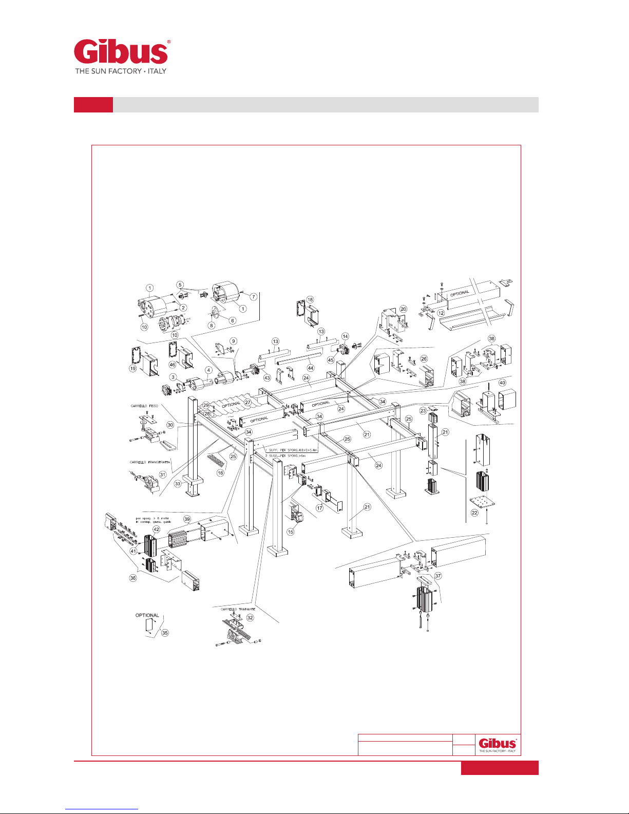
ESPLOSO COMMERCIALE MEDISOLAFLY R
(ISOLA 2 MODULI)
15-02-2016
DESCRIZIONE DATA:
00
REV:
Page 42 of 56
USE AND MAINTENANCE MANUAL
Code MUT 088
Rev. 1
MEDISOLAFLY R - ISLAND PLURI-MODULE
13.2
www.gibus.com

Page 43 of 56
USE AND MAINTENANCE MANUAL
Code MUT 088
Rev. 1
REF. ANN. DRAWING TITLE Q.TY
01
H10681 MOTOR TRANSMISSION SET MED 85-120 WHITE 1
02
A90710 TCEI M 6x16 STAINLESS STEEL SCREW 8
03
H24150015 TRANSMISSION SHAFT PROFILE MED 85-120 CM 15.3 GZ 2
04
H24140--- MOTOR SHAFT PROFILE D58-120 -
05
H10691 CAPS FOR TRANSMISSION SHAFT 85-120 WHITE 4
06
B6079# FLANGED BUSHING 1
07 B90320 TSPEI SCREW M 6x16 STAINLESS STEEL 2
08
A90060 NORMAL STAINLESS STEEL HEX NUT M 6 4
09 H16151 KIT BRACKETS FOR MOTOR SUPPORT OPEN FLY WHITE RAL 9010 1
10 SERV010 MOTORIZATION 1
11 A91110 TSPEI SCREW M 6x14 STAINLESS STEEL 2
12 H12101 TOP ROOF MOTOR PROTECTION MED ISOLA BI 13 H10720 JUNCTION F/DRIVING SHAFT MED 85 PM 14 H19102 BELT RETURN MED NYLON NE 2
15 H15642 RETURN TENSIONING BELT NYLON MED 130 NE 2
16 H41511 TOOTHED BELT T10-MED85-120 17 H16281 KIT FRONT CARTER VIVA WHITE RAL 9010 2
18 271634 REAR RIGHT CARTER SET FOR MEDISOLAFLY R 1
19 271635 REAR LEFT CARTER SET FOR MEDISOLAFLY R 1
20 271636 LATERAL COUPLING SER FOR MEDISOLAFLY R 4
21 H2493#--- ALU PR 70x130 MED SHARP EDGES 22 H13101 SELF LOAD BEARING FOOT 130 BI 4+2
23 H6102# ALUMINIUM FRONT FLAT CAP MED VIVA 4+2
24 H2505#--- LEG PROFILE MED 70X130 6 OGIVE 25 H2494#--- PR ALU GUIDE 70x130 ALU SINGLE SLOT MED 26 H16121 TOP EXT. KIT FOR CROSS BEAM OPEN FLY WHITE RAL 9010 2
27 SERV11 MED ROOF SHEETS 28 H37052 MED GASKET FOR ROOF/CANOPY FIXING SCREWS 29 R90343 SELF-TAPPING SCREWS TC + 4,2x32 C15 30 H10651 FIXED CARRIAGE MED85-120 WHITE 2
31 H10661 HORIZONTAL BAR CARRIAGE MED85-120 WHITE 2 x intermediary profiles
32 H10671 DRIVING CARRIAGE MED85-120 WHITE 2
33 H3792#
STAINLESS STEEL POST BASE PROTECTIVE COVER
FREESTANDING 130
4+2
34 H70191--- PVC PROF. TOP COVER MED LUCE WHITE RAL 9010 35 271637 ALUMINIUN CAPS SET FOR GUIDE MED VIVA optional
36 271638 JOINT SET FOR GUIDE WITH LEG MEDISOLAFLY R 2 with width > 600 cm
37 H13180 CORE 70x130 ISOLA GZ 2
38 H16161 UPPER CENTER SET FOR HORIZONTAL BEAM OPEN FLY PM 4+2
39 H13190 CORE PROFILE ELF LOAD BEARING BAR 130 GZ 2 with width > 600 cm
40 H13991 KIT SUPPORT FOR CENTRAL GUIDE 70X130 ISOLA 2 M WHITE 1
41 A90540 SCREW TSPEI M 8x20 INOX 4 with width > 600 cm
42 H37810 CORE 70 X 130 L=150 WITH 4 HOLES M8 RAW 2 with width > 600 cm
43 H24150030 TRANSMISSION SHAFT PR MED85-120 CM 30 GZ 1
44 H24150--- TRANSMISSION SHAFT PR MED85-120 45 H24150040 TRANSMISSION SHAFT PR MED85-120 CM 40 GZ 1
46 271639 REAR CENTER CARTER SET FOR MEDISOLAFLY 1
www.gibus.com
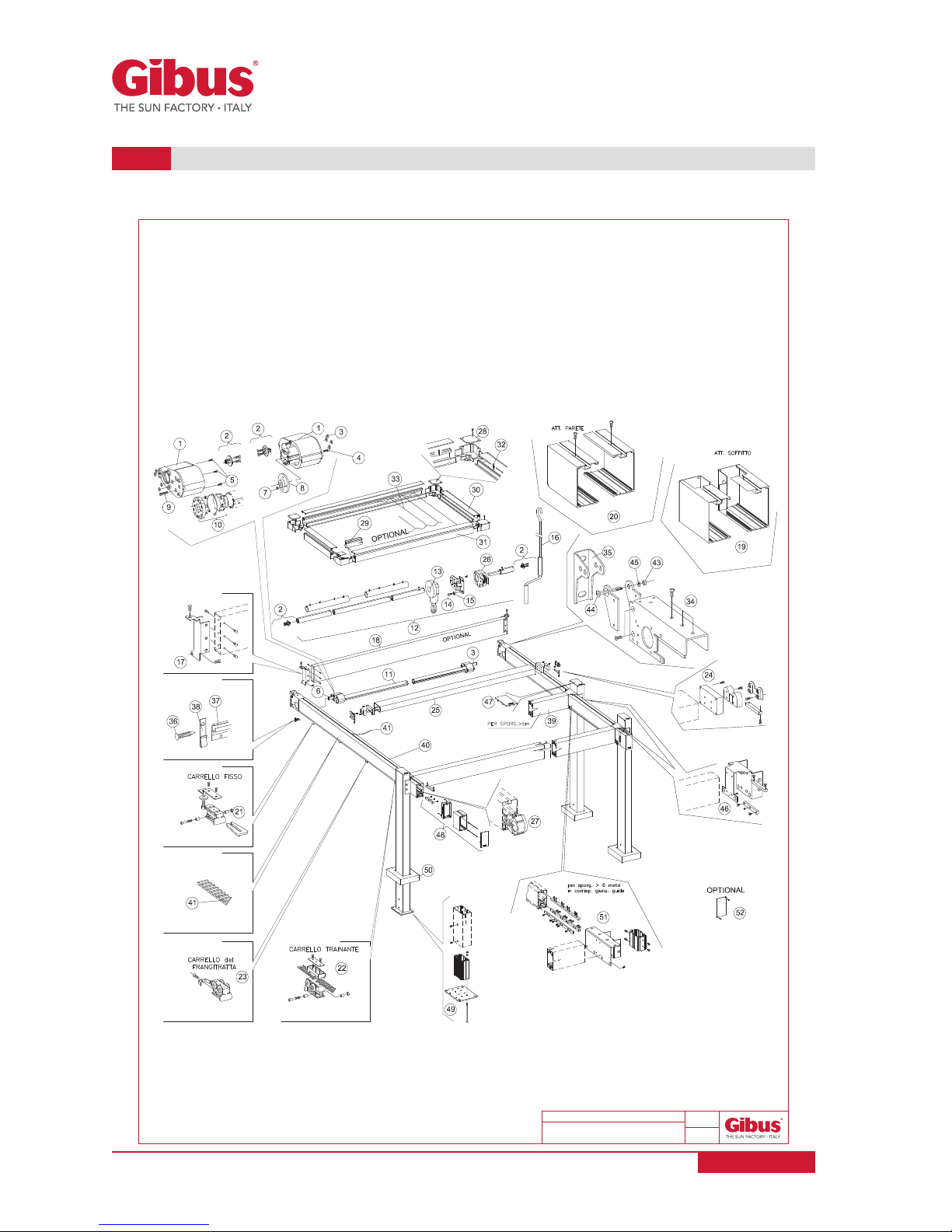
ESPLOSO COMMERCIALE MEDISOLAFLY R
(ADDOSSATA FRONTALE 1 MODULO)
15-02- 2016
DESCRIZIONE DATA:
00
REV:
Page 44 of 56
USE AND MAINTENANCE MANUAL
Code MUT 088
Rev. 1
MEDISOLAFLY R - FRONTAL LEANING VERSION SINGLE-MODULE
13.3
www.gibus.com
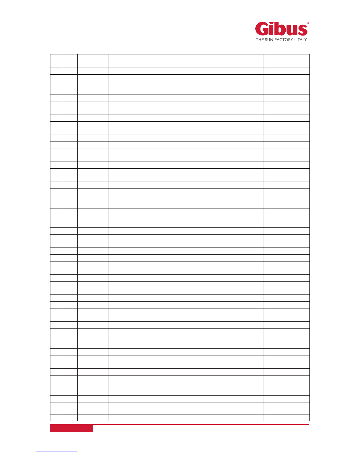
Page 45 of 56
USE AND MAINTENANCE MANUAL
Code MUT 088
Rev. 1
REF. ANN. DRAWING TITLE Q.TY
01
H10681 MOTOR TRANSMISSION SET MED 85-120 WHITE 1
02
H10691 CAPS FOR TRANSMISSION SHAFT 85-120 WHITE 4
03
A36850 SPACING RING FOR MOTOR SEGNO 8
04
B90320 TSPEI SCREW M 6x16 STAINLESS STEEL 2
05
A90880 SCREW TCEI M 6X20 INOX 8
06
H24150015 TRANSMISSION SHAFT PROFILE MED 85-120 CM 15.3 GZ 2
07 A90060 NORMAL STAINLESS STEEL HEX NUT M 6 4
08
B6079# FLANGED BUSHING 1
09 A91110 TSPEI SCREW M 6x14 STAINLESS STEEL 2
10 SERV010 MOTORIZATION 1
11 H24140--- MOTOR SHAFT PROFILE D58-120 12 H13360 GEARBOX TRANSMISSION MED UNICA 1
13 A4013# GEAR BOX 5:1 RAL 9010 1
14 A91190 SCREW TBEI Mx16 STAINLESS STEEL 2
15 B90430 RING SCREW D 8,4/14X1,6 STAINLESS STEEL 2
16 A4102#--- CRANK ROD 11 1
17 H15341 BRACKETS FOR REAR BEAM 100x30 MED LUCE WHITE RAL 9010 1
18 H2496#--- ROOF REAR SUPP. PROFILE MED LUCE CM 470 WHITE RAL 9010 19 H15381 BRACKETS CARTER FOR CEILING FIXING MED LUCE WHITE RAL 9010 1
20 H15401 BRACKETS CARTER FOR WALL FIXING WHITE RAL 9010 1
21 H10651 FIXED CARRIAGE MED85-120 WHITE 2
22 H10671 DRIVING CARRIAGE MED85-120 WHITE 2
23 H10661 HORIZONTAL BAR CARRIAGE MED85-120 WHITE
2 x intermediary
profiles
24 H11521 LATERAL JOINT WITH ADAPTER PR 70X130 RAL 9010 2
25 H2493#--- ALU PR 70x130 MED SHARP EDGES 26 H19102 BELT RETURN MED NYLON NE 2
27 H15642 RETURN TENSIONING BELT NYLON MED 130 NE 2
28 H11431 ANGULAR ROOF PR MED WHITE 4
29 R60262 BALLOON GASKET D. 5 30 H2448#--- ROOF COVER ALU PR MED CM 550 WHITE 31 H2447#--- ROOF ALU PROFILE MED CM 550 WHITE 32 C9005N SELF DRILLING SCREW TBC 3,9x16 ZI+NI 33 SERV11 MED ROOF SHEETS 34 H15330 BRACKETS KIT FOR WALL FIXING OF THE GUIDES MILL FINISHED 2
35 H3895# WALL/ CEIL. BRACKET STAINLESS STEEL MED LUCE WHITE RAL 9010 2
36 H90080 SELF- THREADNING TSP TORX 5,5x32 2
37 H2460#--- MONOGIVE W/ WING ALU PR 34x10 CM 600 WHITE 38 H37000 CLIP FRO MONOGIVE PROFILE 39 H2505#--- POST PROF. MED 70x130 6 GROOVES CM 500 WHITE RAL 9010 40 H2494#--- PR ALU GUIDE 70x130 ALU SINGLE SLOT MED 41 H41511 TOOTHED ROPE T10 42 H70191--- PVC PROF. TOP COVER MED LUCE WHITE RAL 9010 43 A90110 LOWER LOCK NUT M10 STAINLESS STEEL 2
44 H90380 SCREW TSPEI M10x70 STAINLESS STEEL 2
45 A90440 WASHER D 1,5/30x2 STAINLESS STEEL 2
46 271636 LATERAL COUPLING SER FOR MEDISOLAFLY R 2
47 H6102# ALUMINIUM FRONT FLAT CAP MED VIVA 2
48 H16281 KIT FRONT CARTER VIVA WHITE RAL 9010 2
49 H13101 SELF LOAD BEARING FOOT 130 BI 2
50 H3792# CARTER FOOT COVER ISOLA 130 WHITE 2
51 271638 JOINT SET FOR GUIDE WITH LEG MEDISOLAFLY R
2 with width >
600 cm
52 271637 ALUMINIUN CAPS SET FOR GUIDE MED VIVA optional
www.gibus.com
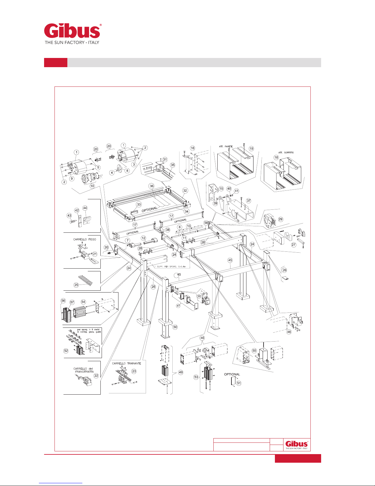
ESPLOSO COMMERCIALE MEDISOLAFLY R
(ADDOSSATA FRONTALE 2 MODULI)
15-02- 2016
DESCRIZIONE DATA:
00
REV:
Page 46 of 56
USE AND MAINTENANCE MANUAL
Code MUT 088
Rev. 1
MEDISOLAFLY R - FRONTAL LEANING VERSION PLURI-MODULE
13.4
www.gibus.com
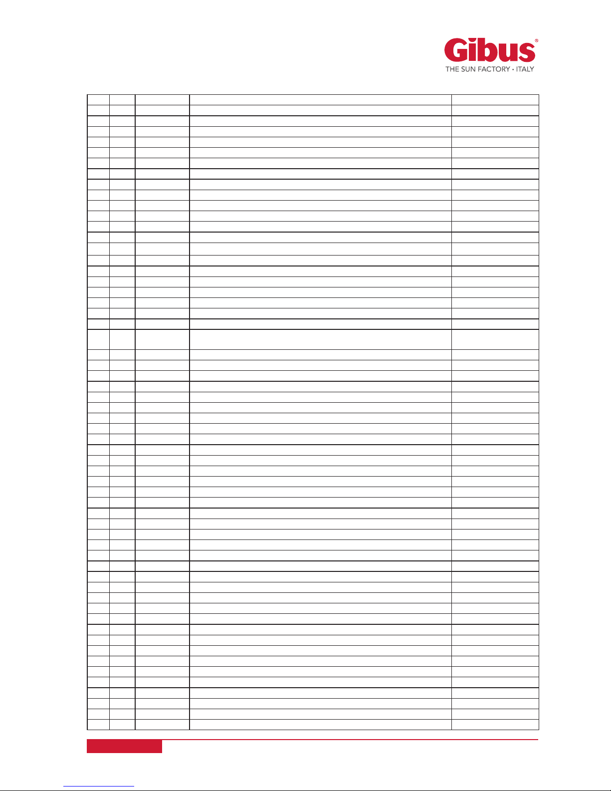
Page 47 of 56
USE AND MAINTENANCE MANUAL
Code MUT 088
Rev. 1
REF. ANN. DRAWING TITLE Q.TY
01
H1068# MOTOR TRANSMISSION SET MED 85-120 1
02
A36850 SPACING RING FOR MOTOR SEGNO 8
03
A91110 TSPEI SCREW M 6x14 STAINLESS STEEL 2
04
A90060 NORMAL STAINLESS STEEL HEX NUT M 6 4
05
A90880 SCREW TCEI M 6X20 INOX 8
06
H24150040 TRANSMISSION SHAFT PR MED85-120 CM 40 GZ 1
07 H24150015 TRANSMISSION SHAFT PR MED85-120 CM 15 GZ 1
08
B6079# FLANGED BUSHING 1
09 B90320 TSPEI SCREW M 6x16 STAINLESS STEEL 2
10 SERV010 MOTORIZATION 1
11 H10720 JUNCTION F/DRIVING SHAFT MED 85 PM 2
12 H24140--- MOTOR SHAFT PROFILE D58 MED85-120 13 H24150--- DRIVE SHAFT PROFILE D58 MED85-120 -
15 H3895# WALL/ CEIL. BRACKET STAINLESS STEEL MED LUCE WHITE RAL 9010 3
16 H15341 BRACKETS FOR REAR BEAM 100x30 MED LUCE WHITE RAL 9010 2
17 H2496#--- ROOF REAR SUPP. PROFILE MED LUCE CM 470 WHITE RAL 9010 18 H15381 BRACKETS CARTER FOR CEILING FIXING MED LUCE WHITE RAL 9010 1
19 H15401 BRACKETS CARTER FOR WALL FIXING WHITE RAL 9010 1
20 H10691 CAPS FOR TRANSMISSION SHAFT 85-120 WHITE 4
21 H10651 FIXED CARRIAGE MED85-120 WHITE 3
22 H10661 HORIZONTAL BAR CARRIAGE MED85-120 WHITE
3 x intermediary
profiles
23 H10671 DRIVING CARRIAGE MED85-120 WHITE 3
24 H7019#--- PVC PROF. TOP COVER MED LUCE 25 H41511 TOOTHED ROPE T10 26 H2494#--- PR ALU GUIDE 70x130 ALU SINGLE SLOT MED 27 H11521 LATERAL JOINT WITH ADAPTER PR 70X130 RAL 9010 4
28 H2493#--- ALU PR 70x130 MED SHARP EDGES 29 H19102 BELT RETURN MED NYLON NE 3
30 H15642 RETURN TENSIONING BELT NYLON MED 130 NE 3
31 H11431 ANGULAR ROOF PR MED WHITE 4
32 H2448#--- ROOF COVER ALU PR MED CM 550 WHITE 33 R60262 BALLOON GASKET D. 5 34 H2447#--- ROOF ALU PROFILE MED CM 550 WHITE 35 C9005N SELF DRILLING SCREW TBC 3,9x16 ZI+NI 36 SERV11 MED ROOF SHEETS 37 H15330 BRACKETS KIT FOR WALL FIXING OF THE GUIDES MILL FINISHED 3
38 H15391 CENTRAL COVER FOR WALL FIXING MED LUCE (2-3 MODULES) 1
39 H90380 SCREW TSPEI M10x70 STAINLESS STEEL 3
40 A90440 WASHER D 1,5/30x2 STAINLESS STEEL 3
41 A90110 LOWER LOCK NUT M10 STAINLESS STEEL 3
42 H37000 CLIP FRO MONOGIVE PROFILE 43 H90080 SELF- THREADNING TSP TORX 5,5x32 2
44 H2460#--- MONOGIVE W/ WING ALU PR 34x10 CM 600 WHITE 45 H2505#--- POST PROF. MED 70x130 6 GROOVES CM 500 WHITE RAL 9010 46 H16161 UPPER CENTER SET FOR HORIZONTAL BEAM OPEN FLY PM 2
47 H16281 KIT FRONT CARTER VIVA WHITE RAL 9010 3
48 271636 LATERAL COUPLING SER FOR MEDISOLAFLY R 4
49 H13101 SELF LOAD BEARING FOOT 130 BI 5
50 H3792# CARTER FOOT COVER ISOLA 130 WHITE 5
51 271637 ALUMINIUN CAPS SET FOR GUIDE MED VIVA optional
52 271638 JOINT SET FOR GUIDE WITH LEG MEDISOLAFLY R 2 with width > 600 cm
53 H13180 CORE 70x130 ISOLA GZ 1
54 H13190 CORE PROFILE ELF LOAD BEARING BAR 130 GZ 2
55 H13991 KIT SUPPORT FOR CENTRAL GUIDE 70X130 ISOLA 2 M WHITE 1
56 A90540 SCREW TSPEI M 8x20 INOX 4
57 H37810 CORE 70 X 130 L=150 WITH 4 HOLES M8 RAW 2
58 H24150030 TRANSMISSION SHAFT PR MED85-120 CM 30 GZ 1
www.gibus.com

ESPLOSO COMMERCIALE MEDISOLAFLY R
(ADDOSSATA LATERALE 1 MODULO)
15-02- 2016
DESCRIZIONE DATA:
00
REV:
Page 48 of 56
USE AND MAINTENANCE MANUAL
Code MUT 088
Rev. 1
MEDISOLAFLY R - LATERAL LEANING VERSION SINGLE-MODULE
13.5
www.gibus.com

Page 49 of 56
USE AND MAINTENANCE MANUAL
Code MUT 088
Rev. 1
REF. ANN. DRAWING TITLE Q.TY
01
H10681 MOTOR TRANSMISSION SET MED 85-120 WHITE 1
02
A90710 SCREW TCEI M 6X16 INOX 8
03
H24150015 TRANSMISSION SHAFT PR MED85-120 CM 15 GZ 2
04
H24140--- MOTOR SHAFT PROFILE D58 MED85-120 -
05
H10691 CAPS FOR TRANSMISSION SHAFT 85-120 WHITE 4
06
B6079# FLANGED BUSHING 1
07 B90320 TSPEI SCREW M 6x16 STAINLESS STEEL 2
08
A90060 NORMAL STAINLESS STEEL HEX NUT M 6 4
09 H16151 KIT BRACKETS FOR MOTOR SUPPORT OPEN FLY WHITE RAL 9010 1
10 SERV010 MOTORIZATION 1
11 A91110 TSPEI SCREW M 6x14 STAINLESS STEEL 2
12 H12101 TOP ROOF MOTOR PROTECTION MED ISOLA BI 13 H13151 TRANSMISSION KIT MED ISOLA ARG MM 1
14 H2416#--- TRANSMISSION JOINT PROFILE MED85-120 15 A4013# WINCH CH 5:1 CH BI 1
16 A4102#--- HOOK ROD 11 1
17 H19102 BELT RETURN MED NYLON NE 2
18 H15642 RETURN TENSIONING BELT NYLON MED 130 NE 2
19 H41511 TOOTHED ROPE T10 20 H16281 KIT FRONT CARTER VIVA WHITE RAL 9010 2
21 271634 REAR RIGHT CARTER SET FOR MEDISOLAFLY R 1
22 271635 REAR LEFT CARTER SET FOR MEDISOLAFLY R 1
23 271636 LATERAL COUPLING SER FOR MEDISOLAFLY R 4
24 H2493#--- ALU PR 70x130 MED SHARP EDGES 25 H13101 SELF LOAD BEARING FOOT 130 BI 4+2
26 H6102# ALUMINIUM FRONT FLAT CAP MED VIVA 4+2
27 H2505#--- POST PROF. MED 70x130 6 GROOVES 28 H2494#--- PR ALU GUIDE 70x130 ALU SINGLE SLOT MED 29 H16121 TOP EXT. KIT FOR CROSS BEAM OPEN FLY WHITE RAL 9010 2
30 SERV11 MED ROOF SHEETS 31 H37052 TOP ROOF FIXING RUBBER SCREW MED 32 R90343 SELF- THREADNING TC TORX 4,2x32 C15 INOX 33 H10651 FIXED CARRIAGE MED85-120 WHITE 2
34 H10661 HORIZONTAL BAR CARRIAGE MED85-120 WHITE 2 x intermediary profiles
35 H10671 DRIVING CARRIAGE MED85-120 WHITE 2
36 H3792# CARTER FOOT COVER ISOLA 130 WHITE 4+2
37 H70191--- PVC PROF. TOP COVER MED LUCE 38 271637 ALUMINIUN CAPS SET FOR GUIDE MED VIVA optional
39 271638 JOINT SET FOR GUIDE WITH LEG MEDISOLAFLY R 1 for width > 600 cm
40 H13871 WALL ANCHORING SETISOLA 130 BI 41 H13981 KIT CARTER SUPPORT MED ISOLA 130 WHITE 42 271640 WALL SIDE GUIDE JOINT SET FOR MEDISOLAFLY R 1 for width > 600 cm
43 H3791# CARTER CAP FLY ADD LAT SX 1
44 H3791# CARTER CAP FLY ADD LAT DX 1
45 H1269# CARTER FOR JOINT PART WITH ROOF FLY LEANING
46 H1270# CARTER FOR GUIDE PROTECTION FLY LEANING
www.gibus.com

FLY 1 MODULO
FLY 2 MODULI
Page 50 of 56
USE AND MAINTENANCE MANUAL
Code MUT 088
Rev. 1
FLY FABRIC COVER
13.6
www.gibus.com

Page 51 of 56
USE AND MAINTENANCE MANUAL
Code MUT 088
Rev. 1
FLY FABRIC COVER MEDISOLAFLY R - SINGLE-MODULE
REF. ANN. CODE TITLE Q.TY
90 H13522 MED clips clamp kit -
91 B49031 D3 Dyneema Pretens. p/Zerogr. cable -
97 H24210 - - - Alu Profile Breaker Pr. Light MED 85/120 -
98 H24590 - - - Pr Alu Tensioner MED FLY -
99 H13300 Cap-Casing p / Pr. Tensioner FLY -
100 H13310 Pin c / Spring p/ Pantograph FLY -
101 H13430 Cap c / Hinge p/Profile breaker Term FLY -
102 H13290 Cap c / Hinge p/Profile breaker Interm. FLY -
103 H37630 Stainless steel arm L = 354 MM p / FLY -
104 H91040 TC + 4.8x32 STAIN. STEEL self-tapping -
105 H36240 Platel c / Holes Fil. Clamp Med 85 -
106 A90780 M6x14 Stainless steel hex head screw -
107 B24581 Pr Front Cover Zerog BI -
108 A90630 D6,4/12,5x1,6 stainless steel washer -
109 H13411 Slide Side p/Wave fabric Cord. MED 85/120 -
FLY FABRIC COVER MEDISOLAFLY R - PLURI-MODULE
REF. ANN. CODE TITLE Q.TY
90 H13522 MED clips clamp kit -
91 B49031 D3 Dyneema Pretens. p/Zerogr. cable -
98 H24590 - - - Pr Alu Tensioner MED FLY -
104 H91040 TC + 4.8x32 STAIN. STEEL self-tapping -
105 H36240 Platel c / Holes Fil. Clamp Med 85 -
106 A90780 M6x14 Stainless steel hex head screw -
107 B24581 Pr Front Cover Zerog BI -
108 A90630 D6,4/12,5x1,6 stainless steel washer -
109 H13411 Slide Side p/Wave fabric Cord. MED 85/120 -
110 H24210 - - - Alu Profile Breaker Pr. Light MED 85/120 -
111 H13300 Cap-Casing p / Pr. Tensioner FLY -
112 H13310 Pantograph pivot with spring FLY -
113 H13430 Cap c / Hinge p/Profile breaker Term. FLY -
114 H13290 Cap c / Hinge p/Profile breaker Interm. FLY -
115 H37630 Stainless steel arm L = 354 MM p / FLY -
www.gibus.com

Page 52 of 56
USE AND MAINTENANCE MANUAL
Code MUT 088
Rev. 1
CHAPTER 14: TECHNICAL
DECLARATION OF INSTALLATION
14.1
DECLARATION OF INSTALLATION (to be filled by the installer)
Mod. Awning:
MEDISOLAFLY R
ISLAND
FRONTAL LEANING VERSION
LATERAL LEANING VERSION
WITH WINCH
WITH MOTOR
1 MODULE
2 MODULES
Size:
L:
S:
Fabric
Type:
Colour:
Engine
Type:
YES NO
Automatism
Type:
The undersigned: of the Company: Reference:
as: Address:
Declares under his sole responsibility
•ofhavingusedthecomponentscontainedinthepackagingoftheproductsbyGIBUSandadditionalproductsprovidedfor
by the Installation Instructions;
•ofhavingcheckedthetechnicalcomplianceofthehousingsite;
•ofhavingcarriedouttheinstallationthroughtheinstructionsprovidedbythemanufacturerintheUseandMaintenance
ManualandintheInstallationInstructionsdeliveredwiththepackagedproduct;
•ofhavingdeliveredtothecustomertheseUseandMaintenanceManualwiththeDeclarationofPerformanceDoPrelevant
to the regulations and European reference standards.
Installation:
Installation Notes:
date: Stamp and signature Gibus technician:
Mandatory maintenance within the end of the 2nd year date: Stamp and signature Gibus technician:
Mandatory maintenance within the end of the 3rd year date: Stamp and signature Gibus technician:
Mandatory maintenance within the end of the 4th year date: Stamp and signature Gibus technician:
Recommended maintenance within the end of the 5th year date: Stamp and signature Gibus technician:
IMPORTANT!: Extraordinary maintenance is compulsory and should be carried out by a Gibus specialized technician
by the end of the second year from the awning’s installation; this will extend the warranty up to the 3rd year from the
installation date. Use Gibus original spare parts to keep the warranty valid. Accordingly, a compulsory maintenance
operation within the end of the 3rd year from the installation date is to be required to the Gibus specialized technician
and that will extend the warranty to the 4th year; a compulsory maintenance in the 4th year from the installation date
will extend the warranty to the 5th year.
Mandatory Maintenance Notes:
www.gibus.com

Page 53 of 56
USE AND MAINTENANCE MANUAL
Code MUT 088
Rev. 1
Date Operation description
(including components replacement)
Full name and signature
specialized technician
NOTES:
MAINTENANCE AND NOTE REGISTER
14.2
www.gibus.com

Page 54 of 56
USE AND MAINTENANCE MANUAL
Code MUT 088
Rev. 1
PRODUCTION NOTES
14.3
FABRIC COVER
ASSEMBLED TO BE ASSEMBLED
TENSIONED LOOSEN
FABRIC
PVC Poly HR Opatex
PVC Precontraint 602
PVC Precontraint 302
SOLTIS 86
SOLTIS 92 shading
SOLTIS 96-W96
TS Light
TS Heavy
TS water-proof resin coated
TS FR fireproof
Acrylic
Liberty Acrylic
Printed Acrylic
Other
PAINTING
Guide bearing profiles
Brackets – Feet – Castings
Plastic Notched sheet roof
Standard
production
White RAL 9010 White White RAL 9010
Ivory RAL 1013 Ivory Ivory RAL 1013
VR Light steel Light steel Metallized RAL 9006
Anthracite VIV 416 Anthracite Anthracite RAL 7016
Upon
request
Brown RAL 8017 Anthracite Brown RAL 8019
Bronze Anthracite Brown RAL 8019
Anthracite RAL 7016 Semigloss Anthracite Anthracite RAL 7016
Corten Anthracite Brown RAL 8019
other
..............................................
other
....................
other
............................
Profile breaker
Standard
production
RAL 9010 white on white PVC RAL 1013 beige on champagne PVC
RAL 1013 beige on champagne PVC Bordeaux/champagne
Green/champagne Grey/champagne
Anthracite/champagne
Upon request
Anthracite VIV 416 VR Light steel
Anthracite/champagne
AWNING VERSION
ISLAND
FRONTAL LEANING VERSION
LATERAL LEANING VERSION
1 MODULE
WINCH
MOTOR
2 MODULES
WINCH
MOTOR
www.gibus.com

ANNEX 0 - EC MARKING
ANNEX 1 - SELF-CERTIFICATION DOCUMENT (*)
CHAPTER 15: ANNEXES
(*) IMPORTANT NOTE: the stated performance is only guaranteed if the installation of the product is carried
out correctly by the authorized dealer. The latter is required to compile the “DECLARATION OF CORRECT
INSTALLATION”, which should be left with the final customer when installation is completed.
Via Einaudi, 35 - 35030 Saccolongo (PD)
PERFORMANCE DECLARATION no: MUT 088-CPR-2016-06-30
The performance of the unit given in the items 1 and 2 complies with the performance
declared in the item 9. This performance declaration is issued under the manufacturer’s
sole responsibility as per item 4.
Saccolongo, 15/06/2016
Signed in the name of and on behalf of:
Gianfranco Bellin
Chief Executive Ofcer
Gibus S.p.A. - Via Einaudi, 35 - 35030 Saccolongo
www.gibus.it - E-mail: gibus@gibus.it
Unique identication code for the product-type: Gibus
®
mod. MEDISOLAFLY R
1.
Designed use:
“Pergola type” folding awning for outside use
3.
Name and address of the manufacturer:
4.
Serial number: see the HOLOGRAM on the back cover
2.
Assessment and check system of constant performance: System 4
6.
10.
Performance declared in accordance with the UNI EN 13561 harmonized standard:
9.
16
UNI EN 13561
Declaration of Performance no:
“Pergola type” folding awning for outside use
MODEL: Gibus® mod. MEDISOLAFLY R
Wind resistance:
Total solar energy transmittance g
tot
:
MUT 088-CPR-2016-06-30
Technical class 3
see prod. specifications Back of cover
Essential Characteristics Declared performance
Wind resistance Class 3
Solar factor g
tot
See the value in the product specications on the back cover (**)
class 0 1 2 3 4
according to EN 14501 g
tot
g
tot
>= 0,50 0,35 <=g
tot
< 0,50
0,15 <=g
tot
< 0,35
0,10 <=g
tot
<0,15
g
tot
<=0,1
HOLOGRAM
(**) g
tot
value referring to the indicated fabric awning positioned vertically in front of a glass window. The value corresponding
to the specic application must be determined by taking all the specications of the housing unit and the inclination of the
fabric into account. The g
tot
Class can be found in the corresponding table on the previous page.
Gibus S.p.A.
Via Luigi Einaudi, 35
35030 Saccolongo (PD) - ITALY
www.gibus.it - gibus@gibus.it
 Loading...