

Gibertini densimat Instruction Manual

INSTRUCTION MANUAL
INSTRUCTION MANUAL
INSTRUCTION MANUAL
INSTRUCTION MANUAL
INSTRUCTION MANUAL
INSTRUCTION MANUAL
INSTRUCTION MANUAL
INSTRUCTION MANUAL
INSTRUCTION MANUAL
INSTRUCTION MANUAL
INSTRUCTION MANUAL
INSTRUCTION MANUAL
INSTRUCTION MANUAL
INSTRUCTION MANUAL
INSTRUCTION MANUAL
INSTRUCTION MANUAL
INSTRUCTION MANUAL
INSTRUCTION MANUAL
INSTRUCTION MANUAL
INSTRUCTION MANUAL
INSTRUCTION MANUAL
INSTRUCTION MANUAL
INSTRUCTION MANUAL
INSTRUCTION MANUAL
INSTRUCTION MANUAL
INSTRUCTION MANUAL
INSTRUCTION MANUAL
INSTRUCTION MANUAL
DensiMat
Hydrostatic Balance

60.50.375 Ed. 2 - June 2009
All rights reserved.
Forbidden any form of print, duplication, reproduction and publication
of this instructions, or part of it, without the written agreement of
GIBERTINI ELETT R ONICA Srl
INDEX
1. IMPORTANT WARNINGS.................................................................................................3
2. GENERAL DESCRIPTION AND TECHNICAL CHARACTERISTICS................................4
3. INSTALLATION.................................................................................................................5
3.1 PROCEDURE INSTALLATION..........................................................................................5
3.2 DENSIMAT KE YBOARD....................................................................................................7
4. MEASUREMENTS WITH DENSIMAT...............................................................................7
4.1 DETERMINATION OF SPECIFIC GRAVITY D
20/20
OF A LIQUID...................................8
4.2 DETERMINATION OF THE DENSITY OF A LIQUID AT 20°C...........................................9
4.3 COMPENSATION OF FLOATER IN USE........................................................................10
5. BEHAVIOUR OF THE INSTRUMENT WHE N SWITCHING ON AND CONDITIONS FOR
OPTIMAL MEASUREMENTS.........................................................................................11
6. APPENDIX A: LIST OF PRINCIPAL MESSAGES DISPLAYED .....................................13
7. APPENDIX B: POSSIBLE OPTIONS FROM DENSIMAT KEYBOARD...........................14
8. APPENDIX C: USE OF THE CYLINDER FO R ME ASURE ME NTS IN CONTINUOUS ....15
8.1 INSTALLATION...............................................................................................................15
8.2 OPERATING INSTRUCTION...........................................................................................16
9. APPENDIX D: REFERENCE TO LEGAL METROLOGY.................................................17
9.1 METROLOGICAL CHECKING OF DENSIMAT................................................................17
10. DISPOSAL – INFORMATION FOR USERS....................................................................19
DensiMat
ENGLISH
- 3 -
- ATTENTION -
READ CAREFULLY THIS MANUAL, WHICH IS INTEGRAL PART OF THE
INSTRUMENT, BEFORE INSTALLING THE BALANCE
1. IMPORTANT WARNINGS
N.B. - These "WARNINGS" are integral part of the instrument
This instrument is to be used strictly for scientific purposes and/or for internal factory control only.
The use of our instruments is forbidden in the cases provided by art. 1, point 2, letter a) of directive
90/384, except for those models approved with CE mark (legal metrology).
THIS INSTRUMENT IS NOT T O BE USED IN AREAS EXISTING DANGER OF EXPLOSION.
It is important to note the following points for correct operation of the instrument:
1. Read the technical instructions given in the operating manual carefully. This manual contains information
about installation and use. If these instructions are not carried out precisely, the accuracy of results may be
affected. If in doubt, please consult the supplier’s engineers.
2. In common with any electrical equipment, installation should be carried out by a competent person. In
particular:
- ensure that the instrument is correctly earthed;
- do not install the instrument in areas of high fire risk, for example, in the presence of inflammable gases
and vapours;
- switch off and disconnect the power supply before removing any cover;
- do not touch the instrument with wet hands.
3. Install the instrument on a vibration free base and away from draughts or sources of heat. Check the
instrument with test weighing after installation or after repositioning.
4. Avoid connection to a power supply showing high voltage variations due to other loads. The instrument
should not be connected to the same electrical circuit as other high power consuming equipment as large
fluctuations may cause some inaccuracy.
5. The instrument should be checked every 6 months for correct functioning, calibration and accuracy of the
internal calibration mass by a suitable qualified person.
6. A routine calibration check should be carried out each day before use, using a standard mass. This mass
should be independently checked monthly.
7. Check the zero function before each weighing operation.
8. If in doubt about any function please call a qualified person. Avoid interference by non-qualified persons.
9. If the instrument is used for weighing food or drink, ensure that other substances are not weighed on the
unit which might cause contamination.
10. If the instrument is used for weighing chemicals and other similar substances ensure that it is cleaned and
any spillage removed to avoid potentially dangerous reactions.
11. Always clean the instrument after use to avoid subsequent inaccuracies and/or damage to the equipment.
12. Gibertini Elettronica s.r.l. does not accept any legal liability for damages or other consequences due to
mishandling of the instrument or its accessories.
ADDITIONAL PROCEDURES FOR WEIGHING SUBSTANCE WITH GREAT ACCURACY
Gibertini Instruments are manufactured to be reliable in use with high accuracy. However, reduced accuracy is
always possible due to ambient conditions, incorrect installation or improper use. Where greater accuracy is
required, the following procedures should be observed:
- use modern instruments (manufactured within three years) which are fully maintained;
- use certified calibration masses before each weighing operation;
- make at least two measurements;
- install the instrument in a draught-free, constant temperature cabinet: consider the use of two
instruments installed together and make weighings on both units, otherwise use calibrated masses with
a certificate of calibration from a recognised institute.
ALL ELECTRON IC BALANCES, WHICH ARE SENSITIVE TO CHANGES O F GRAVITY, MUST BE
CHECKED AND CALIBRATED IN THE PLACE WHERE THEY ARE TO BE USED (EEC 90/384).
ALL OUR INSTRUMENTS MEET INTERNATIONAL EMC-EMI-RFI STANDARDS ACCORDING TO 2004/108
EEC DIRECTIVE ON ELECTROMAGNETIC COMPATIBILITY.
ENGLISH
DensiMat
- 4 -
2. GENERAL DESCRIPTION AND TECHNICAL CHARACTERISTICS
The instrument consists of an electronic hydrostatic balance DENSIMAT, with a
sensitivity of fifth decimal points.
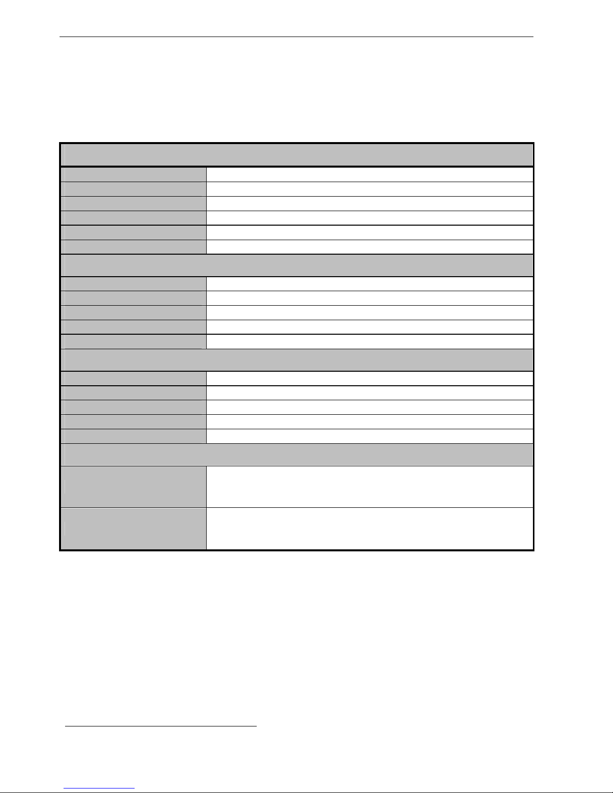
GENERAL SPECIFICATIONS
Warm-up time
≥ 15 minutes
Operating temperature
+15°C / +30°C
Data output
RS232 I/O
Operating voltage
220 V - 15% / + 10 % (110 V optional)
Power consumption
10 VA
Dimensions and weight
210x355x360 mm - 7,5 kg ~
HYDROSTATIC BALANCE SECTION
Relative density
Measuring range: 0.5 - 2.25
Readability
0.00005
Repeatability
+/- 0.00005
Auto-calibration
With internal mass
Response time
6 sec.
THERMOMETER SECTION
Measuring temperature
Range 8 ÷ 32 °C
Sensitivity
0.025 °C
Readability
0.1 °C
Repeatability
+/- 0.05 °C (range 10 ÷30 °C)
Thermometric probe
Pt 100 1/3 DIN
EQUIPMENT
Standard
2 floaters (plungers) calibrated
for weight (50 g) and volume (20 ml)
2 double wall 70 ml cylinders - Power supply
On request
Cylinder for measurements in continuous
Pan for metrological control
Certificated masses - Certificated floaters
FLOATERS INTERCHANGEABLE IN MASS AND VOLUME
Particular care must be paid in the construction and calibration of floaters.
They are all interchangeable in mass and in volume in order to facilitate utilization; for
example to determine the specific gravity of a must or a given wine and the relative
ASV, 2 separate floaters can be used without problem to avoid contamination
(preliminary check of the compensation factor; see chapter 4.3).
To obtain the above both the suspension
1
wire and the surface of the glass have been
subject of many studies in order to resolve the problems caused by surface tension,
from the volume of wire and from electrostatic charges.
1
Realized with an antimagnetic material, inoxidizable and a diameter lower or equal of 0,20 mm
DensiMat
ENGLISH
- 5 -
The wire is made with an antimagnetic material, inoxidizable and a diameter lower or
equal of to 0,20 mm.
The volume of floaters, on request, can be certified by the competent European
Institutes such as the L.N.E. of Paris, the I.M.G.C. of Turin, the PTB in Germany etc.
3. INSTALLATION
Densimat was designed and made to resist and to function even under difficult
conditions. However, it is advisable to install Densimat:
on a rigid support without vibrations
in a stable room temperature and without excessive ventilation
utilizing a separate electrical supply.
NOTE: if the Densimat stops working because of an incorrect operation on the
keyboard, the plug must be removed and connected again to the socket while
pressing the " + " key. When the instrument is switched on again the following
message appears
P n o r
which indicates the return to use of the parameters of standard functioning.
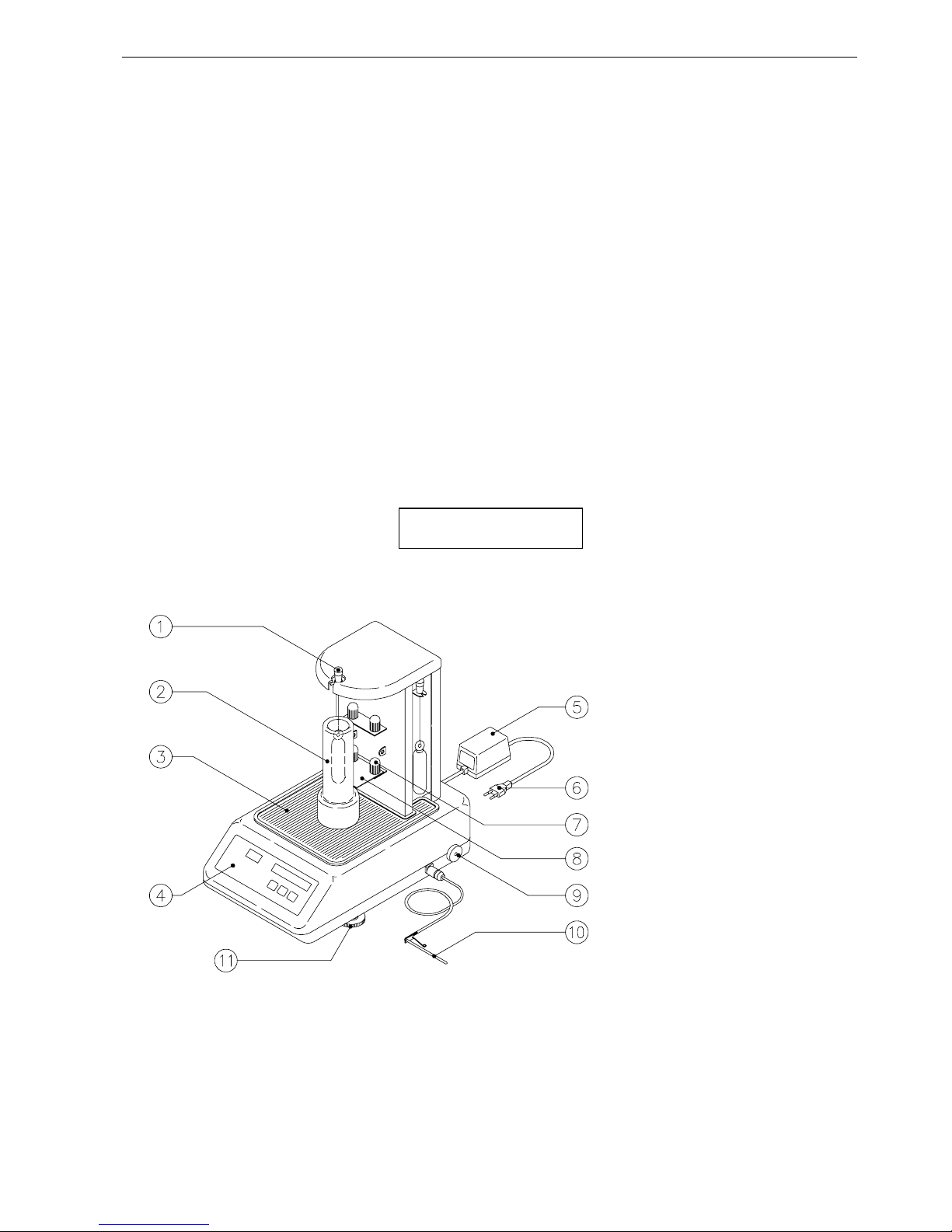
1- Floater knob
2- Cylinder and floater
3- Rubber mat
4- Keyboard
5- Transformer
6- Plug
7- Knob to adjust the
cylinder-balance
8- Centering plate
9- Knob for blocking
balance (to transport)
10- Thermo probe
11- Levelling feet
Figure 1
3.1 PROCEDURE INSTALLATION
Level the balance by adjusting the back supports in order to centre the air bubble in
the middle of the circle.
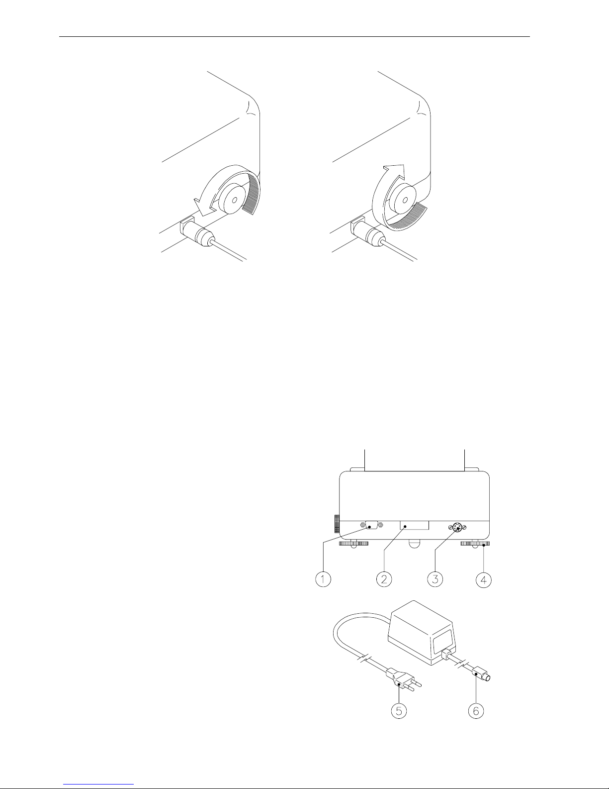
unlock the balance by rotating the knob in an anticlockwise direction and when it
stops it comes to rest on the right side of the instrument (Fig. 1 n. 9 and Fig. 2).
ENGLISH
DensiMat
- 6 -
UNLOCKED LOCKED ( Only to transport )
Figure 2
Insert the connector of the thermo probe in the place indicated in figure 1 (n. 10),
keeping the locking pin in an upright position and pushing it till its complete
insertion: the connector is in the correct position if, trying to pull it out, it does not
come. To pull it out press the locking pin.
Connect the circular socket of the transformer (fig. 3 n. 6) to the connector of
Densimat (fig. 3 n. 3) keeping the flat side of pin upwards. Connect the transformer
to the socket (fig. 3 n. 5) of the electric mains.
Figure 3
Rear view of DENSIMAT
1- RS323 serial connection
2- Serial number
3- Transformer socket
4- Adjustable supports
5- Mains plug
6- Transformer plug
 Loading...