

Giatec Scientific iCOR User Manual

USER MANUAL
iCOR
®
C O N N E C T I O N L E S S C O R R O S I O N R A T E
M E A S U R E M E N T D E V I C E F O R
R E I N F O R C E D C O N C R E T E S T R U C T U R E S
Smart Concrete Testing Technologies
™


iCOR® User Manual
© Giatec Scientific Inc. i
TA BLE O F C ON T EN T S
TABLE OF CONTENTS .............................................................................. I
PACKAGE CONTENTS ............................................................................ III
WARRANTY ................................................................................................. V
SAFETY INSTRUCTIONS ........................................................................... 1
SAFETY SYMBOLS .............................................................................................................. 1
GENERAL GUIDELINES ................................................................................................... 1
DEVICE HANDLING ......................................................................................................... 2
DEVICE OPERATION ........................................................................................................ 2
DEVICE CLEANING .......................................................................................................... 3
OPERATION ENVIRONMENT .......................................................................................... 3
STORAGE ENVIRONMENT ............................................................................................... 3
INTRODUCTION TO GIATEC ICOR® ...................................................... 4
CORROSION OF STEEL IN CONCRETE ........................................................................... 5
CORROSION RATE MEASUREMENT ............................................................................... 5
POLARIZATION RESISTANCE OF REBAR (RP) ............................................................... 7
ELECTRICAL RESISTIVITY OF CONCRETE .................................................................... 8
HALF-CELL POTENTIAL MEASUREMENT ..................................................................... 8
APPLICATION ..................................................................................................................... 9
COMPLICATIONS/ LIMITATIONS .................................................................................. 10
ICOR® OVERVIEW ..................................................................................... 12
ICOR® MEASUREMENT UNIT OVERVIEW ................................................................. 12
ICOR® OPERATION .................................................................................. 15
PREPARATION OF ELECTRODES .................................................................................. 15
TURNING ON THE ICOR® ............................................................................................ 16
LED INDICATOR............................................................................................................. 16

iCOR® User Manual
© Giatec Scientific Inc. ii
CHARGING THE ICOR® ................................................................................................. 17
TURNING OFF AND ON THE DEVICE ....................................................................... 18
STORING THE DEVICE ................................................................................................... 18
DATA RECORDING AND PROCESSING SETUP .................................. 19
TABLET SOFTWARE ........................................................................................................ 19
ERRORS ............................................................................................................................. 33
CONTOUR PLOTS ............................................................................................................ 38
DATA EXPORTING AND SHARING .............................................................................. 40
VERIFICATION ......................................................................................... 44
DEVICE VERIFICATION .................................................................................................. 44
LOG FILE .......................................................................................................................... 48
PRACTICAL CONSIDERATIONS ............................................................ 48
MAINTENANCE ........................................................................................ 50
SERVICE ............................................................................................................................ 50
REPLACEMENTS............................................................................................................... 50
GIATEC ICOR® TECHNICAL SPECIFICATIONS ................................. 51
GENERAL.......................................................................................................................... 51
OPERATING CONDITIONS ............................................................................................. 51
REFERENCES ............................................................................................ 52
TERMS AND CONDITIONS OF SALE ("SALE AGREEMENT") ........ 53
EX HIB IT A: EN D U S ER S OF T WA R E L IC E NS E ...................... 60

iCOR® User Manual
© Giatec Scientific Inc. iii
PA CK A G E C O NT E NT S
Part
Qty
Photo
iCOR® Measuring Device
1X
Measurement Cable
(for half-cell test)
1X
Charging Cable
1X
Charger Cable for Tablet
1X
Contact Sponge
(for half-cell electrode)
3X
Alligator Test clip
1x
Contact Sponge
(for corrosion electrodes)
12X
Electrode Storage Solution
1X
iCOR® User Manual
© Giatec Scientific Inc. iv
Conductive gel
1X
Spray Bottle
1X
Carrying Case
1X
Data Recording App
-
Tablet with hands-free
carrying support
1X
Tablet Charger
1X
Verification Kit
(for half-cell potential)
1X
Verification Kit
(for corrosion rate/electrical
resistivity)
1X
* Please note that the images above are for illustration purpose only and might
not be to scale.

iCOR® User Manual
© Giatec Scientific Inc. v
WA RR A NT Y
LIMITED WARRANTIES
Giatec warrants the Product against defects in materials and workmanship
under normal use (the “Warranty”) for a period of 12 months from the
Delivery Date (the “Warranty Period”), on the condition that the Product
has been completely paid for. Unless as otherwise mandated by local law, the
Warranty Period does not restart if Customer receives a replacement
appliance and/or replacement Software. This Warranty does not apply: (a) to
consumable parts, such as batteries and cables unless damage has occurred
due to a defect in materials or workmanship; (b) to cosmetic damage,
including but not limited to scratches, dents and broken plastic on ports; (c)
to damage caused by accident, abuse, misuse, neglect or failure to properly
maintain (to include but not limited to water damage and/or condensation
or improper temperatures during storage), or improper installation; (d) to
damage caused by electrical disturbances or acts of God, to include but not
limited to civil disturbance, war, flood, fire, rodents or insects; (e) where
manufacturer’s serial numbers and security labels have been removed from
the Product; and (f) to damage caused during shipment (due to Customer’s
improper packaging) from Customer to Giatec in the case of Product returns
for repair.
Giatec disclaims all other warranties, express or implied, including without
limitation implied warranties of merchantability, fitness for a particular
purpose, or against hidden or latent defects. Giatec’s responsibility for
warranty claims is limited to repair or replacement. Giatec reserves the right
to modify this Warranty at any time, at its sole discretion, and with notice to
Customer.
Giatec does not warrant that the operation of the Product will be
uninterrupted or error-free. Giatec is not responsible for damage arising from
failure to follow instructions relating to the Product’s use. This Warranty is
voided immediately if repair, modification (to include upgrades, expansions
or usage or addition of non-manufacturer parts or accessories), alteration or

iCOR® User Manual
© Giatec Scientific Inc. vi
other service is attempted other than by Giatec. In this regard, the integrity
of the appliance casing (aka the box) should not be violated for any reason,
unless expressly authorized by Giatec in writing.
THE WARRANTY SET FORTH IS EXCLUSIVE AND NO OTHER
WARRANTY, WHETHER WRITTEN OR ORAL, IS EXPRESSED OR
IMPLIED. GIATEC SCIENTIFIC INC. SPECIFICALLY DISCLAIMS
THE IMPLIED WARRANTIES OF MERCHANTABILITY AND
FITNESS FOR A PARTICULAR PURPOSE.
* Please refer to the complete Terms and Conditions of Giatec’s products for
more details.
* The information contained in this document is subject to change without
notice.

iCOR® User Manual
© Giatec Scientific Inc. 1
SA FE T Y I N S TR U C T IO N S
This chapter contains important safety instructions that the user must follow
to operate and store the Giatec iCOR® device. Read the following safety
information before any operation to ensure your safety and to keep the device
in good working condition. Keep this user manual in a safe place for future
reference.
SAFETY SYMBOLS
In order to ensure the safety of the operator and increase the service life of
the instruments, pay attention to safety precautions described in this manual.
These messages are indicated by a symbol throughout this user manual.
WARNING: Identifies conditions or practices that could result
in injury or loss of life.
CAUTION: Identifies conditions or practices that could result
in damage to Giatec iCOR® or to other properties.
ATTENTION: Refer to the User Manual
NOTES: Identifies important points related to the operation
of the device
GENERAL GUIDELINES
1. Always follow basic safety precautions when using this product to
reduce risk of injury from fire or electric shock.
2. Read and understand all instructions in the documentation that
comes with Giatec iCOR®.
3. Observe all warnings and instructions marked on the product.
iCOR® User Manual
© Giatec Scientific Inc. 2
DEVICE HANDLING
CAUTION
• Giatec iCOR
®
is a non-destructive testing device. The electronic
parts, corrosion measurement electrodes, and half-cell potential
electrode are sensitive components. Please handle them with care.
• Do not place any heavy objects on the iCOR
®
device or the tablet.
• Avoid severe impact or rough handling that leads to damaging
iCOR® or the tablet.
• Do not disassemble iCOR
®
.
• Store the product in a protected location (e.g. carrying case) where
no one can step on or trip over the connection and USB-charging
cables, and in a location where these cables cannot be damaged.
DEVICE OPERATION
WARNING
• Power Input: USB only.
• Only use the provided USB charging cable for iCOR®, and the
provided power adapter for the tablet.
• Do not perform measurements at the circuits directly connected to
Mains (Live circuit).
• Do not place the instrument in a place where there is a chance of
spilling liquids on the device.
iCOR® User Manual
© Giatec Scientific Inc. 3
DEVICE CLEANING
ATTENTION
• Disconnect the device from the cable after testing (in case of half-
cell measurement).
• Do not use chemicals or cleaners containing harsh products such as
benzene, toluene, xylene, and acetone.
• Do not submerge the iCOR
®
device or the operating tablet
OPERATION ENVIRONMENT
ATTENTION
• Location: Indoor/outdoor
• Relative Humidity: 20% to 90%
• Temperature: 0°C to 45°C
• Avoid direct sunlight
• Do not submerge the device
STORAGE ENVIRONMENT
ATTENTION
• Location: Indoor
• Relative Humidity: 5% to 90%
• Temperature: 0°C to 50°C
iCOR® User Manual
© Giatec Scientific Inc. 4
IN T R OD U CT I ON T O G I A T E C i C O R®
Giatec iCOR® is a compact and comprehensive non-destructive testing
(NDT) device for corrosion evaluation of reinforced concrete structures.
iCOR® can be used in field applications (i.e., condition assessment) as well as
laboratory testing.
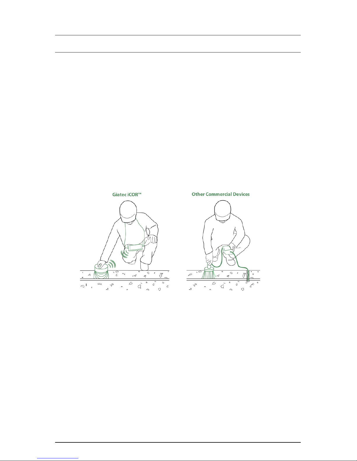
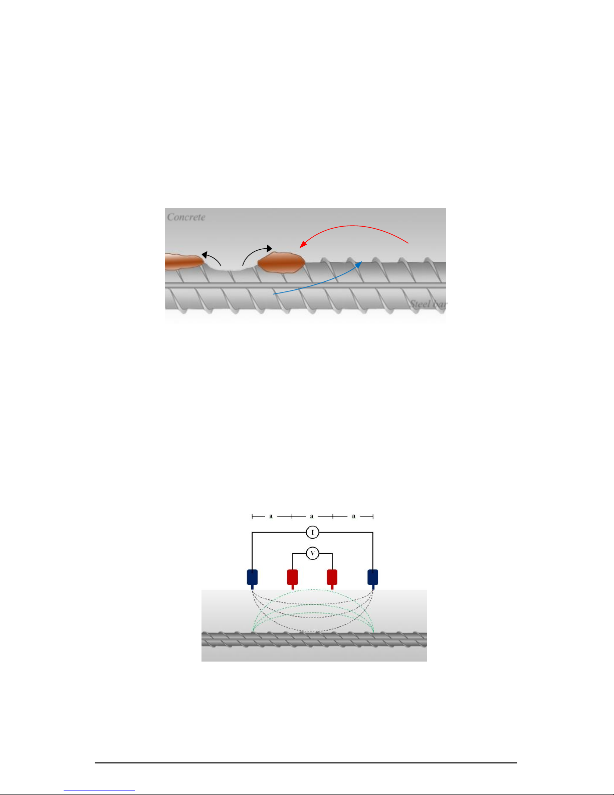
iCOR® benefits from a patented technology that makes it possible to estimate
the corrosion rate of rebar through a non-invasive approach. This means that
the need to connect the measuring unit to the rebar (which is the case for
other commercial devices) is eliminated in iCOR®. Fig. 1 schematically
illustrates the non-invasive feature of iCOR® compared to other
conventional corrosion testing devices.
Figure 1. Comparison of the iCOR
®
device vs other conventional
devices
Giatec iCOR® is also equipped with high precision sensors to measure the
electrical resistivity of concrete, the half-cell potential, ambient temperature
and relative humidity. iCOR® benefits from a wireless capability to transmit
data to a tablet, where data can be stored, analyzed and visualized. Moreover,
the tablet app offers a powerful post-processing tool and an easy way to share
the results with other team members. iCOR® can significantly save time,
human resources and cost.
iCOR® User Manual
© Giatec Scientific Inc. 5
CORROSION OF STEEL IN CONCRETE
The corrosion of steel reinforcement inside concrete can be described as an
electrochemical reaction. In this reaction, electrons migrate from the anodic
zone to the cathodic zone, releasing ferrous ions at the anode and hydroxide
ions at the cathode (Fig. 2). This will eventually lead to a potential difference
between the anodic and cathodic areas at the surface of the steel
reinforcement.
Figure 2. Corrosion of steel in concrete
CORROSION RATE MEASUREMENT
Measurement Concept
The electrical response of rebar inside the concrete can be determined from
the surface of concrete with four electrodes as shown in the Fig. 3. A constant
AC current is applied between the outer electrodes and the voltage between
the inner electrodes is measured.
Figure 3. The configuration of 4 electrodes on the surface of concrete
for corrosion detection of rebar inside the concrete
2Fe(OH)2
Steel bar
Concrete
4e-
O2 +2H2O +4e-→4OH-
Cathode
2Fe2+
2Fe→2Fe2+ + 4e-
Anode
4OH-
iCOR® User Manual
© Giatec Scientific Inc. 6
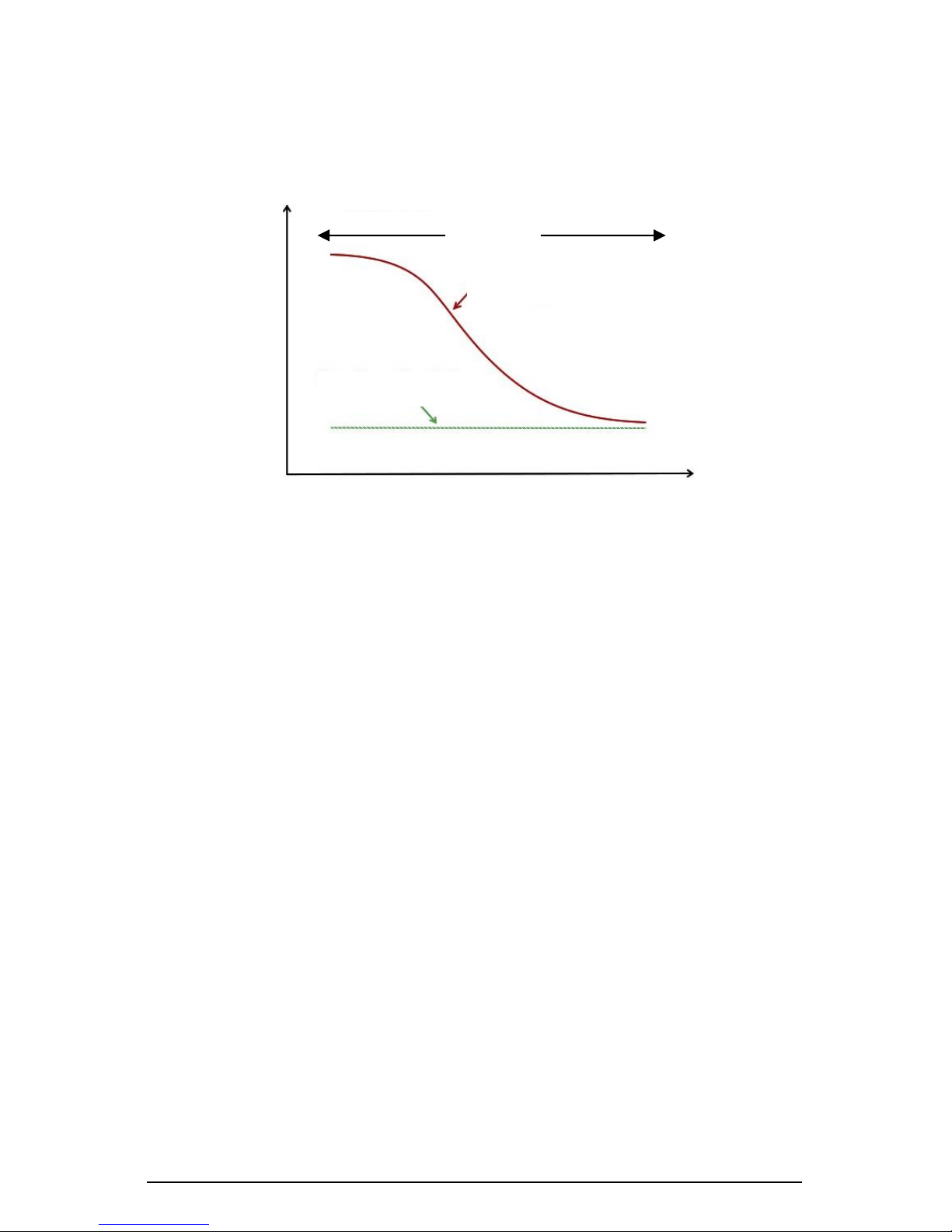
By sweeping the frequency of the AC current from a low frequency to a high
frequency, the voltage of the system is recorded as illustrated schematically
in Fig. 4.
Figure 4. The schematic illustration of the voltage-frequency response of
the corroding rebar compared to the non-corroding rebar
The voltage response of a corroding rebar is different from that of a noncorroding rebar. The voltage of a non-corroding rebar increases in the low
frequency zone of the plot, but it is almost invariable for a corroding rebar.
The basis of this concept has been utilized in iCOR® technology to detect
the corroding areas of reinforced concrete structures from the surface of
concrete. This technology eliminates the need to have an electrical
connection to the rebar inside the concrete unlike other existing nondestructive corrosion measurement techniques.
iCOR® Measurement Technique
As mentioned above, the low-frequency impedance response of rebar in
concrete can be correlated to the corrosion state of reinforcement in
concrete. However, direct measurement of the low-frequency impedance of
rebar in concrete is very time-consuming and vulnerable to noise
interruption; hence, it is not practical to use this technique in the field to
measure the corrosion rate of rebar inside the concrete. In Giatec iCOR®,
the low-frequency behavior of reinforced concrete system is determined by
applying a narrow DC/AC current pulse or a DC/AC step voltage for a short
Frequency (Hz)
Voltage (V)
Non-corroding bar
Corroding bar
High frequency
Low frequency
iCOR® User Manual
© Giatec Scientific Inc. 7
period of time and simultaneously recording the voltage of the system with a
relatively high sampling rate. Using the recorded voltage and the applied
current, the low-frequency impedance response of rebar in concrete can be
extracted which can be used to determine the state of corrosion in reinforced
concrete structures. This patented technology has been developed by Giatec
Scientific Inc. and is called Connectionless Electrical Pulse Response Analysis
(CEPRA).
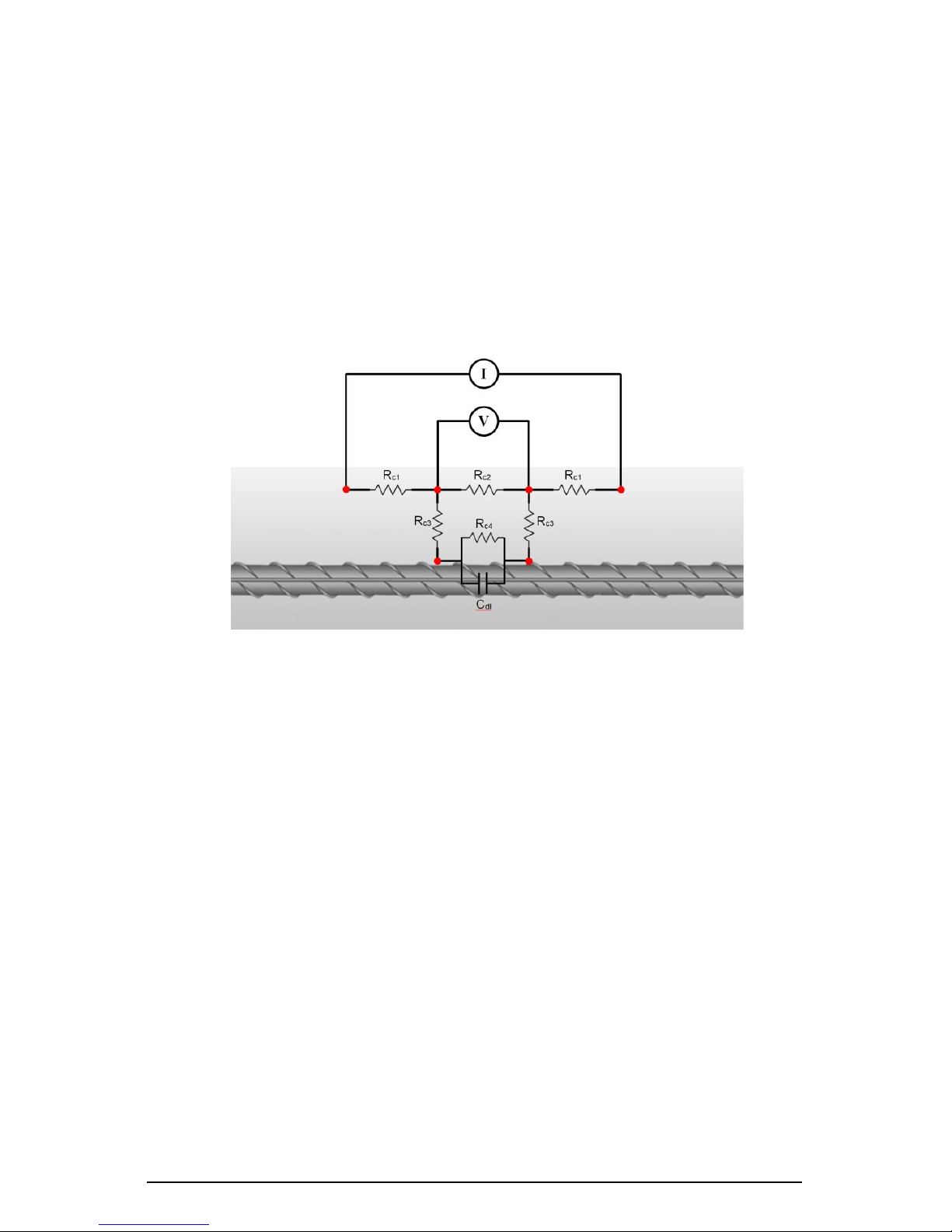
Figure 5. Electrical circuit of reinforced concrete system in
connectionless four-electrode measurement
Giatec iCOR® employs a complex electrical circuit model for predicting
different properties of concrete materials and steel reinforcement. This
electrical circuit is schematically represented in Fig 5. An advanced
mathematical algorithm is implemented in the core software of the device.
This core software processor is responsible for the analysis of certain
characteristics of concrete materials such as the polarization resistance,
electrical resistivity, and half-cell potential of embedded reinforcement.
POLARIZATION RESISTANCE OF REBAR (
R
P
)
This parameter is related to the corrosion rate of rebar in concrete. One can
calculate the corrosion rate from Rp using the following well-stablished
equation:

iCOR® User Manual
© Giatec Scientific Inc. 8
where Ap is the polarized area of rebar, R
c4
is the charge transfer resistance of
rebar defined in Fig. 5 and B is a constant parameter determined
experimentally.
ELECTRICAL RESISTIVITY OF CONCRETE
The intrinsic electrical resistivity of concrete can be calculated from ,
and defined in Fig. 5 using the following equation:
where a is a constant parameter determined from the geometry of the
measurement electrodes, R is the equivalent resistance of concrete calculated
from ,
and .
It is noted that the effect of rebar, unlike other concrete surface resistivity
measurement techniques, would be minimized using this approach. Other
AC techniques have inherent error in the measurement of concrete resistivity
due to the rebar effect.
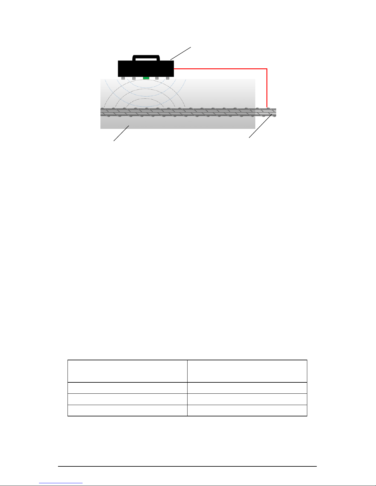
HALF-CELL POTENTIAL MEASUREMENT
iCOR® is also equipped with a reference electrode for half-cell corrosion
measurement (Fig. 6). The purpose of the half-cell potential measurement
is to determine the electrical potential on the surface of concrete which is an
indication of corrosion potential of rebar in concrete.
The potential measurement is used to determine the state of rebar corrosion
in concrete. This technique allows for plotting of a potential contour map on
the concrete surface, which can be used to identify the corroding areas and
estimate the probability of corrosion (Elsener and Bohni, 1995, ASTM C876,
2009).
iCOR® User Manual
© Giatec Scientific Inc. 9
Figure 6. Half-cell potential measurement
APPLICATION
Giatec iCOR® can be used in either field or laboratory applications to
measure the corrosion rate and corrosion potential of steel reinforcement in
concrete structures. This technique can be utilized for various applications
such as:
• Estimation of the corrosion rate of steel reinforcement in concrete
• Measurement of corrosion potential of uncoated reinforcing steel
• Determination of corrosion activity of steel rebar
The measured corrosion potential values are indicative of corrosion
probability as presented in Table 1.
Table 1- Relationship between the potential values and corrosion probability
(adapted from ASTM C876)
Measured Potential (mV/CSE*)
Probability of
Steel Corrosion Activity
> -200
Less than 10%
-200 to -350
Uncertain
< -350
More than 90%
*
CSE= Copper Sulfate Electrode
Rebar
Concrete
Giatec iCOR®
iCOR® User Manual
© Giatec Scientific Inc. 10
It is noted that half-cell potential measurements can also be affected by
testing conditions. RILEM TC-154 (2003) reported the typical ranges for
half-cell potential measurements in different conditions (see Table 2).
Table 2- Typical ranges of half-cell potentials of rebar in concrete (adapted
from RILEM TC-154, 2003)
Condition
Potential values (mV/CSE*)
Humid, chloride free concrete
-200
to
+100
Wet, chloride contaminated concrete
-600
to
-400
Water saturated concrete without oxygen
-1000
to
-900
Humid, carbonated concrete
-400
to
+100
Dry, carbonated concrete
0
to
+200
Dry concrete
0
to
+200
*
CSE= Copper Sulfate Electrode
COMPLICATIONS/ LIMITATIONS
Half-cell potential measurement is a very useful technique in studying the
corrosion of existing structures (or elements). However, this test does not
provide any information on the kinetics of corrosion (i.e., corrosion rate of
steel reinforcement). It is always recommended to interpret corrosion
potential measurements with supplementary data from corrosion rate
measurements as well as other tests (concrete electrical resistivity, cover
thickness, and chloride profile). The presence of large cracks and
delamination can affect both corrosion rate and potential data. In the case of
pre-stressed post-tensioned steel tendons, these tests will not provide any
useful information if the tendons are placed in protective tubes. These tests
are also not applicable to concrete structures with epoxy-coated or galvanized
steel rebar.
While corrosion rate and corrosion potential measurements are quite simple,
the application of these techniques has several complications. For example,
ambient and measurement conditions can influence these measurements.
These complications can lead to misinterpretations of the collected data. The
most important parameters that can influence measurements are briefly
described below:

iCOR® User Manual
© Giatec Scientific Inc. 11
Temperature: The variation in ambient temperature would affect the
corrosion rate, corrosion potential and concrete resistivity measurements. In
a half-cell potential measurement the measured values should be corrected
for the temperature effects (CEFRACOR, 2007); but temperature correction
is not required for the corrosion rate measurement. It is recommended not
to perform the test below freezing point.
Moisture: Concrete moisture has a significant effect on the corrosion rate
and corrosion potential as well as the electrical resistivity of concrete. Since
the moisture of concrete changes from time to time, it can affect the
consistency of measurements (RILEM TC-154, 2003). The drier the concrete
is, the more positive the corrosion potential, the lower the corrosion rate and
the higher electrical resistivity values will be resulted performing the test.
Cover Thickness: The thickness of concrete cover would affect the
corrosion potential as well as the electrical resistivity of concrete. A lower
concrete cover leads to more negative values in half-cell potential
measurements and lower values in concrete electrical resistivity of concrete.
There is limited research on the effect of cover thickness on potential
measurements; hence there is no straightforward correction procedure
(SHRP, 2013). Therefore, it is recommended to verify the cover thickness for
the area being tested in order to avoid misinterpretation of the collected data.
Concrete Properties: Concrete properties such as density, permeability,
porosity, and electrical resistivity are factors that can affect the half-cell
potential measurements. A dense concrete cover reduces the permeability of
chloride and oxygen. This will reduce the oxygen concentration. As a result,
the half-cell potential values tend to be more negative (Gu and Beaudoin,
1998).
Availability of Oxygen: The availability of oxygen at the surface of steel
rebar can affect the corrosion rate and half-cell potential readings. Generally,
a lower concentration of oxygen at rebar level leads to lower corrosion rate
but more negative half-cell potential values (Gu and Beaudoin 1998, Elsener
et al. 2003), which can be misleading.
iCOR® User Manual
© Giatec Scientific Inc. 12
iC O R
®
OV E RV I E W
Giatec iCOR® has two main components: iCOR® Measurement device, and
Data Recording Unit (tablet).
This section describes how to setup and operate the iCOR® device for
measuring the corrosion rate and corrosion potential of steel reinforcement
in concrete structures. Before starting a test, please make sure that the iCOR®
device and your data recording unit are fully charged.
iCOR
®
MEASUREMENT UNIT OVERVIEW
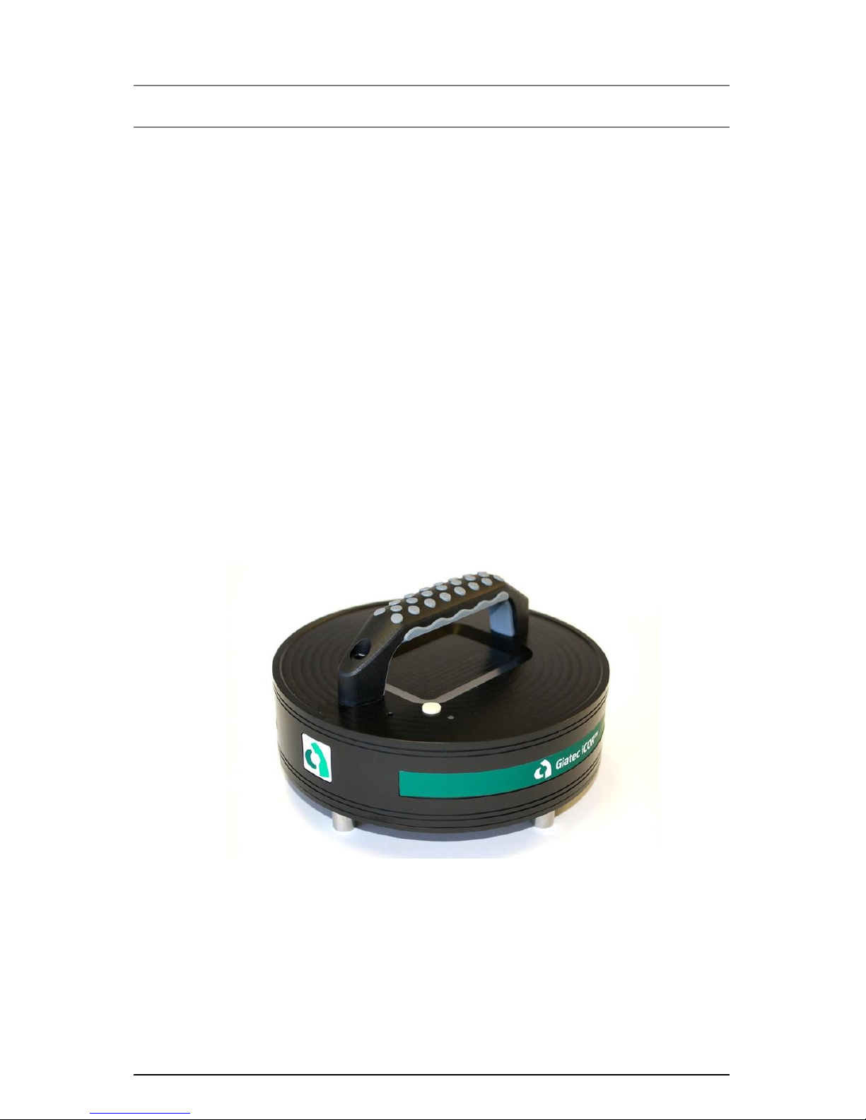
Giatec iCOR® device provides an advanced multi-test platform to measure
the corrosion rate of steel reinforcement, rebar corrosion potential (Halfcell), concrete electrical resistivity, temperature and relative humidity (RH).
The device is equipped with wireless technology to transmit the test data to
the Data Recording Unit (Tablet) (Fig. 7).
Figure 7. Giatec iCOR
®
Measurement Unit
iCOR® User Manual
© Giatec Scientific Inc. 13
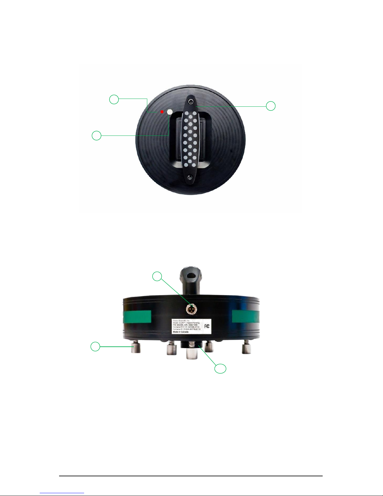
Figures 8 to 10 show the components of the Giatec iCOR® measurement
device.
Figure 8. Giatec iCOR
®
- Top view
1. Notification LED
2. ON/OFF button
3. Handle
Figure 9. Giatec iCOR
®
- Side view
1. Charging/Half-Cell connection terminal
2. Corrosion measurement electrodes
3. Half-cell potential measurement electrode
1
1
2
3
2
3
iCOR® User Manual
© Giatec Scientific Inc. 14
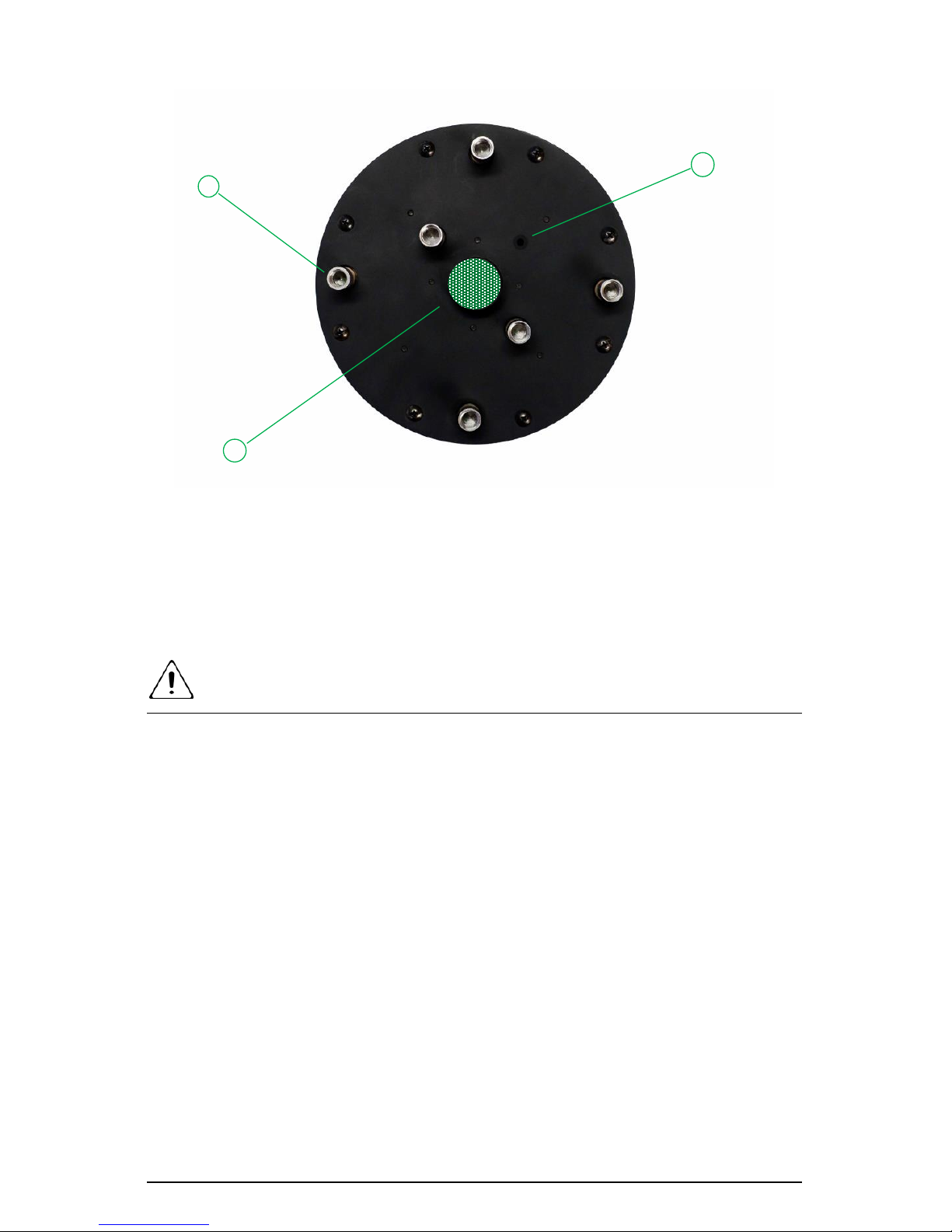
Figure 10. Giatec iCOR – Bottom view
1. Corrosion measurement electrodes
2. Half-cell potential measurement electrode
3. RH/ Temperature sensor inlet
NOTES
• There is a fixed electrochemical potential difference between the
Ag/AgCl electrode (that is used in iCOR®) and the Cu/CuSO4
electrode. The iCOR® software accounts for this difference and
presents the results in mV/CSE (i.e., Cu/CuSO4 Electrode, CSE) as
per ASTM C876.
• The reference electrode used in the measuring device has a
temperature coefficient of -0.65 mV per °C for the temperature
range between 0 to 50 °C. If the temperature compensation mode is
selected in the Giatec iCOR® software, the results are modified and
presented for 25°C.
The Giatec iCOR® half-cell potential measurement unit is equipped
with a maintenance-free electrode. It is not required to refill or
refresh the electrolyte of the electrode.
1
2
3
 Loading...