

Giant-Vac Z-VAC Operator's Manual

ASSEMBLY INSTRUCTIONS
OPERATOR'S MANUAL
PARTS LIST
Z
-VVAC
Mower
Collection
System
Boobcat/Buntoon
Seriess
Actual product may differ slightly from product pictured above
Models covered:
Bagger
Blower
Weight Bar
2-B
3-B
3-BD
48-V
52-V
61-V
48-WB
52-WB
61-WB

1
preliminaries
Congratulations!
You have just purchased one of the finest pieces of outdoor power equipment on the market today. If properly cared for,
your new Z-Vac Mower Collection System will provide years of dependable service. Please read and follow this instruction manual carefully in order to get the most out of your new equipment.
As you carefully unpack your unit, you will find the following items:
1 Z-Vac Blower Unit
1 Bagger Unit with Mounting Kit
1 Weight Bar Kit
1 Package containing operating manuals and warranty registration
Each product leaves our factory in excellent condition; occasionally, however, some damage may occur during shipment.
If any such damage is found upon initial inspection, immediately notify the transport carrier who delivered your machine,
as they are solely responsible for such damage, as well as any subsequent adjustments necessary.
Before assembly, please take a moment and record your model number and serial number below for future reference (both
numbers are located on the silver tag adhered to the rear of the unit, below and to the right of the engine):
Model number_______________________________
Serial number________________________________
Also be sure to promptly fill out and return the warranty registration enclosed in your manual packet.
Your new Z-Vac requires very little assembly. Simply follow the instructions contained within this manual to begin enjoying the benefits of your new unit.
2
GVTP ZVBB-R0203.1

safety rules regarding outdoor power equipment
2
TRAINING
-- Read, understand, and follow all instructions in the man-
ual and on the unit before starting. If the operator(s) or
mechanic(s) can not read English it is the owner's responsibility to explain this material to them.
-- Become familiar with the safe operation of the equipment,
operator controls, and safety signs.
-- All operators and mechanics should be trained. The
owner is responsible for training the users.
-- Only allow responsible adults, who are familiar with the
instructions, to operate the unit.
-- Never let children or untrained people operate or service
the equipment. Local regulations may restrict the age of the
operator.
-- The owner/user can prevent and is responsible for accidents or injuries occurring to themselves, other people or
property.
PREPARATION
-- Evaluate the terrain to determine what accessories and
attachments are needed to properly and safely perform the
job. Use only accessories and attachments approved by
the manufacturer.
-- Wear appropriate clothing including safety shoes, safety
glasses and ear protection. Long hair, loose clothing or jewelry may get tangled in moving parts.
-- Inspect the area where the equipment is to be used and
remove all objects such as rocks, toys and wire, which can
be thrown by the machine.
-- Use extra care when handling gasoline and other fuels.
They are flammable and vapors are explosive.
a) Use only an approved container.
b) Never remove fuel cap or add fuel with the engine running. Allow engine to cool before refueling. Do not smoke.
c) Never refuel or drain the machine indoors.
-- Check that operator's presence controls, safety switches
and shields are attached and functioning properly. Do not
operate unless they are functioning properly.
OPERATION
-- Never run an engine in an enclosed area.
-- Operate only in the daylight or with good artificial light,
keeping away from holes and hidden hazards.
-- Be sure of your footing while using pedestrian controlled
equipment, especially when backing up. Walk, don't run.
-- Do not operate in reverse unless absolutely necessary.
Always look down and behind before and while traveling in
reverse.
-- Be aware of the blower discharge direction and do not
point it at anyone. Do not operate the blower without hose
and bagger hood in place.
-- Never leave a running unit unattended. Always stop
engine before leaving unit.
-- Never operate with guards not securely in place. Be sure
all safety features are attached, adjusted properly and functioning properly.
-- Never operate with the hose or hood removed or altered.
-- Do not change the engine governor setting or over speed
the engine.
-- Stop on level ground, shut off engine before leaving the
operator's position for any reason.
-- Stop equipment and inspect impeller blades after striking
objects or abnormal vibration occurs. Make necessary
repairs before resuming operations.
-- Keep hands and feet away intake and discharge areas.
-- Keep pets and bystanders away.
-- Do not operate the unit while under the influence of alco-
hol or drugs.
-- Use caution when crossing roads and sidewalks. Stop
engine if not blowing.
-- Use care when loading or unloading the machine into a
trailer or truck.
-- Use care when approaching blind corners, shrubs, trees
or other objects that may obscure vision.
SLOPE OPERATION
Slopes are a major factor related to loss-of-control and tipover accidents, which can result in severe injury or death.
All slopes require extra caution. If you cannot back up the
slope, or if you feel uneasy on it, do not drive on it.
Do
-- Mow across the face of slopes; never up and down.
-- Remove obstacles such as rocks, tree limbs, etc.
-- Watch for holes, ruts, or bumps. Uneven terrain could
overturn the unit. Tall grass can hide obstacles.
-- Keep all movement on the slopes slow and gradual. Do
not make sudden changes in speed or direction.
Do Not
-- Do not start or stop on a slope. If tires lose traction, pro-
ceed slowly straight down the slope.
-- Do not turn on slopes unless necessary, and then, turn
slowly and gradually downhill, if possible.
-- Do not use near drop-offs, ditches, or embankments. The
operator could lose footing or balance or blower could suddenly turn over if a wheel is over the edge of a cliff or ditch,
or if an edge caves in.
-- Do not operate on slopes with wet grass. Reduced footing or traction could cause sliding.
-- Do not use on excessively steep slopes.
IMPORTANT! READ CAREFULLY THE FOLLOWING SAFETY RULES BEFORE
ASSEMBLING OR OPERATING UNIT.
3
GVTP ZVBB-R0203.1

2
safety rules regarding outdoor power equipment
CHILDREN
Tragic accidents can occur if the operator is not alert to the
presence of children. Children are often attracted to the unit
and its activity. Never assume that children will remain
where you last saw them.
-- Keep children out of the mowing area and under the
watchful care of another responsible adult.
-- Be alert and turn unit off if children enter the area.
-- Before and during reverse operation, look behind and
down for small children.
-- Never allow children to operate the unit.
-- Use extra care when approaching blind corners, shrubs,
trees, or other objects that may obscure vision.
EMISSIONS
-- Engine exhaust from this product contains chemicals
known, in certain quantities, to cause cancer, birth defects,
or other reproductive harm.
-- Look for the relevant Emissions Durability Period and Air
Index information on the engine emissions label.
MAINTENANCE AND STORAGE
-- Always observe safe refueling and fuel handling practices
when refueling the unit after transportation or storage.
-- Always follow the engine manual instructions for storage
preparations before storing the unit for both short and long
term periods.
-- Always follow the engine manual instructions for proper
start-up procedures when returning the unit to service.
-- Never store the machine or fuel container inside where
there is an open flame, such as in a water heater. Allow unit
to cool before storing.
-- Shut off fuel while storing or transporting. Do not store fuel
near flames or drain indoors.
-- Keep all hardware tight and keep all parts in good working condition. Replace all worn or damaged decals.
-- Never tamper with safety devices. Check their proper
operation regularly.
-- Clean leaves and debris from mufflers and engine to prevent fires. Clean up oil or fuel spillage.
-- Stop and inspect the equipment if you strike an object.
Repair, if necessary, before restarting.
-- Never make adjustments or repairs with the engine running unless specified otherwise.
-- Park machine on level ground. Never allow untrained personnel to service machine.
-- Carefully release pressure from components with stored
energy. (e.g. springs)
-- Only replace impellers. Never straighten or weld them.
-- Keep hands and feet away from moving parts.
-- Frequently check components and replace with manufac-
turer's recommended parts, when necessary.
-- Use only factory authorized replacement parts when making repairs.
-- Always comply with factory specifications on all settings
and adjustments.
-- Only authorized service locations should be utilized for
major service and repair requirements.
-- Never attempt to make major repairs on this unit unless
you have been properly trained. Improper service procedures can result in hazardous operation, equipment damage and voiding of manufacturer's warranty.
4
GVTP ZVBB-R0203.1

unit assembly
3
Deflector Removal - All Models
Remove hardware securing Discharge
Deflector to mower deck and remove deflector.
Important Note: Reattach hardware to deflector and store for future use. Never operate any
mower without a discharge deflector securely
in place.
Deck Pulley Guard Removal All Models
Remove hardware securing right deck pulley
guard to mower deck and remove guard. Set
hardware aside for future vac assembly step.
Important Note: Store guard for future use.
Never operate any mower without a pulley
guard securely in place.
Vac Pulley Installation - All Models
Lifting up foot rest/center deck cover to expose
center blade deck, insert a 3/8” drive breaker
bar with an extension into the tension release
hole in the blade belt idler arm and twist counterclockwise to relieve tension, while slipping
blade belt from right blade drive pulley.
Note: Assistance may be needed for removal
of blade belt.
Remove right blade pulley, replacing with supplied two-tiered Z-Vac drive pulley. Use same
hardware as hardware removed, making sure
to tighten securely to manufacturer’s specs.
Replace blade belt around bottom tier of pulley, using method described above. Close foot
rest/center deck cover.
Note: Assistance may be needed for replacement of blade belt.
5
GVTP ZVBB-R0203.1

3
unit assembly
6
Vac Belt Installation - All Models
Install Z-vac drive belt onto top tier of vac drive
pulley. Be sure belt runs through vac idler system correctly; also be sure there is no belt
rollover.
Note: Pull back tension release lever on idler
arm (see inset) to give extra belt slack when
installing.
Belt Guard Installation - All Models
(61” shown)
Install Vac Drive belt guard using existing rider
hardware. Tighten securely.
Install vac unit pulley guard (inset) with three
5/16-18 x 3/4” ‘F’ thread bolts. Tighten securely.
Vac Unit Installation - All Models
(61” shown)
Fit Z-Vac unit into place over and against
mower discharge, aligning holes in discharge
mounting brackets with holes in Z-vac mounting bracket. Insert one 3/8 x 2” clevis pin into
each of the two mounting holes, securing with
bridge pins.
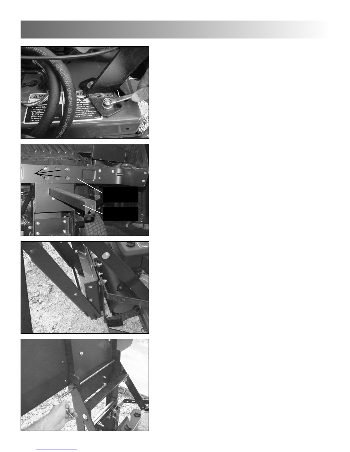
Lock unit firmly in place with T-bolt as shown.
GVTP ZVBB-R0203.1

Weight Bar Kit Installation - All Models
(61” shown)
!! Warning: Weight kit must be installed
prior to installing bagger unit. Failure to do
so may result in longitudal tipping of unit.
Lay weight mount channel across front end of
unit as shown. Secure to unit with two clamp
plates, one under each caster arm, each held
on with two 3/8-16 x 3-1/4” hex bolts and two
reverse lock nuts. Tighten securely.
Secure weight bars to weight mount channel
with three 1/2-13 x 3-1/4” hex bolts and three
serrated flange nuts. Tighten securely.
!! Warning: Always install all
supplied
weight bars onto weight mount channel.
Failure to do so may result in longitudal tipping of unit.
Bagger Installation - 2 Bag Units
Assemble bumper mount plate onto rear
bumper bar of mower. Use two bar clamps on
top portion of plate, fastening from in front of
bumper bar, with four 3/8-16 x 1-1/4” hex bolts
and serrated flange nuts. Fasten bottom with
one bumper spacer and same hardware as
above. Tighten all hardware securely.
Assemble the upper reinforcement brace as
shown, using two 3/8-16 x 1-1/4” hex bolts, fitted with two 3/8” flat washers, and securing
with two 3/8-16 serrated flange nuts. Do not
tighten hardware.
unit assembly
3
7
Top View
Rear View
GVTP ZVBB-R0203.1
Set bottom of support assembly onto pins in
bottom of bumper mount.
Holding support assembly upright, align holes
in support assembly with corresponding holes
in bumper mount and reinforcement brace.
Slide 5/8 x 17” locking pin through holes in
bumper mount, securing with 2-1/2” oal bridge
pin. Slide 3/8 x 18” locking pin through holes
in top of reinforcement brace, securing with 17/8” oal bridge pin.
Now tighten all brace hardware securely.
3
unit assembly
Bagger Installation - 2 Bag Units
(Cont.)
Install the reinforcement brace assembly onto
the unit, utilizing the square holes in the
engine base. Secure with four 5/16-18 x 3/4”
carriage bolts (inserted up from under the
engine base) and serrated flange nuts. Note:
Do not tighten brace hardware until support
assembly in following steps is installed.
Attach Cross Assembly (with attached hood
assembly) to Cover Support Assembly with
four 3/8-16 x 3/4 hex bolts and four 3/8-16 serrated flange nuts. Tighten securely.
Attach Cover Latch Arm to Cover Support
Assembly with two 5/16-18 x 3/4 hex bolts and
5/16-18 serrated flange nuts. Tighten securely.
8
Bolts
Cross
Assembly
Cover Latch
Arm
GVTP ZVBB-R0203.1
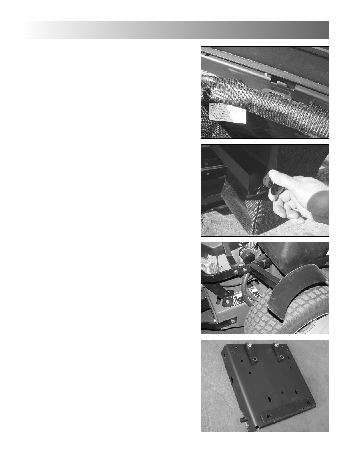
Bagger Installation - 2 Bag Units
(Cont.)
Lift cover and install bags onto plate/channel
assembly by hooking slot in bag hanger onto
tabs in channel assembly.
Close cover and lock in place by hooking lock
knob into slot in cover latch arm.
Using the mounting bracket at the foot of the
Discharge Hose Standoff as a template, drill
two 7/16” holes into the right upper rear
bumper bar of the rider, just forward of the rear
radiator support bar bolt head. Fasten standoff to bumper bar with two 5/16-18 x 1 hex
bolts and serrated flange nuts. Tighten
securely. Note: Make sure standoff angles
upwards upon installation.
Proceed to Discharge Hose Installation.
Bagger Installation - 3 Bag Units
Preassemble bumper mount plate as shown,
securing two sets of two short clamp bars into
top of plate with one 3/8-16 x 1-3/4” hex bolt
and serrated flange nut. Leave nuts loose.
Also note position of bottom clamp bar that will
be addressed in following step.
unit assembly
3
9
GVTP ZVBB-R0203.1
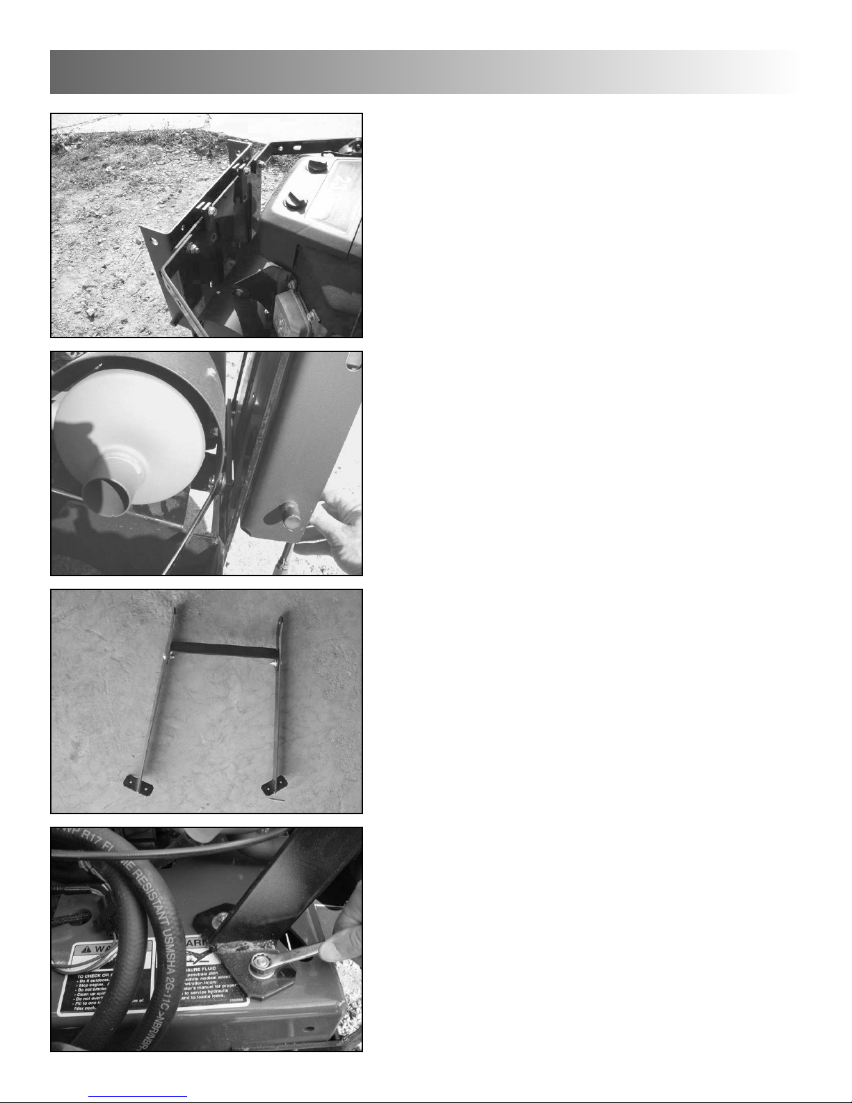
Assemble the upper reinforcement brace as
shown, using two 3/8-16 x 1-1/4” hex bolts,
each fitted with one 3/8” flat washer, and
secure with two 3/8-16 serrated flange nuts.
Do not tighten hardware.
Install the reinforcement brace assembly onto
the unit, utilizing the square holes in the
engine base. Secure with four 5/16-18 x 3/4
carriage bolts (inserted up from under the
engine base) and serrated flange nuts. Note:
Do not tighten brace hardware until support
assembly in following steps is installed.
3
unit assembly
Bagger Unit Installation - 3 Bag Units
(Cont.)
Hook bumper mount plate onto rear bumper,
making sure one bar clamp is in front of
bumper, another behind. Secure in place with
same hardware in lower set of holes as in previous step. Do not tighten yet.
Repeat the same for the bottom part of the
mount, using the long clamp bar, one on the
inside and one on the outside of the bumper.
Insert two 3/8-16 x 1-3/4” bolts from the
bumper mount side, securing with two 3/8 flat
washers and two 3/8-16 nylon lock nuts.
Tighten securely.
10
GVTP ZVBB-R0203.1
 Loading...