


ASSEMBLY INSTRUCTIONS
OPERATOR’S MANUAL
PARTS LIST
‘Giant-Mow’
Walk-Behind
Mower
32”
Actual product may differ slightly from product pictured above
cut models
Models covered:
M32125KAW
M3213BS
M3213BS-E

This page intentionally blank
GVTP GM32-R0103.1

1
preliminaries
Congratulations!
You have just purchased one of the finest pieces of outdoor power equipment on the market today. If properly
cared for, your new mower will provide years of dependable service. Please read and follow this instruction
manual carefully in order to get the most out of your new equipment.
As you carefully uncrate your unit, you will find the following items:
1 Mower Unit
1 Caster Kit including:
2 - Caster arms
2 - Caster horns with mounted wheels and spacers
1 Fuel Tank Kit including:
1 – Fuel tank
2 – Fuel tank straps
1 – Fuel tank cap
1 Handle Bar Kit including:
1 – Handle assembly with mounted brake and safety levers
1 – Deflector chute
1 – Transmission shift lever assembly
2 – Upper brake rods
1 – Blade engagement lever assembly (125KAW & 13BS only)
2 – Fuel tank mounting brackets (left & right w/rubber strips)
1 – Battery (with overflow tube and terminal hardware – 13BS-E only)
1 – Package of assembly hardware
1 – Package containing operating manuals and warranty registration
Each product leaves our factory in excellent condition; occasionally, however, some damage may occur during
shipment. If any such damage is found upon initial inspection, immediately notify the transport carrier who
delivered your machine, as they are solely responsible for such damage, as well as any subsequent
adjustments necessary.
Before assembly, please take a moment and record your model number and serial number below for
future reference (both numbers are located on the silver tag adhered to the rear of the engine deck):
Model number_______________________________
Serial number________________________________
Also be sure to promptly fill out and return the warranty registration enclosed in your manual packet.
Your new mower requires very little assembly. Simply follow the instructions contained within this manual to
begin enjoying the benefits of your new unit.
Gasoline and Diesel engine exhaust and some of its constituents are known to the State of California to cause cancer, birth defects and
other reproductive harm.
As an owner of off-road gasoline or diesel engine equipment and/or as an employer, you also may have an obligation under the
California Occupational Safety and Health Act or under Proposition 65 to warn persons exposed to gas and diesel engine exhaust
and/or other Proposition 65 chemicals in and around your workplace. See California Health and Safety Code section 25249.5, Title 22 of
the California Code of Regulations at Section 1200 er seq., and Title 8 of the California Code of Regulations Section 5194.
CALIFORNIA PROPOSITION 65 WARNING
R0103.1
GVTP GM32-R0103.1

2
safety rules regarding outdoor power equipment
PLEASE READ THE FOLLOWING BEFORE ASSEMBLING OR OPERATING UNIT
TRAINING
• Read, understand, and follow all instructions in the
manual and on the unit before starting. If the
operator(s) or mechanic(s) can not read English it is
the owner’s responsibility to explain this material to
them.
• Become familiar with the safe operation of the
equipment, operator controls, and safety signs.
• All operators and mechanics should be trained.
The owner is responsible for training the users.
• Only allow responsible adults, who are familiar
with the instructions, to operate the unit.
• Never let children or untrained people operate or
service the equipment. Local regulations may
restrict the age of the operator.
• The owner/user can prevent and is responsible for
accidents or injuries occurring to themselves, other
people or property.
PREPARATION
• Evaluate the terrain to determine what
accessories and attachments are needed to
properly and safely perform the job. Use only
accessories and attachments approved by the
manufacturer.
• Wear appropriate clothing including safety shoes,
safety glasses and ear protection. Long hair, loose
clothing or jewelry may get tangled in moving parts.
• Inspect the area where the equipment is to be
used and remove all objects such as rocks, toys
and wire, which can be thrown by the machine.
• Use extra care when handling gasoline and other
fuels. They are flammable and vapors are
explosive.
a) Use only an approved container.
b) Never remove fuel cap or add fuel with the
engine running. Allow engine to cool before
refueling. Do not smoke.
c) Never refuel or drain the machine indoors.
• Check that operator’s presence controls, safety
switches and shields are attached and functioning
properly. Do not operate unless they are functioning
properly.
OPERATION
• Never run an engine in an enclosed area.
• Mow only in the daylight or with good artificial
light, keeping away from holes and hidden hazards.
• Be sure transmission is in neutral and cutting
blades are disengaged before starting engine.
• Be sure of your footing while using pedestrian
controlled equipment, especially when backing up.
Walk, don’t run.
• Do not mow in reverse unless absolutely
necessary. Always look down and behind before
and while traveling in reverse.
• Be aware of the mower discharge direction and do
not point it at anyone. Do not operate the mower
without either the entire grass catcher or the
deflector in place.
• Slow down and use caution when making turns
and when changing directions on slopes.
• Never raise deck with the blades running.
• Never leave a running unit unattended. Always
disengage cutting blades, set transmission in
neutral, stop engine, and remove keys before
leaving unit. Keep hands and feet away from the
cutting units.
• Disengage the cutting blades when not mowing.
• Never operate with guards not securely in place.
Be sure all safety features are attached, adjusted
properly and functioning properly.
• Never operate with the discharge deflector raised,
removed or altered, unless using a grass catcher.
• Do not change the engine governor setting or over
speed the engine.
• Stop on level ground, disengage cutting blades,
set transmission in neutral, shut off engine before
leaving the operator’s position for any reason
including emptying the grass catchers or
unclogging the chute.
• Stop equipment and inspect blades after striking
objects or abnormal vibration occurs. Make
necessary repairs before resuming operations.
• Keep hands and feet away from the cutting units.
• Never carry passengers and keep pets and
bystanders away.
• Do not operate the unit while under the influence
of alcohol or drugs.
• Slow down and use caution when making turns
and crossing roads and sidewalks. Stop blades if
not mowing.
• Use care when loading or unloading the machine
into a trailer or truck.
• Use care when approaching blind corners, shrubs,
trees or other objects that may obscure vision.
GVTP GM32-R0103.1

2
safety rules regarding outdoor power equipment (cont.)
SLOPE OPERATION
Slopes are a major factor related to loss-of-control
and tip-over accidents, which can result in severe
injury or death. All slopes require extra caution. If
you cannot back up the slope, or if you feel uneasy
on it, do not drive on it.
Do
• Mow across the face of slopes; never up and
down.
• Remove obstacles such as rocks, tree limbs, etc.
• Watch for holes, ruts, or bumps. Uneven terrain
could overturn the unit. Tall grass can hide
obstacles.
• Use slow speed. Choose a slow speed so that you
will not have to stop or change speed while on the
slope.
• Use extra care with grass catchers or other
attachments. These can change the stability of the
unit.
• Keep all movement on the slopes slow and
gradual. Do not make sudden changes in speed or
direction.
Do Not
• Do not start or stop on a slope. If tires lose
traction, disengage the blade and proceed slowly
straight down the slope.
• Do not turn on slopes unless necessary, and then,
turn slowly and gradually downhill, if possible.
• Do not mow near drop-offs, ditches, or
embankments. The operator could lose footing or
balance or mower could suddenly turn over if a
wheel is over the edge of a cliff or ditch, or if an
edge caves in.
• Do not mow on wet grass. Reduced footing or
traction could cause sliding.
• Do not mow excessively steep slopes.
• Do not use grass catcher on steep slopes.
CHILDREN
Tragic accidents can occur if the operator is not
alert to the presence of children. Children are often
attracted to the unit and the mowing activity. Never
assume that children will remain where you last
saw them.
• Keep children out of the mowing area and under
the watchful care of another responsible adult.
• Be alert and turn unit off if children enter the area.
• Before and during reverse operation, look behind
and down for small children.
• Never carry children. They may fall off and be
seriously injured or interfere with safe unit
operation.
• Never allow children to operate the unit.
• Use extra care when approaching blind corners,
shrubs, trees, or other objects that may obscure
vision.
EMISSIONS
• Engine exhaust from this product contains
chemicals known, in certain quantities, to cause
cancer, birth defects, or other reproductive harm.
• Look for the relevant Emissions Durability Period
and Air Index information on the engine emissions
label.
MAINTENANCE AND STORAGE
• Always observe safe refueling and fuel handling
practices when refueling the unit after
transportation or storage.
• Always follow the engine manual instructions for
storage preparations before storing the unit for both
short and long term periods.
• Always follow the engine manual instructions for
proper start-up procedures when returning the unit
to service.
• Never store the machine or fuel container inside
where there is an open flame, such as in a water
heater. Allow unit to cool before storing.
• Shut off fuel while storing or transporting. Do not
store fuel near flames or drain indoors.
• Keep all hardware, especially blade attachment
bolts, tight and keep all parts in good working
condition. Replace all worn or damaged decals.
• Never tamper with safety devices. Check their
proper operation regularly.
• Clean grass and debris from cutting units, drives,
mufflers, and engine to prevent fires. Clean up oil or
fuel spillage.
• Stop and inspect the equipment if you strike an
object. Repair, if necessary, before restarting.
• Never make adjustments or repairs with the
engine running unless specified otherwise.
• Park machine on level ground. Never allow
untrained personnel to service machine.
• Use jack stands to support components when
required.
• Carefully release pressure from components with
stored energy. (e.g. springs)
• Use care when checking blades. Wrap the
blade(s) or wear gloves, and use caution when
servicing them. Only replace blades. Never
straighten or weld them.
• Keep hands and feet away from moving parts.
GVTP GM32-R0103.1

2
safety rules regarding outdoor power equipment (cont.)
• Grass catcher components are subject to wear,
damage, and deterioration, which could expose
moving parts or allow objects to be thrown.
Frequently check components and replace with
manufacturer’s recommended parts, when
necessary.
• Check brake operation frequently. Adjust and
service as required.
• Use only factory authorized replacement parts
when making repairs.
• Always comply with factory specifications on all
settings and adjustments.
• Only authorized service locations should be
utilized for major service and repair requirements.
• Never attempt to make major repairs on this unit
unless you have been properly trained. Improper
3
Note: Please refer to Parts List for correct part identification and placement. Parts list reference
numbers are called out by sheet number followed by reference number(s) on that sheet: (1:1) indicates
Sheet 1, reference number 1; (2:32,34-38) indicates Sheet 2, reference numbers 32 through 38 excluding
33; etc.
unit assembly
service procedures can result in hazardous
operation, equipment damage and voiding of
manufacturer’s warranty.
CASTER ASSEMBLY
• Remove Lynch pin (1:19) and all but the bottom
1/4” spacer (1:18) from Caster horn (1:15).
• Slide Caster horn up through Caster arm (1:9),
securing with same spacers and lynch pin
removed in previous step. NOTE: When
assembled in this manner, cutting height will be
approximately 2-1/2".
• With front of mower propped up, install caster
assemblies to front of Blade Deck (1:1) with
twelve 3/8" x 1" bolts, flat washers, lock
washers and nuts (1:10-13). (Bolts are
installed from inside of mower deck.) Tighten
all bolts securely. Lower front of mower.
GVTP GM32-R0103.1
3
unit assembly (cont.)
DISCHARGE DEFLECTOR ASSEMBLY
• Attach discharge deflector (1:6) using two 5/16"
x ¾" bolts and lock nuts (1:7-8). CAUTION:
Do not over tighten lock nuts.
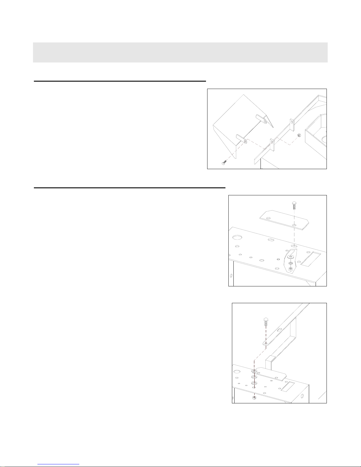
TRANSMISSION SHIFT LEVER ASSEMBLY
• Install Shift indicator panel (2:50) onto rear of
engine deck (2:1) with two 5/16 x 3/4” hex bolts
(2:52), securing with flat washers, lock washers
and nuts (2:53-55). Leave hardware finger
tight.
• Remove 3/8” nylon lock nut and flat washer
(2:47,49) from shift stud atop transmission
(2:17 – location ‘A’).
• Remove 1/2 x 2-1/2” hex bolt, three oillite
washers, and lock nut (2:44-46) from top rear of
engine deck.
• Insert same 1/2” bolt down through top forward
hole in Shift lever (2:42), slip same three
washers up onto threads of bolt, then drop bolt
into same hole.
GVTP GM32-R0103.1
3
unit assembly (cont.)
TRANSMISSION SHIFT LEVER ASSEMBLY (cont.)
• Position ‘double-D’ hole in bottom leg of shift
lever onto transmission stud, then slowly move
handle of shifter back and forth until hole drops
onto matching base of stud.
• Replace washer and nut onto transmission
stud. Tighten securely. Replace lock nut onto
1/2” bolt. Tighten snugly while allowing for
shifter movement.
• Work shift lever through gear range, adjusting
indicator panel for display alignment, then
tighten indicator panel hardware.
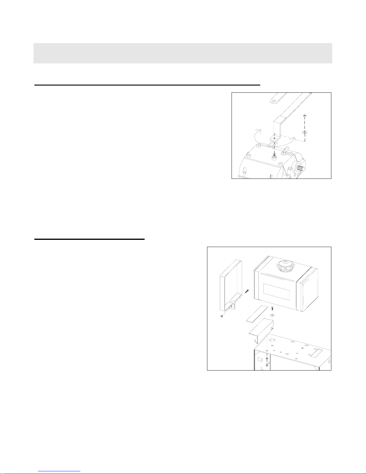
FUEL TANK ASSEMBLY
• Install fuel tank mount brackets (2:56 – right
side shown) onto engine deck using four 5/16 x
¾” hex bolts, flat washers, lock washers and
nuts (2:57-60). Do not tighten.
• Place rubber pads (2:61) on top of mount
brackets.
• Place fuel tank (2:65) on top of rubber pads.
• Slip fuel tank straps (2:62) around ends of tank,
making sure bottom of straps slip under top
ends of mounting brackets and into notches.
Secure each strap with one 1/4 x 1-1/2” hex
bolt and lock nut (2:63-64). Tighten both strap
and mounting bracket hardware securely.
• Slip end of fuel line from engine fully onto
barbed nipple of fuel shut-off valve (located
under tank), securing with supplied spring
clamp.
GVTP GM32-R0103.1
3
unit assembly (cont.)
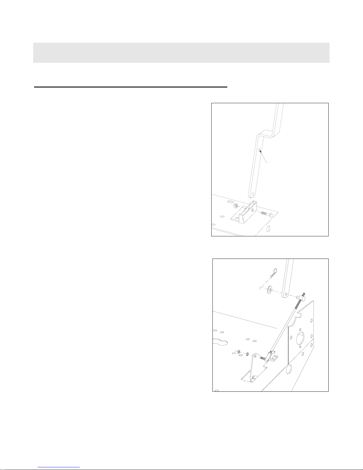
BLADE ENGAGEMENT LEVER ASSEMBLY
(125KAW & 13BS only)
• Remove bridge pin and washer (4b:14-15)
holding adjustment rod to engagement lever
(4b:1) and remove upper adjustment rod
assembly (4b:13,16-20).
• Remove 3/8” bolt and lock nut (4b:4-5) from
engagement lever bracket (4b:3 – attached to
engine deck). Slip bottom of lever down
through slot in engagement lever bracket,
making sure bend is toward left side of mower
to give clearance for fuel tank assembly. Reinstall bolt and lock nut through top hole in
lever. (CAUTION: Do not over tighten lock
nut).
• Remove jam nut and lock washer (4b:19-20)
from ball joint (4b:18); install ball-joint stud
through hole in blade belt cam (4b:21) with nut
and lock washer toward right side of mower.
Adjust rod length to ensure cam locks when
lever is fully engaged and attach to lower end of
handle with washer and bridge pin previously
removed.
bolt goes thru
this hole
GVTP GM32-R0103.1

3
unit assembly (cont.)
HANDLE ASSEMBLY INSTALLATION
• Install handle assembly (5:1) to upper portion of
engine deck using four 1/2" x 1-1/4" hex bolts,
lock washers and nuts (5:3,5-6), with two flat
washers (5:4) at slotted holes. Adjust for
comfortable operation, then tighten securely.
• Locate wiring harness and route harness up the
right side of handle assembly. Standard
Models: Attach one terminal (marked) to
ignition switch (5:28); attach the second
terminal to the handle safety switch (5:21).
Electric Start Models: Follow routing
instructions on Sheet 7 at the back of this
manual. Attach harness to right handle bar with
two plastic tie wraps.
• Locate throttle control (5:24 – attached to
engine) and route cable up left side of handle
assembly. Attach control to under handle dash
using two 8-32 x 1/2" machine screws, lock
washers and nuts. Attach cable to left side of
mower handle using metal cable clip. Install
push on plastic throttle handle knob (5:27).
Adjust throttle cable for proper operation at
carburetor end.
• Install "L" shaped end of upper brake rod
(5:11), from outside, through brake handle (5:7)
and brake lock handle (5:12). Secure with
fender washer and bridge pin (5:16-17). Attach
adjustable rod fitting end (3:44) on lower end of
rod to side idler plate (3:21) using flat washer
and bridge pin (3:45-46). Repeat for other side.
IMPORTANT: Adjust upper rods for handle
comfort and proper drive belt release; also
adjust lower brake rods (3:14), by means of
5/16” wing nut (3:20) so that brakes will hold
firmly when brake lock handle is engaged.
GVTP GM32-R0103.1

3
unit assembly (cont.)
BATTERY INSTALLATION (13BS-E only)
*Important Note: Battery must be filled with acid before installation, as batteries are shipped without
acid for safety purposes. Battery acid can be obtained from any auto parts store. Do not overfill.
• Remove hardware securing battery box cover
(6:3) to battery box, and remove cover.
• Fill battery (6:1) with acid*, then install battery
into battery box, making sure positive terminal
(‘+’) is toward front of mower, negative (‘-‘) is
toward rear.
• Removing bolt from battery positive (‘+‘)
terminal (making sure not to lose nut plate
inside terminal), lay loose end of positive cable
(6:14 - attached to solenoid) on top of terminal
and fasten with same bolt as previously
removed. Tighten securely.
• Removing bolt from battery negative (‘-‘)
terminal (making sure not to lose nut plate
inside terminal), lay loose end of ground cable
(6:6 -attached to left axle bearing top bolt) on
top of terminal and fasten with same bolt as
previously removed. Tighten securely.
• Place rubber battery cover (6:2) over top of
battery.
• Replace battery box cover, securing with same
hardware removed in previous step. Tighten
securely.
• Inspect cables to make sure no contact is made
with moving parts.
Your mower is now ready to be started and checked for proper operation. Some minor
final adjustments may be required; see the Maintenance portion of this manual.
GVTP GM32-R0103.1

4
unit operation
STARTING THE ENGINE
IMPORTANT NOTE: The procedures outlined within this section are general guidelines, and are in no way
meant to replace or supercede engine manufacturer’s operating instructions. In order to obtain optimum
performance from your engine, refer to your engine manual.
BEFORE STARTING ENGINE:
• Be sure that the unit is completely assembled, all fasteners are tightened securely, and all safety guards
and components are in place.
• Be sure to check engine’s oil and gasoline*. (See engine manual for recommended oil and gasoline
specifications.) Never check the engine while it is running or while you are smoking. Check only when
engine is cold.
* All machines are shipped without oil or gasoline unless otherwise noted.
• Be sure that fuel valve on tank is set to open
position.
CLOSED
OPEN
TO START ENGINE:
• Set throttle control to “Start” position. If your
engine has a fuel prime button, depress it firmly
three times.
125KAW & 13BS -
• Turn ignition key to ‘run’ position.
GVTP GM32-R0103.1
 Loading...