

GIANT PUMPS P55W, P56W, P56W-HK, P56W-0011, P56W-0021 Repair Instructions
...
Repair Instructions
P55W/P56W/P56W-HK/P56W-0011/P56W-0021/P56W-0121
NOTE: Always take time to lubricate all metal and nonmetal parts with a light fi lm of oil before reassembly.
This step will ensure proper fi t, at the same time protecting the pump nonmetal parts (i.e., the elastomers)
from cutting and scoring.
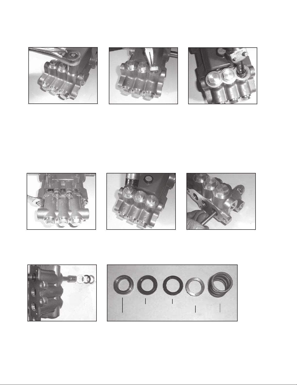
1. With a 22mm socket, remove
the three discharge (43)
and three inlet (41) manifold
plugs. Check o-rings (42 and
44) for wear and replace as
necessary.
4. Drain the oil from the pump.
Turn the pump over to
remove the four manifold
stud nuts (46) with a 17mm
wrench.
2. Remove the discharge
spring retainer (34), valve
spring (35), and valve plate
(36).
5. Tap the back of the manifold
(29) with a rubber mallet to
dislodge, and slide off the
pump.
3. Using a small slide hammer
remove valve seats (37) from
manifold (29). Inspect valve
plates (36) and valve seats
(37) for wear. If excessive
pitting is seen, replace the
worn parts. Check valve seat
o-ring (38) for wear and replace as necessary. Tighten
manifold plugs (43) to 52
ft.-lbs. (70 Nm).
6. From the front inlet valve
ports, remove the inlet valve
assembly (34-40) and pressure springs (33).
7. Turn the manifold (29) over.
Using a 15mm socket, tap
out the v-sleeves (31/31Afor P56W-HK), support rings
(32), and pressure rings (30)
through back of manifold.
31
30 32 33
8. Inspect and clean the manifold (29) and pressure ring
(32). Reinstall the pressure ring (30) with the groved side
pointed towards the front. Insert v-sleeves (31/31A), support ring (32), and pressure spring (33) into the manifold.
31A
(P56W-HK only)
8
Repair Instructions
P55W/P56W/P56W-HK/P56W-0011/P56W-0021/P56W-0121
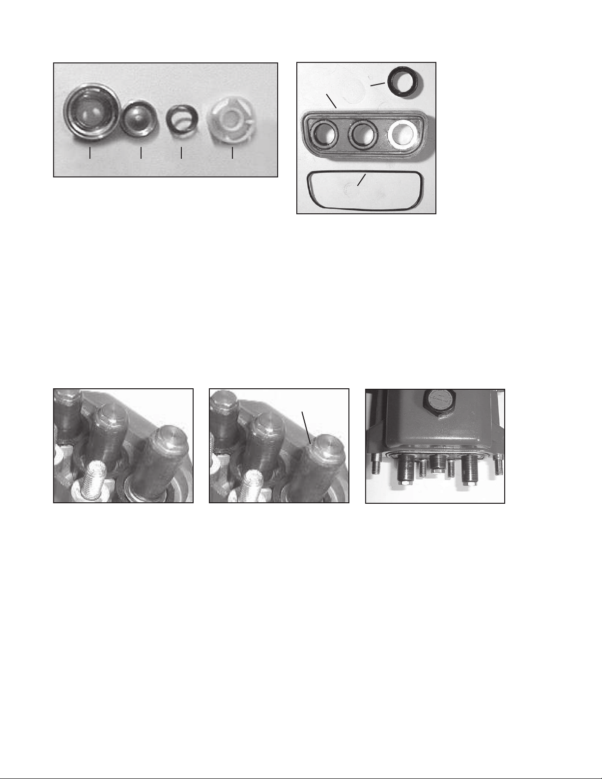
36 37 35 34
9. If pitted or worn, replace inlet valve seats (36),
valve plates (37), springs (35) and spring
retainers (34). Re-insert items 34-38 into valve
adapter (39). Install valve assembly (34-40) into
manifold (29). Reinstall manifold plugs (41) and
torque plugs to 52 ft.-lbs. (70 Nm).
48
50
49
10. The rear v-sleeve
housing (48) may be
removed by prying
evenly outward with a
fl at screwdriver. After
slipping housing over
ceramic plunger (24A),
inspect seals (50) and
o-ring (49) and replace
as necessary. If the
crankcase is to be disassembled, the housing
should not be replaced
until later.
11. Inspect ceramic plunger
(24A) tips for wear. If necessary, replacement of the
ceramic plungers may be
accomplished by removing
the plunger bolt assemblies
(24B and 24C) with a 13mm
wrench. Ceramic plungers should now slide off the
stainless steel plunger base
(22). Excessive resistance
to plunger removal may be
overcome by heating the
stainless steel plunger base.
This will melt any excess
loc-tite beneath the ceramic
plunger allowing easy removal.
24C
12. Replace copper ring (24C)
onto plunger bolt (24B). Slide
plunger bolt assembly into ceramic plunger (24A). Apply a
light fi lm of loc-tite to plunger
bolt threads and place plunger
assembly onto stainless steel
plunger base (22) and tighten
tension screw (24B) to 199
in.-lbs. (22.5 Nm).
13. To replace plunger oil seals
(26), proceed to “Gear End
Disassembly” section below.
Otherwise, continue as described below.
14. Before replacing pump
manifold (29), fi rst rotate
crankshaft (18) until two
outside plungers (24A)
extend evenly forward. Next
lubricate v-sleeves (50) in
the rear v-sleeve housing
(48) and slide housing over
plungers. Lubricate ceramic
plungers with a light fi lm of
oil. Carefully and evenly
slide manifold over plungers and press manifold
fi rmly against crankcase (1).
Replace manifold stud bolts
(45), washers (47) and nut
(46) and tighten to 35 ft.-lbs.
(47.5 Nm).
9
 Loading...