

Giant Factories UG50-65(-59), UG50-65, UG50-59 Owner's Manual Installation And Operating Instructions
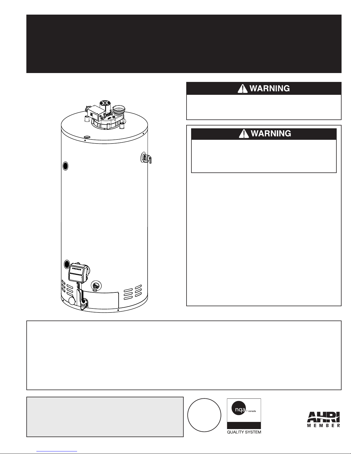
RESIDENTIAL POWER VENT GAS-FIRED WATER HEATERS
ISO 9001
ENREGISTRÉ
ISO 9001
REGISTRED
(EQUIPPED WITH FVIR TECHNOLOGY)
OWNER’S MANUAL
INSTALLATION AND OPERATING INSTRUCTIONS
UG50-65(-59) Model
This water heater IS NOT design certified for
installation in a manufactured (mobile) home or
for installation outdoors.
If the information in these instructions is not
followed exactly, a fire or explosion may
result causing property damage, personal
injury, or death.
DO NOT store or use gasoline or other
flammable vapours and liquids in the vicinity of
this or any other appliance.
WHAT TO DO IF YOU SMELL GAS
•DO NOT try to light any appliance.
•DO NOT touch any electrical switch,
DO NOT use any phone in your building.
•From a neighbour’s phone, immediately
call your gas supplier. Follow the gas
supplier’s instructions.
•If you cannot reach your gas supplier, call the
fire department.
Installation and service must be performed by
a qualified installer, service agency, or the gas
supplier.
IMPORTANT
READ THESE INSTRUCTIONS CAREFULLY BEFORE BEGINNING THE INSTALLATION. PROPER
INSTALLATION WILL PROVIDE SAFE AND EFFICIENT SERVICE, AND AVOID NEEDLESS EXPENSE NOT
COVERED BY THE WARRANTY. READ THE PRODUCT WARRANTY CONTAINED IN THIS MANUAL AND
REMEMBER TO FILL OUT AND RETURN TO THE MANUFACTURER ALL RELEVANT WARRANTY CARDS
AND CERTIFICATES. SHOULD YOU HAVE ANY QUESTIONS, PLEASE CONTACT YOUR LOCAL DEALER
OR REFER TO THE GETTING SERVICE FOR YOUR WATER HEATER SECTION OF THIS MANUAL.
SAVE THIS MANUAL FOR FUTURE REFERENCES.
For your records, write the model and serial number here:
Model # ________________________________
Serial # _________________________________
54000012
© 2012 Giant Factories Inc. Printed in Canada GI-IM015En-1112
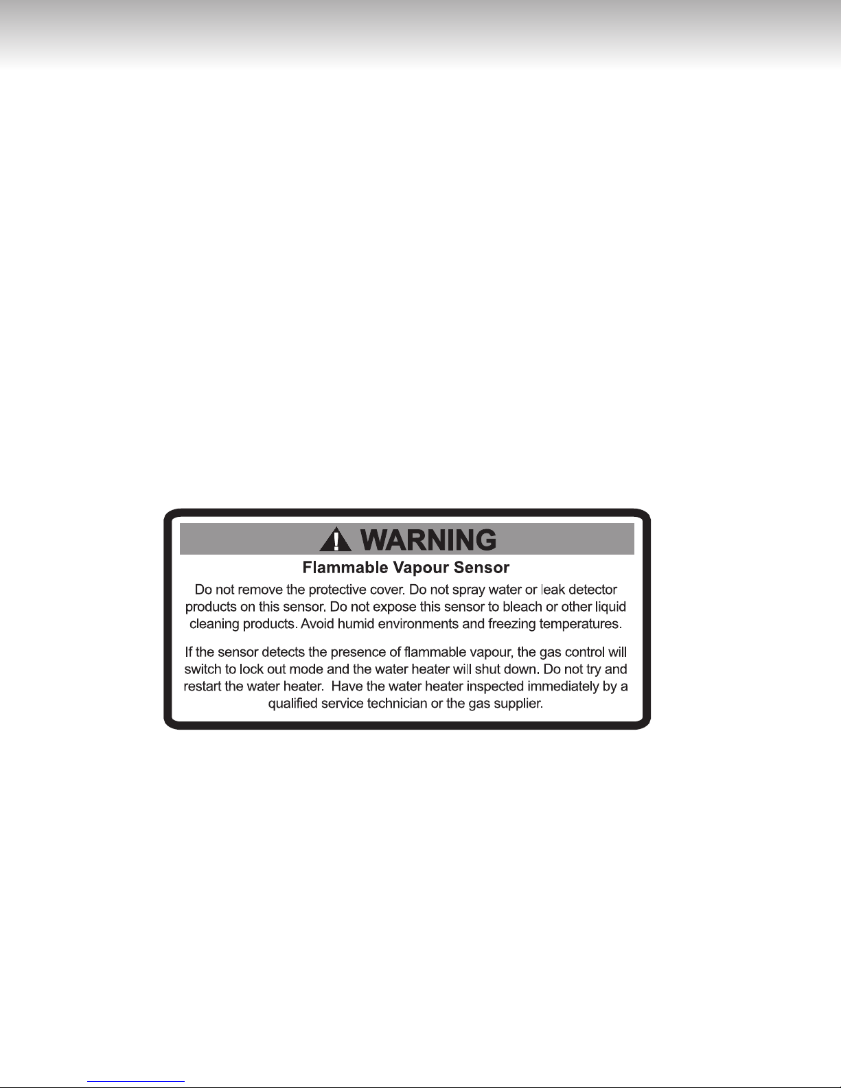
TABLE OF CONTENTS
Safety Information ............. 3
Installation Instructions
Location ................ 4
Minimum Clearances .......... 4
Combustion and Ventilation Air Supply .. 4
Requirements for Unconfined Spaces ... 5
Requirements for Confined Spaces .... 5
Louvers and Grilles ........... 6
Corrosive Atmospheres ......... 6
Venting ................. 7
Through-the-Wall Venting Installation ... 7
Through-the-Roof Venting Installation ... 8
Condensation in the Venting System ... 8
Installation of the venting system ..... 8
Water Piping .............. 8
Temperature & Pressure-Relief Valve .. 10
Pressure Build-up in a Water System .. 11
Filling the Water Heater ........ 11
Gas Connections ........... 11
Installation Instructions for
Water Heaters Approved for Space
Heating and Potable Water Heating . 12
.......... 4
Wiring ................ 12
Installation Checklist .......... 14
Operating Instructions
Lighting the Water Heater ....... 15
Water Temperature Regulation ..... 16
Out of Fuel .............. 17
General Maintenance
Housekeeping ............. 17
Safety System ............. 17
Condensation ............. 17
Burner Ignitor Assembly ........ 18
Water Heater Tank ........... 18
Temperature and Pressure-Relief Valve . 18
Venting System Inspection ....... 18
Anode rods .............. 18
Draining the Water Heater ....... 18
Vacation ................ 19
Getting Service for your Water Heater .. 19
Replacement Parts
Troubleshooting Guide
Warranty
................. 24
.......... 15
........... 17
............ 20
.......... 21
FVIR technology equipped with a flammable vapour sensor and the flame arrestor
This water heater is equipped with new FVIR technology. Activation of the FVIR technology occurs when
flammable vapours are drawn into the water heater. If the flammable vapour sensor detects the presence of
flammable vapours when the water heater is operating, the gas control will switch to lock out mode and the
water heater will shut down. If the water heater is not operating when the flammable vapours are detected, the
control will switch to lock out mode and prevent the water heater from lighting. If the flammable vapours enter the
combustion chamber and ignite, the flame arrestor will prevent these combustible vapours from igniting outside
of the water heater.
If flammable vapours are detected:
•DO NOT try to light any appliance.
• DO NOT touch any electrical switch, DO NOT use any phone in your building.
•From a neighbour’s phone, immediately call your gas supplier. Follow the gas supplier’s instructions.
•Ifyoucannotreachyourgassupplier,callthefiredepartment.
After the flammable vapours have been evacuated, contact a qualified service technician or the gas supplier to
have the water heater inspected immediately. Replacement of an FVIR technology equipped water
heater due to a flammable vapour shutdown is not covered under the terms of the Standard
Basic Limited Warranty.
2
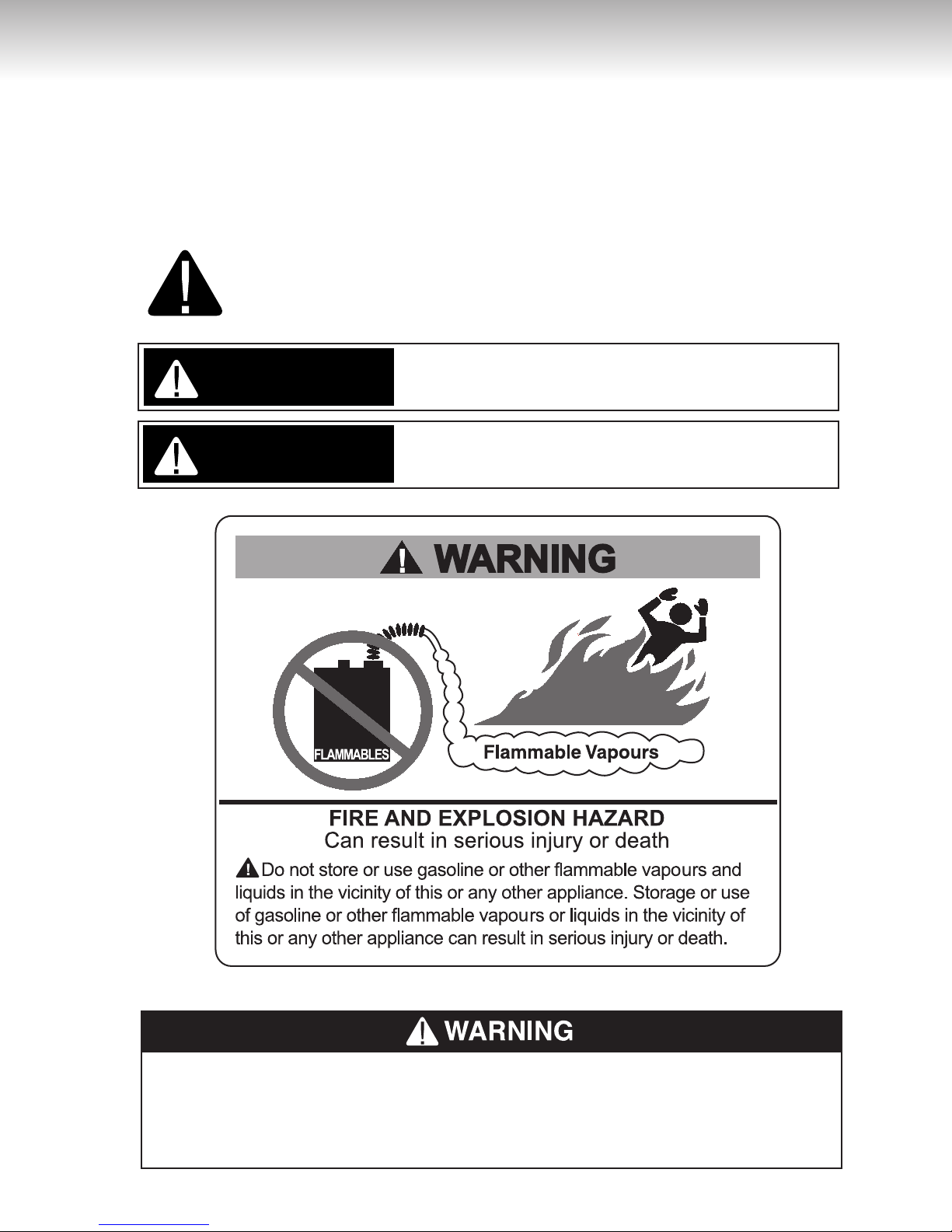
SAFETY INFORMATION
WARNING
Your safety and the safety of others is extremely important during the installation, operation, and servicing of this water heater. Many safety-related messages have been provided
in this manual and on your water heater. Always read and obey all safety messages. These
messages will point out the potential hazard, tell you how to reduce the risk of injury, and tell
you what will happen if the instructions are not followed.
This is the safety alert symbol. This symbol alerts you to potential hazards
that can kill or hurt you and others. All safety messages will follow the safety
alert symbol and either the word “DANGER” or “WARNING”.
Serious injury or death can occur if you do not
DANGER
WARNING
follow the instructions immediately.
Serious injury or death can occur if you do not
follow the instructions.
DO NOT use this water heater if any part has been under water. Immediately call a
qualified service technician to inspect the water heater and to replace any part of the
control system and any gas control which has been under water. Failure to follow this
instruction can result in property damage, personal injury, or death.
3
INSTALLATION INSTRUCTIONS
IMPORTANT
These instructions have been written as a guide for the proper installation and operation of your water heater,
and the manufacturer of this water heater will not accept any liability where these instructions have not been followed. However, for your safety and to avoid damage caused by improper installation, this water heater must be
installed by a Certified Licensed Professional, and meet all local codes or, in the absence of local codes, CAN/
CSA B149.1, Natural Gas and Propane Gas Installation Code, in Canada, and/or the National Fuel Gas Code,
ANSI Z223.1/NFPA 54, in the United States.
Before proceeding with the installation instructions:
1)
Inspect the water heater and its component parts for possible damage. DO NOT install or attempt to
repair any damaged component parts. If you detect any damage, contact the dealer where the water
heater was purchased or the manufacturer listed on the warranty card.
Verify that the type of gas being supplied corresponds to that which is marked on the rating plate and gas
2)
control valve of the water heater.
Location
This water heater should be located close enough to the
outside wall so that it is within the venting requirements
listed in these installation instructions and as close as
possible to the main use of hot water. This location must
not be subject to freezing temperatures. The water
heater should be positioned, so that there is easy
access to the burner, gas control valve, and drain
valve. It must be located close to a suitable free-flowing floor drain. Where a floor drain is not adjacent to
the water heater, a suitable drain pan must be installed
under the water heater (see Figure 10). This drain pan
should be at least four (4) inches (10.2 cm) larger than
the diameter of the water heater, and at least one
(1) inch (2.5 cm) deep, providing access to the drain
valve. This pan must not restrict the flow of ventilation
and combustion air. This pan must be piped to a suitable drain to prevent damage to property in the event
of a water leak from the piping, the relief valve, or the
water heater.
Sooner or later, all water heaters leak. The
manufacturer, based on national building codes,
has given the necessary instructions to prevent
damage to the building. Under no circumstances
is the manufacturer to be held liable for any water
damage, in connection with this water heater.
This water heater is approved for installation on either a
combustible or non-combustible floor. However, should
this water heater be installed directly on carpeting, the
carpeting must be protected by a wood or metal panel
beneath the water heater. This panel must extend at
least three (3) inches (7.6 cm) beyond the width and
depth of the water heater. Should the water heater be
installed in an alcove or closet, the entire floor area
must be covered by the panel.
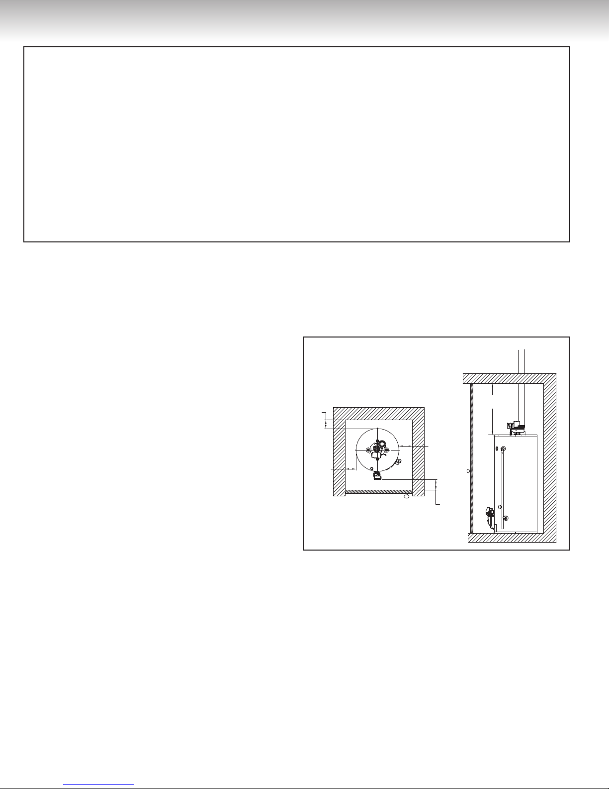
Minimum Clearances
The minimum clearances from combustible material
for this water heater are: Two (2) inches (5.1 cm) from
the sides and rear, four (4) inches (10.2 cm) from the
front, and eighteen (18) inches (45.7 cm) from the top
(see Figure 1).
Figure 1
18''
2''
min.
2''
min.
2''
min.
4''
min.
Combustion and Ventilation Air Supply
In order for the water heater to operate properly, it
must be supplied with an uninterrupted flow of clean
combustion and ventilation air. The area around the
water heater must always be kept clear and the combustion air intake holes at the bottom of the water
heater must never be blocked. An inadequate supply
of air to the water heater will produce a bright yellow
burner flame causing sooting in the combustion chamber, on the burner, and in the flue tube. This can result
in damage to the water heater and serious bodily
injury, if not corrected.
min.
4
INSTALLATION INSTRUCTIONS
Confined Space
Inlet air duct
18''
24''
Combustion and ventilation air requirements are determined by where the water heater is to be located.
Water heaters are installed in either open (unconfined)
spaces or smaller (confined) spaces, such as closets
or small rooms.
Requirements for Unconfined Spaces
An unconfined space is an area with at least 50 cubic
feet for each 1,000 BTUH (4.8 m
3
/kW) of the total
input rating for all gas appliances installed in that
space. Water heaters installed in unconfined spaces
do not usually require outdoor air to function properly.
However, in buildings with tight construction (heavy
insulation, vapour barriers, weather stripping, etc.),
and particularly in modern buildings, additional fresh
air may need to be provided. For instructions on
obtaining additional air supply, see the requirements
below for confined spaces.
Requirements for Confined Spaces
A confined space is an area where the volume is less
than 50 cubic feet for each 1,000 BTUH (4.8 m3/kW) of
the total input rating for all gas appliances installed in
that space. Water heaters installed in confined spaces
require additional air. This can be provided in two ways:
In Canada (refer to CAN/CSA B149.1)
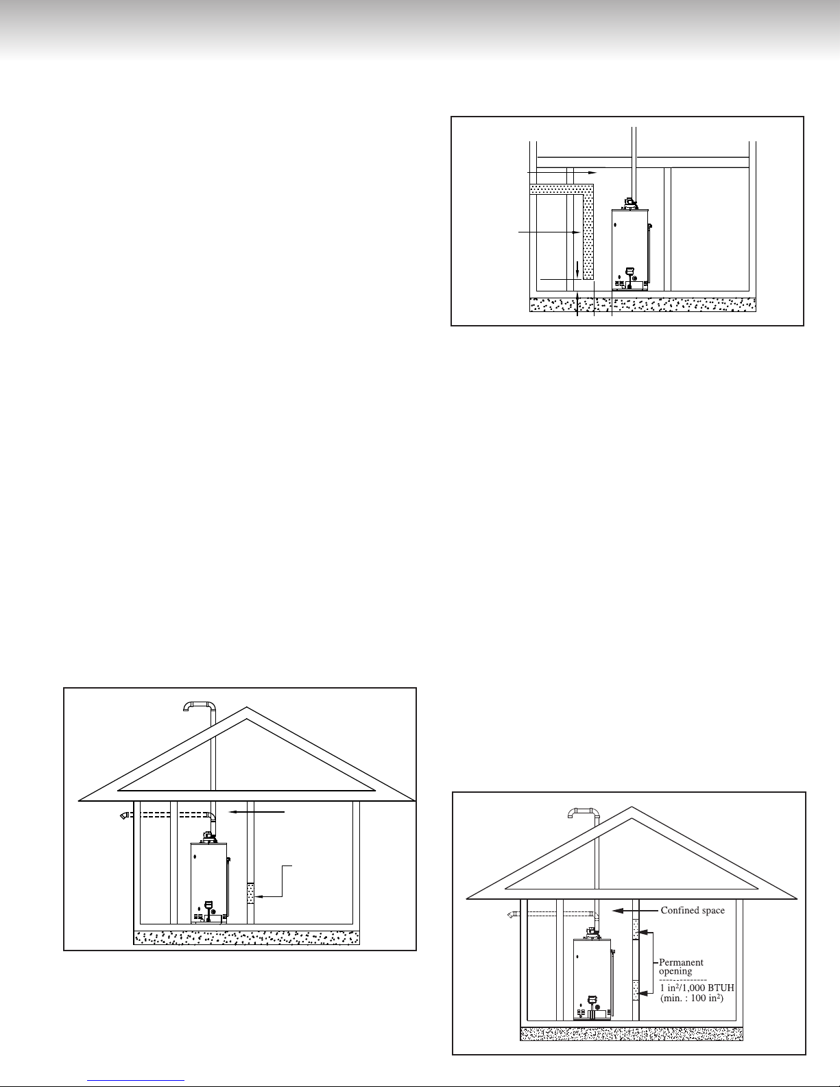
All Air From Inside the Building (see Figure 2):
1)
The confined space shall be provided with
one opening of one (1) square inch per 1,000 BTUH
(22.0 cm2/kW) communicating directly with one or
more rooms of sufficient volume, so that the combined volume of all spaces meets the criteria for an
unconfined space for all the appliances installed in
that confined space.
Figure 2
within two (2) feet horizontally from the burner level of
the appliance having the largest input.
Figure 3
Confined Space
Inlet air duct
18''
24''
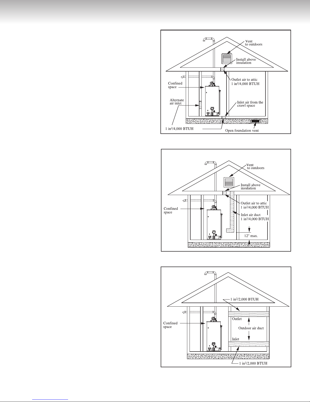
In U.S.A. (refer to ANSI Z223.1/NFPA 54)
1) All Air From Inside the Building (see Figure 4):
The confined space shall be provided with two per-
manent openings communicating directly with one or
more rooms of sufficient volume, so that the combined
volume of all spaces meets the criteria for an unconfined space. The total input rating of all gas appliances
installed in the combined space shall be considered in
making this determination.
Each opening shall have a minimum free area of one
(1) square inch per 1,000 BTUH (22.0 cm2/kW)
total input rating of all gas appliances in the confined
space, but not less than 100 square inches (645,16
cm2). One opening shall commence within six (6) inches
(15.2 cm) of the top and one within six (6) inches (15.2
cm) of the bottom of the enclosure.
2) All Air From Outdoors:
The confined space shall be provided with two perma-
nent openings, one commencing within six (6) inches
(15.2 cm) of the top and one commencing within six (6)
inches (15.2 cm) from the bottom of the enclosure.
The openings shall communicate directly or by ducts,
with the outdoors or spaces (crawl or attic) that freely
communicate with the outdoors.
of the
All Air From Outdoors: (see Figure 3):
2)
An air-supply shall be provided with one opening that
communicates directly with the outdoors by means of
a duct. This duct shall be sized according to CAN/CSA
B149.1 and terminate within one (1) foot above and
Confined Space
Permanent
Opening
-------------1 square inches /
1,000 BTUH
Figure 4
5
INSTALLATION INSTRUCTIONS
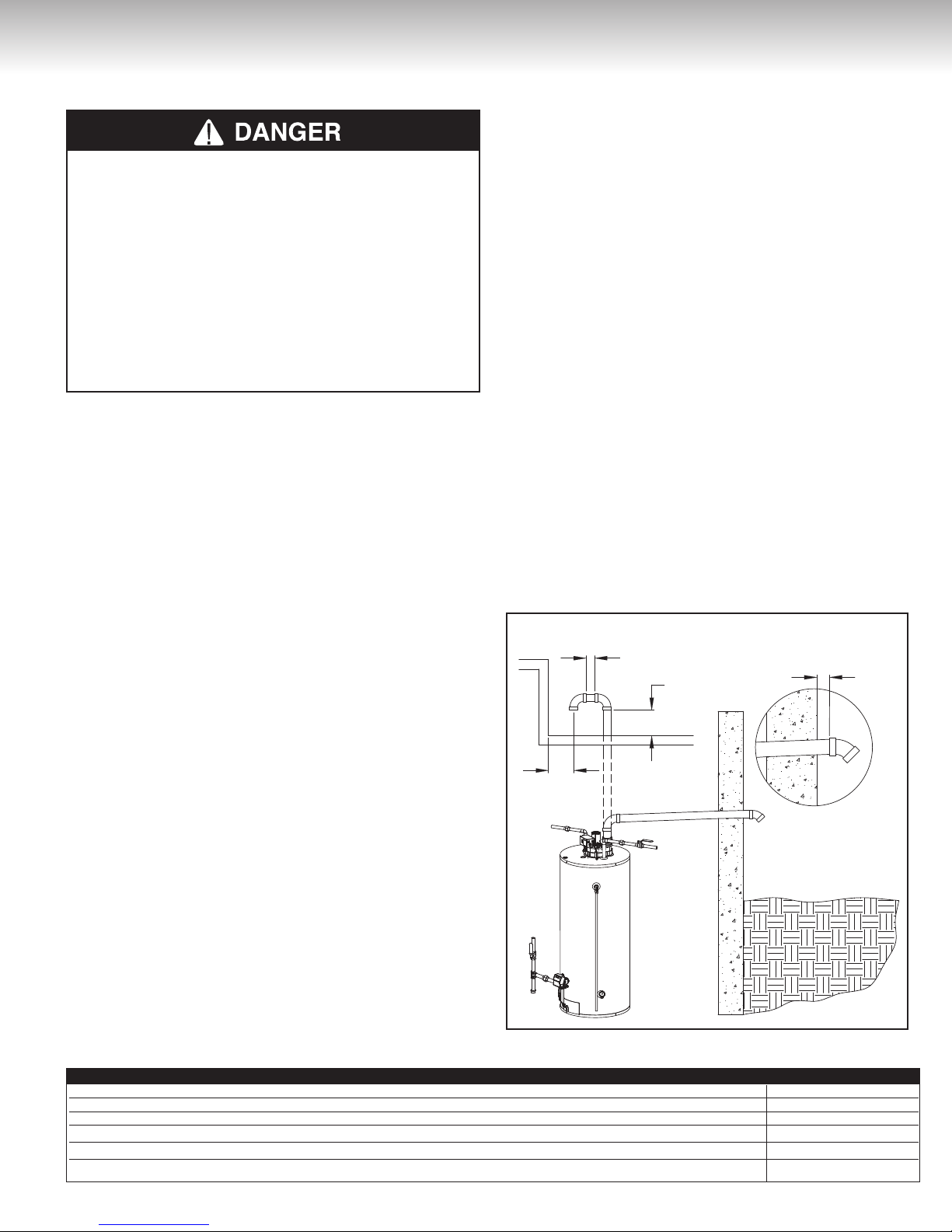
A) When communicating directly with the outdoors,
each opening shall have a minimum free area of one
(1) square inch per 4,000 BTUH (5.5 cm2/kW) of the
total input rating of all gas appliances in the enclosure
(see Figure 5).
B) When communicating with the outdoors through
vertical ducts, each opening shall have a minimum
free area of one (1) square inch per 4,000 BTUH
(5.5 cm2/kW) of the total input rating of all gas appliances in the enclosure (see Figure 6).
C) When communicating with the outdoors through
horizontal ducts, each opening shall have a minimum free area of one (1) square inch per 2,000
BTUH (11.0 cm2/kW) of the total input rating of
all gas appliances in the enclosure (see Figure 7).
When ducts are used, they shall be of the same
cross-sectional area as the free area of the openings to
which they connect. The minimum short side dimension
of rectangular air ducts shall not be less than three (3)
inches (7.62 cm).
Louvers and Grilles
In calculating free area for ventilation and combustion air supply openings, consideration must be
given to the blocking effect of louvers, grilles, or
screens protecting the openings. Screens must not
be smaller than 1/4 inch (6.4 mm) mesh. If the free
area through a particular design of louver or grille
is known, it should be used in calculating the size
of opening required to provide the free area specified. If the design and free area is not known, it may
be assumed that wood louvers and grilles will allow
20-25% free area and metal louvers and grilles will
allow 60-75% free area. Louvers and grilles must
be installed in the open position or interconnected with the water heater so that they are opened
automatically during water heater operation.
Figure 5
Figure 6
Figure 7
Corrosive Atmospheres
If this water heater is to be installed in a beauty shop,
barber shop, photo processing lab, dry cleaning
establishment, a building with an indoor pool, or
near a chemical storage area, it is imperative that
the combustion and ventilation air be drawn from
outside these areas. These particular environments
contain products such as aerosol sprays, detergents,
bleaches, cleaning solvents, refrige rants, and other
volatile compounds that, in addition to being highly
flammable, become highly corrosive acid compounds
when burned. Exposure to such compounds can be
hazardous and lead to premature product failure.
Should the water heater fail, due to exposure to
such a corrosive atmosphere, the warranty is void.
6
INSTALLATION INSTRUCTIONS
Venting
When installing the venting system, make sure to
follow all local codes or, in the absence of local
codes, CAN/CSA B149.1, Natural Gas and
Propane Gas Installation Code, in Canada, and/
or the National Fuel Gas Code, ANSI Z223.1/
NFPA 54, in the United States. Never operate the
water heater unless it is properly ventilated to the
outdoors and has adequate air supply for proper
operation. Failure to properly install the venting
system could result in property damage, personal
injury, or death.
Before installing the vent piping, make sure that the
vent system layout has been properly planned. Verify
that the location of the water heater respects all
clearances from combustible material, all venting
requirements (see Table 1), and that the vent terminal
will be installed as specified by all local codes or, in
the absence of local codes, CAN/CSA B149.1, Natural
Gas and Propane Installation Code, in Canada, and/or
the National Fuel Gas Code, ANSI Z223.1/NFPA 54, in
the United States (see Figure 9).
According to the CAN/CSA-B149, Natural Gas and
Propane Installation Code, plastic vent systems installed
in Canada must be certified to the STANDARD FOR
TYPE BH GAS VENTING SYSTEMS, ULC S636.
Components of the certified vent system must not be
interchanged with other vent systems or unlisted pipe/
fittings. Plastic components and specified primers and
glues of the certified vent system must be from a single
vent system manufacturer and not intermixed with other
vent system manufacturer’s vent system parts unless
those are certified to be used with this system. Plastic
vent systems shall also be installed such that the first
three (3) feet (91 cm) of pipe from the water heater outlet
is readily accessible for visual inspection.
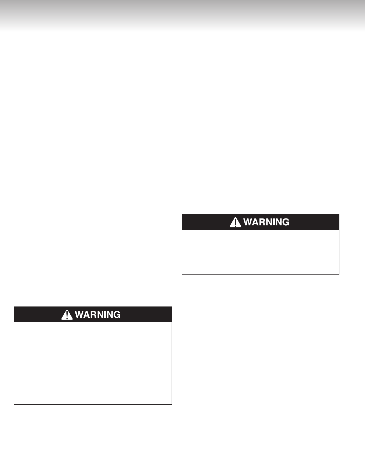
Through-the-Wall Venting Installation
Cut or drill a hole through the exterior wall, slightly
larger than the diameter of the vent pipe selected. The
larger hole will allow for final alignment with the water
heater. Extend a section of pipe through the hole to
the outside and attach the terminating elbow to the
exterior end of the pipe. Connect and secure all piping
and elbows from the power venter to the wall. Make
sure that all horizontal runs have a minimum rise of 1/4
inch per foot (21 mm/m) of run (see Figure 8).
This water heater is equipped with a power venter
that evacuates the products of combustion to the
outdoors. All models are shipped from the factory
with the power venter already installed.
Figure 8
3'' min.
18'' min.
2" min.
This water heater must be vented directly to the outdoors, either horizontally through the wall or vertically
through the roof. The venting must not be attached to
an existing chimney, or in common with any other appliance, and must not be insulated. Only three (3) inch (7.6
18'' min.
1/4"/foot
(21mm/m)
cm) schedule 40 PVC or CPVC, pipe and fittings may
be used to vent this water heater. The pipe and all the
fittings must be permanently joined using the appropriate primer and solvent-based cement. Horizontal
runs of vent pipe must be supported every three (3)
feet (91 cm) and vertical runs of vent pipe must be
supported every five (5) feet (1.5 m).
Table 1
UG50-65(-59)
PIPE VENT DIAMETER 3 inch
Maximum length plus one 45o or 90o termination elbow 50.0 feet (15.2 m)
Minimum length plus one 90o elbow and plus one 45o termination elbow 2.5 feet (0.8 m)
One 45o radius elbow is equivalent, in straight pipe, to 4.0 feet (1.2 m)
One 90o radius elbow is equivalent, in straight pipe, to 7.0 feet (2.1 m)
MAXIMUM EQUIVALENT LENGTH OF PIPE — DO NOT EXCEED MAXIMUM LENGTH OF PIPE
7
INSTALLATION INSTRUCTIONS
When the installation is completed, the vent terminal
must be a minimum of two (2) inches (5.1 cm) from the
exterior surface of the wall (see Figure 8). Make sure
that all piping is properly braced. If the venting will
pass through an enclosed area, make sure to leave
at least one (1) inch (2.5 cm) clearance around the
piping for air circulation.
Through-the-Roof Venting Installation
Cut or drill a hole through the roof and ceiling, slightly
larger than the diameter of the vent pipe selected.
The larger hole will allow for final alignment with the
water heater. Construct the vent terminal assembly.
Extend a section of pipe through the hole in the roof
to the outside and attach the terminal assembly to the
exterior end of the pipe. Connect and secure all piping
and elbows from the power venter to the roof. Make
1
sure that all horizontal runs have a minimum rise of
inch per foot (21 mm/m) of run (see Figure 8). When
the installation is completed, the vent terminal must
be a minimum of eighteen (18) inches (45.7 cm) from
the exterior surface of the roof (see Figure 8). Make
sure that all piping is properly braced. If the venting
will pass through an enclosed area, make sure to
leave at least one (1) inch (2.5 cm) clearance around
the piping for air circulation.
Condensation in the Venting System
In some installations, condensation will form in the
horizontal runs of vent piping. To prevent condensation from flowing back into the power venter, install a
condensate trap just past the first elbow of the vent
piping system. Make sure that the condensate removal tube flows to a suitable free-flowing drain.
Installation of the venting system
ALWAYS read and obey all safety messag-
es printed on the primer, cleaner, and cement
containers. Primer, cleaner, and cements are
extremely flammable. DO NOT store these products near heat, sparks, or flames. They are
harmful or fatal if swallowed. Their vapours are
also harmful. They may irritate eyes and can be
absorbed through the skin. Failure to follow these
instructions can result in property damage, personal injury, or death.
1) Adjust the vent pipe length to properly fit the vent system adaptor on the blower assembly outlet.
2) Cut pipe ends squarely, removing all burrs and dirt.
3) Dry fit the pipe/fitting to be connected to make sure
they fit properly.
4) Clean the pipe/fitting with the proper primer or cleaner.
/4
5) Apply a thin coat of cement to the fitting, avoiding puddling inside.
6) Apply a liberal coat of cement to the vent pipe, leaving
no voids.
7) QUICKLY assemble parts while cement is fluid! If you
wait too long, re-coat pipe/fitting.
8) Push the vent pipe completely into the PVC coupling,
turning as it goes until it bottoms out.
9) Hold pipe and fitting together for 30 seconds. Then
carefully clean off any excess material with a cloth.
Allow connections a sufficient time to cure before disturbing.
10) Loosen the upper hose clamp on the rubber transition fitting and fully insert the CPVC pipe of the vent
system adaptor (1.25” deep). Do not apply cement to
the rubber transition fitting.
11) Tighten the upper hose clamp to ensure the vent pipe
is firmly secured and gas tight.
12) Make sure that the lower hose clamp is firmly seated,
secured and gas tight. Gently move the vent pipe side
to side and vertically to ensure that it is securely in
place and that there is no slippage.
When the installation is complete, visually inspect the
venting system to make sure that all joints are properly connected and all instructions have been followed.
Failure to properly install the venting system could
result in property damage, personal injury, or death.
Water Piping
Refer to Figure 10 for a typical installation. Use of this
layout should provide a trouble-free installation for the
life of the water heater. Before making the plumbing
connections, locate the COLD water inlet and the
HOT water outlet. These fittings are both 3/4” N.P.T.
male thread. Make sure that the dip-tube is installed in
the cold water inlet. Install a shut-off valve close to the
water heater in the cold water line. It is recommended
that unions be installed in the cold and hot water lines
so that the water heater can be easily disconnected,
if servicing is required.
When assembling the hot and cold piping, use a
good food grade of pipe joint compound, and ensure
all fittings are tight. It is imperative that open flame is
not applied to the inlet and outlet fittings, as heat will
damage or destroy the plastic-lined fittings. This will
result in premature failure of the fittings, which is
not covered by the warranty.
8
 Loading...