

Giant Factories UG50-58, UG50-62 Installation And Operating Instructions Manual
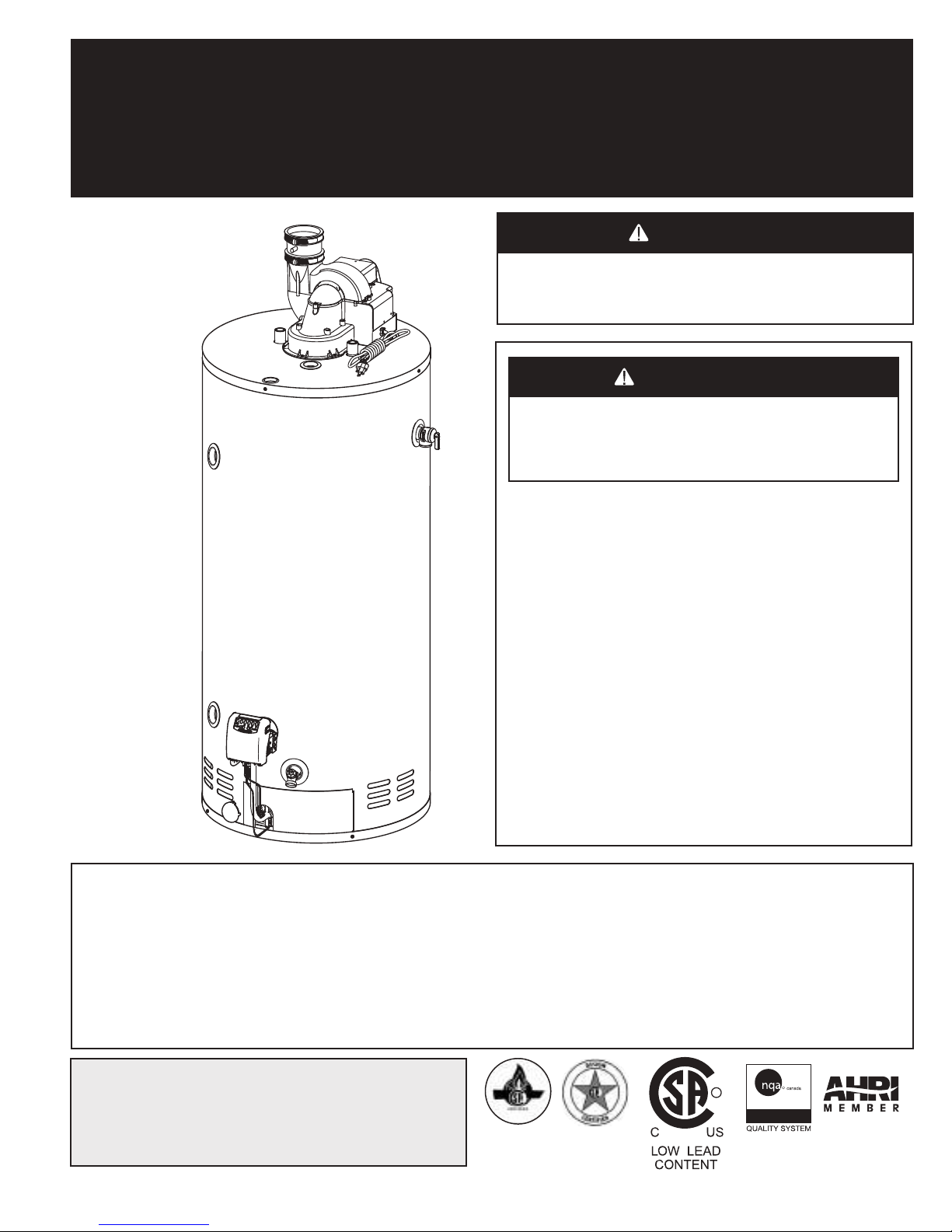
RESIDENTIAL GAS-FIRED POWER VENT WATER HEATERS
ISO 9001
ENREGISTRÉ
R
WARNING
CAUTION
WARNING
CAUTION
(EQUIPPED WITH FVIR TECHNOLOGY)
OWNER’S MANUAL
INSTALLATION AND OPERATING INSTRUCTIONS
UG50-62 (Nat) &
UG50-58 (LP) Models
High Input
This water heater IS NOT design certified for
installation in a manufactured (mobile) home or
for installation outdoors.
If the information in these instructions is not
followed exactly, a fire or explosion may result
causing property damage, personal injury, or
death.
DO NOT store or use gasoline or other
flammable vapours and liquids in the vicinity of
this or any other appliance.
WHAT TO DO IF YOU SMELL GAS
• DO NOT try to light any appliance.
• DO NOT touch any electrical switch.
• DO NOT use any phone in your building.
• From a neighbour’s phone, immediately
call your gas supplier. Follow the gas
supplier’s instructions.
• If you cannot reach your gas supplier, call the
fire department.
Installation and service must be performed by
a qualified installer, service agency, or the gas
supplier.
IMPORTANT
READ THESE INSTRUCTIONS CAREFULLY BEFORE BEGINNING THE INSTALLATION. PROPER
INSTALLATION WILL PROVIDE SAFE AND EFFICIENT SERVICE, AND AVOID NEEDLESS EXPENSE NOT
COVERED BY THE WARRANTY. READ THE PRODUCT WARRANTY CONTAINED IN THIS MANUAL AND
REMEMBER TO FILL OUT AND RETURN TO THE MANUFACTURER ALL RELEVANT WARRANTY CARDS
AND CERTIFICATES. SHOULD YOU HAVE ANY QUESTIONS, PLEASE CONTACT YOUR LOCAL DEALER OR
REFER TO THE GETTING SERVICE FOR YOUR WATER HEATER SECTION OF THIS MANUAL.
SAVE THIS MANUAL FOR FUTURE REFERENCES.
For your records, write the model and serial number here:
Model # _____________________________
Serial # _____________________________
54000060
© 2019 Giant Factories Inc. Printed in Canada GI-IM054En-0319
R
ISO 9001
REGISTRED

TABLE OF CONTENTS
Flammable Vapour Sensor
Do not remove the protective cover. Do not spray water or leak detector
products on this sensor. Do not expose this sensor to bleach or other liquid
cleaning products. A v oid humid en vironments and freezing temper atures.
If the sensor detects the presence of flammable vapours, the gas control will
switch to lock-out mode and the water heater will shut down. Do not try and
restart the water hea ter. Have the wa ter heater inspected immediately by a
qualified service technician or the gas supplier.
WARNING
!!
Safety Information ................ 3
Installation Instructions ............. 4
Altitude ....................4
Location ................... 4
Minimum Clearances ............. 4
Combustion and Ventilation Air Supply ..... 5
Requirements for Unconfined Spaces ...... 5
Requirements for Confined Spaces ....... 5
Louvers and Grilles .............. 6
Corrosive Atmospheres ............ 6
Venting .................... 7
Venting connection to the water heater .....7
Through-the-Wall Venting Installation ...... 9
Through-the-Roof Venting Installation ..... 11
Pipe Assembly ............... 11
Vent termination through-the-Wall ....... 11
Vent termination through-the-Roof. . . . . . . 12
Restrictor Screens .............. 12
Condensation in the Venting System ..... 13
Water Piping ................ 13
Temperature & Pressure-Relief Valve ..... 13
Pressure Build-up in a Water System ..... 13
Filling the Water Heater ........... 14
Gas Connections .............. 14
Installation Instructions for
Water Heaters Approved for Space
Heating and Potable Water Heating ...... 15
Wiring .................... 16
Installation Checklist ............. 17
Operating Instructions .............. 18
Operating the Water Heater .......... 18
Water Temperature Regulation ......... 19
Out of Fuel .................. 20
General Maintenance ............... 20
Housekeeping ................ 20
Safety System ................. 20
Condensation ................. 20
Burner Ignitor Assembly ............ 21
Temperature and Pressure-Relief Valve ..... 21
Venting System Inspection ........... 21
Anodes .................... 21
Draining the Water Heater ........... 22
Vacation ................... 22
Service Procedure ............... 22
Replacement Parts ................ 23
Troubleshooting Guide .............. 24
Model Dimensions ................ 27
Warranty ..................... 28
FVIR technology equipped with a flammable vapour sensor and a flame arrestor.
This water heater is equipped with the FVIR technology. Activation of the FVIR technology occurs when
flammable vapours are drawn into the water heater. If the flammable vapour sensor detects the presence of
flammable vapours when the water heater is operating, the gas control will switch to lock-out mode and the
water heater will shut down. If the water heater is not operating when the flammable vapours are detected, the
control will switch to lock-out mode and prevent the water heater from lighting. If the flammable vapours enter the
combustion chamber and ignite, the flame arrestor will prevent these combustible vapours from igniting outside
of the water heater.
If flammable vapours are detected:
• DO NOT try to light any appliance.
• DO NOT touch any electrical switch, DO NOT use any phone in your building.
• From a neighbour’s phone, immediately call your gas supplier. Follow the gas supplier’s instructions.
• If you cannot reach your gas supplier, call the fire department.
After the flammable vapours have been evacuated, contact a qualified service technician or the gas supplier to
have the water heater inspected immediately. Replacement of a FVIR technology equipped water
heater due to a flammable vapour shutdown is not covered under the terms of the Standard
Basic Limited Warranty.
2
SAFETY INFORMATION
DANGER
WARNING
CAUTION
WARNING
CAUTION
WARNING
CAUTION
Your safety and the safety of others is extremely important during the installation, operation
and servicing of this water heater. Many safety-related messages have been provided in
this manual and on your water heater. Always read and abide by all safety messages. These
messages will point out the potential hazard, tell you how to reduce the risk of injury and tell
you what will happen if the instructions are not followed.
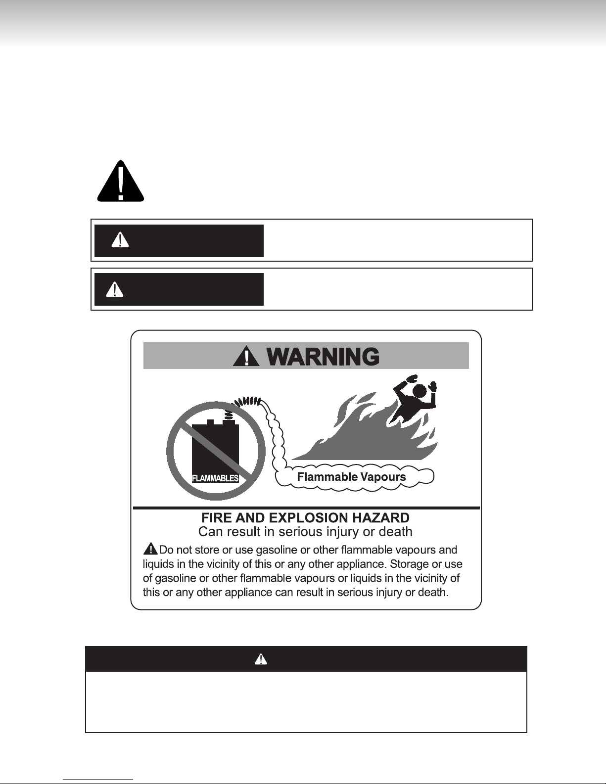
This is the safety alert symbol. This symbol alerts you to potential hazards
that can kill or hurt you and others. All safety messages will follow the safety
alert symbol and either the word “DANGER” or “WARNING”.
Serious injury or death can occur if you do not
follow the instructions immediately.
Serious injury or death can occur if you do not
follow the instructions.
DO NOT use this water heater if any part has been under water. Immediately call a
qualified service technician to inspect the water heater and to replace any part of the
control system and any gas control which has been under water. Failure to follow this
instruction can result in property damage, personal injury, or death.
32
WARNING
CAUTION
INSTALLATION INSTRUCTIONS
IMPORTANT
These instructions have been written as a guide for the proper installation and operation of your water heater,
and the manufacturer of this water heater will not accept any liability where these instructions have not been
followed. However, for your safety and to avoid damage caused by improper installation, this water heater must
be installed by a Certified Licensed Professional, and meet all local codes or, in the absence of local codes,
CSA B149.1, Natural Gas and Propane Gas Installation Code, in Canada, and/or the National Fuel Gas Code,
ANSI Z223.1/NFPA 54, in the United States.
Before proceeding with the installation instructions:
1) Inspect the water heater and its component parts for possible damage. DO NOT install or attempt to
repair any damaged component parts. If you detect any damage, contact the dealer where the water
heater was purchased or the manufacturer listed on the warranty card.
2) Verify that the type of gas being supplied corresponds to that which is marked on the rating plate and gas
control of the water heater.
Altitude
Input rating of this water heater is based on sea
level operation. At higher elevations the actual input
rate will be lower than the value listed on the rating
plate due to the natural derating of natural gas
and propane. This water heater can be installed at
elevation up to to 7,800 feet (2,377 m) without any
change or modification. Do not attempt to adjust the
input rate by changing the manifold pressure.
Failure to install a water heater suitable for the
altitude at the location it is intended to serve,
can result in improper operation of the appliance
resulting in property damage and/or producing
carbon monoxide gas, which could result in personal
injury or death.
Location
This water heater should be located close enough to the
outside wall so that it is within the venting requirements
listed in these installation instructions and as close as
possible to the main use of hot water. This location
must not be subject to freezing temperatures. The
water heater should be positioned, so that there is easy
access to the burner, gas control, and drain valve. It
must be located close to a suitable free-flowing floor
drain. Where a floor drain is not adjacent to the water
heater, a suitable drain pan must be installed under the
water heater (see Figure 10). In Canada, according to
the National Plumbing Code, this drain pan should be
at least two (2) inches (5.1 cm) larger than the diameter
of the water heater, and at least one (1) inch (2.5 cm)
deep, providing access to the drain valve. Local codes
may be more rigorous. This pan must not restrict the
flow of ventilation and combustion air. This pan must be
piped to a suitable drain to prevent damage to property
in the event of a water leak from the piping, the relief
valve, or the water heater.
Sooner or later, all water heaters leak. The
manufacturer, based on national building codes,
has given the necessary instructions to prevent
damage to the building. Under no circumstances
is the manufacturer to be held liable for any water
damage, in connection with this water heater.
This water heater is approved for installation on either
a combustible or non-combustible floor. However,
should this water heater be installed directly on
carpeting, such carpeting must be protected by a wood
or metal panel beneath the water heater. This panel
must extend at least three (3) inches (7.6 cm) beyond
the width and depth of the water heater. Should the
water heater be installed in an alcove or closet, the
entire floor area must be covered by the panel.
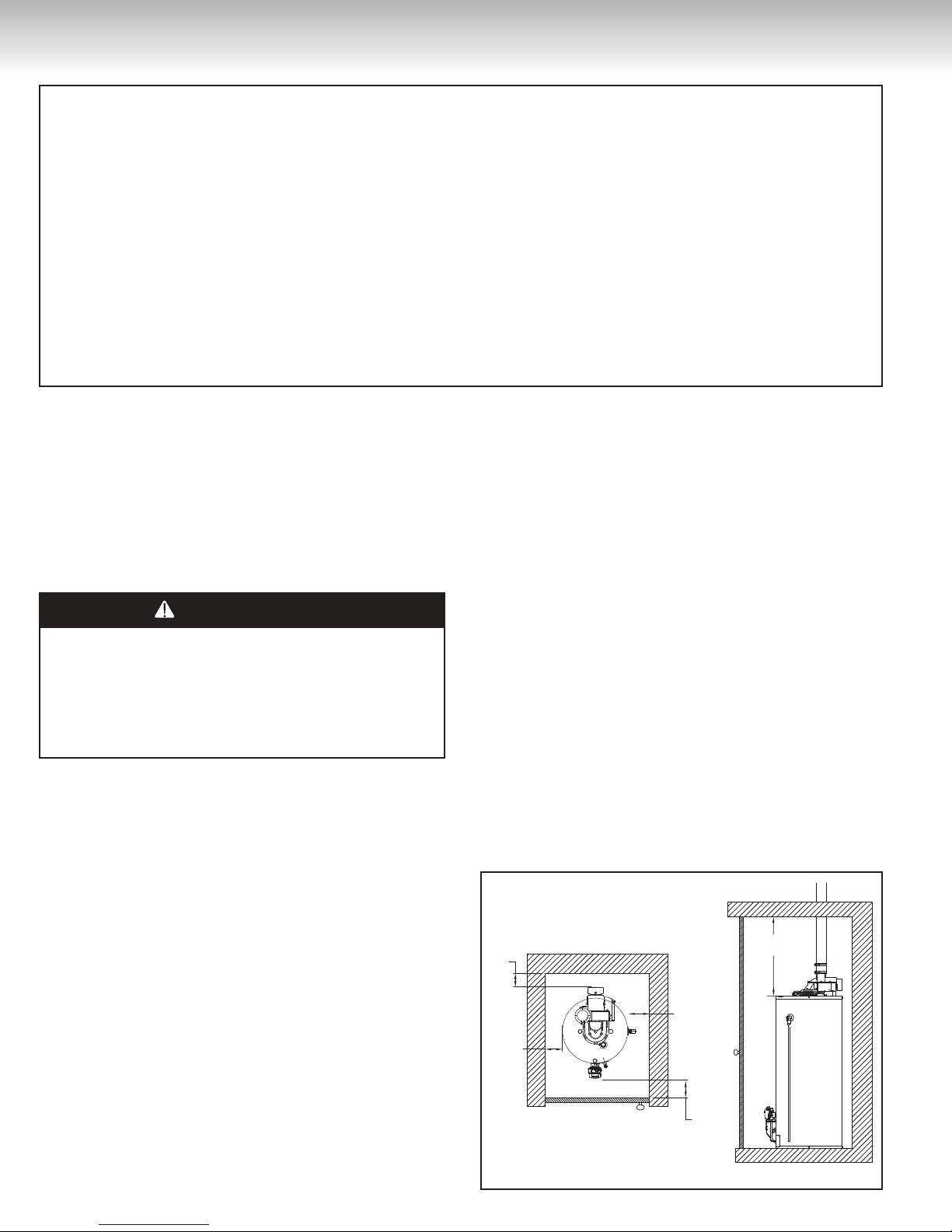
Minimum Clearances
The minimum clearances from combustible material
for this water heater are: Two (2) inches (5.1 cm) from
the sides and rear, four (4) inches (10.2 cm) from the
front, and eighteen (18) inches (45.7 cm) from the top
(see Figure 1).
Figure 1
18''
2''
min.
2''
min.
2''
min.
4''
min.
min.
4
Confined Space
Inlet air duct
18''
24''
INSTALLATION INSTRUCTIONS
Combustion and Ventilation Air Supply
In order for the water heater to operate properly, it
must be supplied with an uninterrupted flow of clean
combustion and ventilation air. The area around
the water heater must always be kept clear and the
combustion air intake holes at the bottom of the water
heater must never be blocked. An inadequate supply
of air to the water heater will produce a bright yellow
burner flame causing sooting in the combustion
chamber, on the burner, and in the flue tube. This
can result in damage to the water heater and serious
bodily injury, if not corrected.
Combustion and ventilation air requirements are
determined by where the water heater will be located.
Water heaters are installed in either open (unconfined)
spaces or smaller (confined) spaces, such as closets
or small rooms.
Requirements for Unconfined Spaces
An unconfined space is an area with at least fifty
(50) cubic feet for each 1,000 Btuh (4.8 m3/kW) of
the total input rating for all gas appliances installed
in that space. Water heaters installed in unconfined
spaces do not usually require outdoor air to function
properly. However, in buildings with tight construction
(heavy insulation, vapour barriers, weather stripping,
etc.), and particularly in modern buildings, additional
fresh air may need to be provided. For instructions on
obtaining additional air supply, see the requirements
below for confined spaces.
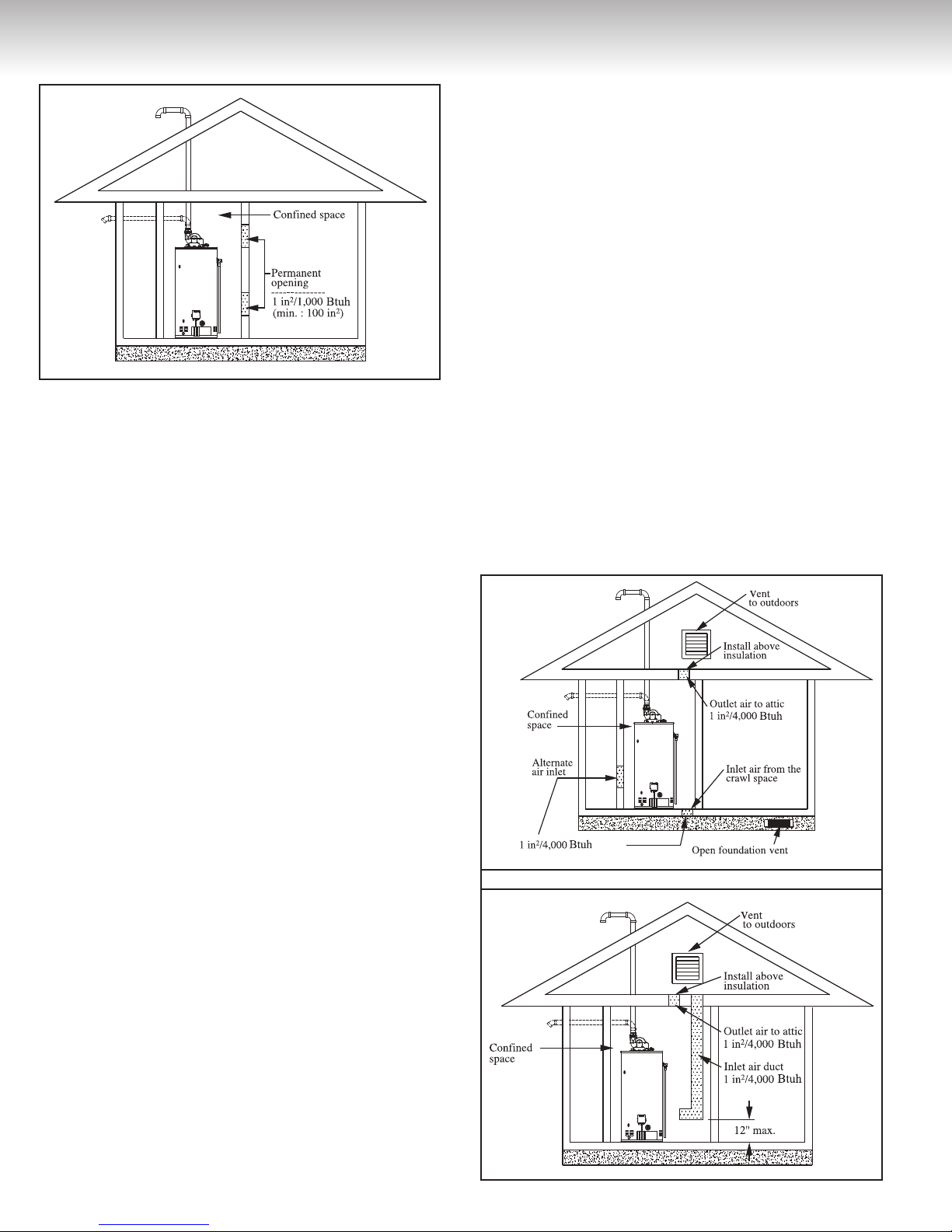
Figure 2
Confined Space
Permanent
Opening
-------------1 square inch /
1,000 Btuh
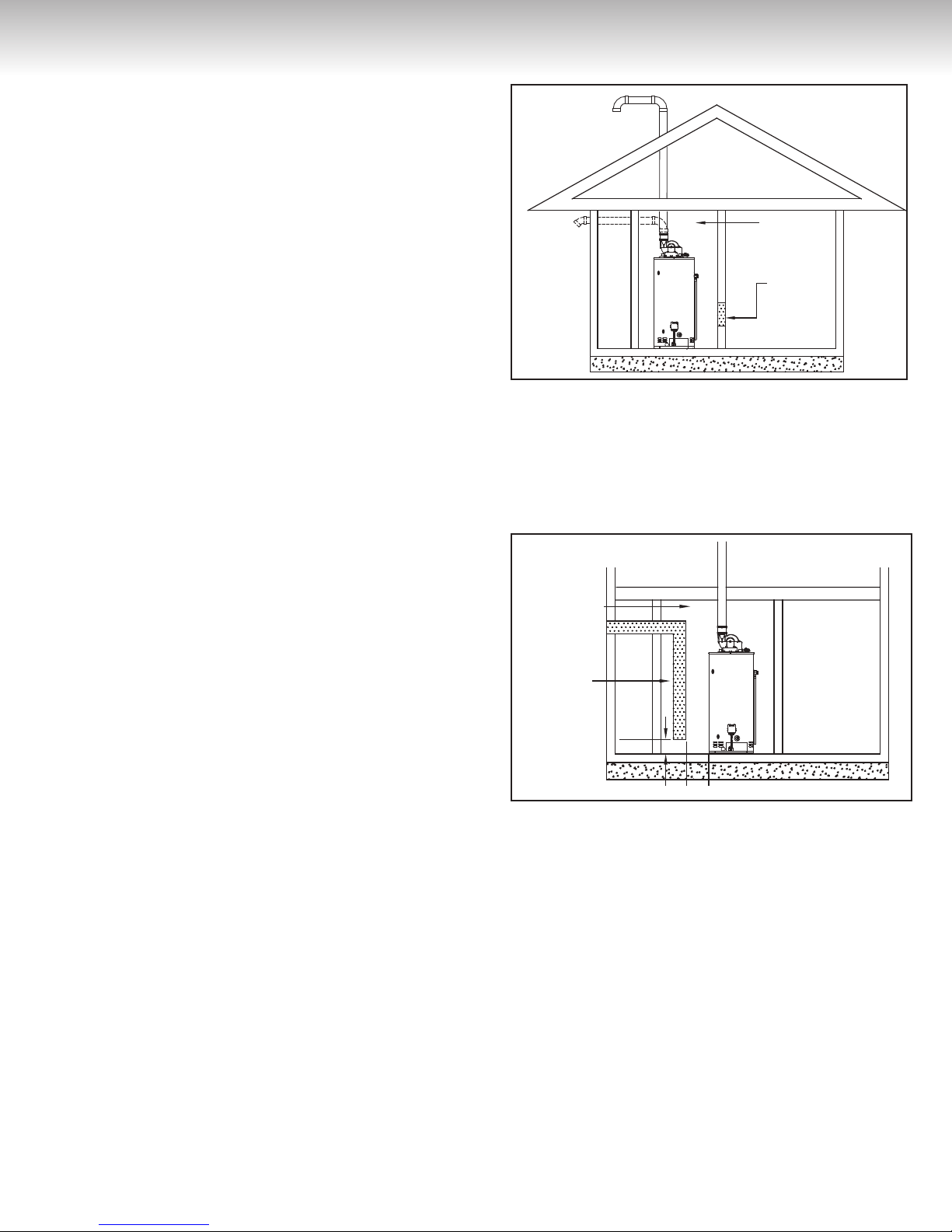
2) All Air From Outdoors: (see Figure 3):
An air supply shall be provided with one opening that
communicates directly with the outdoors by means of a
duct. This duct shall be sized according to CSA B149.1
and terminate within one (1) foot (30.5 cm) above and
within two (2) feet (61 cm) horizontally from the burner
level of the appliance having the largest input.
Figure 3
Confined Space
Inlet air duct
Requirements for Confined Spaces
A confined space is an area where the volume is less
than fifty (50) cubic feet for each 1,000 Btuh (4.8 m3/
kW) of the total input rating for all gas appliances
installed in that space. Water heaters installed in
confined spaces require additional air. This can be
provided in two ways:
In Canada (refer to CSA B149.1)
1) All Air From Inside the Building (see Figure 2):
The confined space shall be provided with one
opening of one (1) square inch per 1,000 Btuh
(22.0 cm2/kW) communicating directly with one
or more rooms of sufficient volume, so that the
combined volume of all spaces meets the criteria for
an unconfined space for all the appliances installed
in that confined space.
54
18''
24''
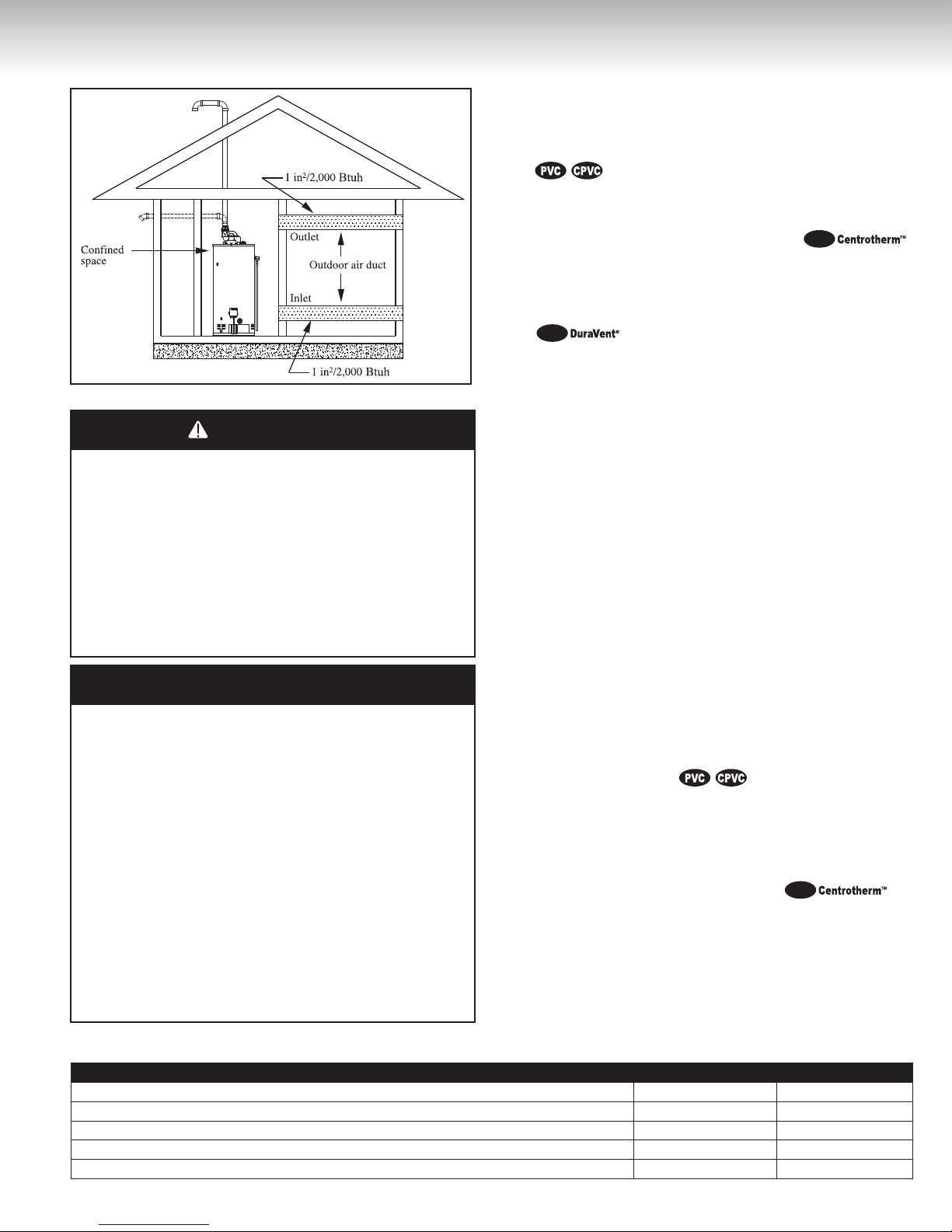
In U.S.A. (refer to ANSI Z223.1/NFPA 54)
1)
All Air From Inside the Building (see Figure 4):
The confined space shall be provided with two (2)
permanent openings communicating directly with
one or more rooms of sufficient volume, so that the
combined volume of all spaces meets the criteria for
an unconfined space. The total input rating of all gas
appliances installed in the combined space shall be
considered.
Each opening shall have a minimum free area of one
(1) square inch per 1,000 Btuh (22.0 cm2/kW) of the
total input rating of all gas appliances in the confined
space, but not less than one hundred (100) square
inches (645.16 cm2). One opening shall commence
within twelve (12) inches (30.5 cm) of the top and one
within twelve (12) inches (30.5 cm) of the bottom of
the enclosure.
INSTALLATION INSTRUCTIONS
Figure 4
2) All Air From Outdoors:
The confined space shall be provided with two (2)
permanent openings, one commencing within twelve
(12) inches (30.5 cm) of the top and one commencing
within twelve (12) inches (30.5 cm) from the bottom
of the enclosure. The openings shall communicate
directly or by ducts, with the outdoors or spaces
(crawl or attic) that freely communicate with the outdoors.
to provide the free area specified. If the design and
free area is not known, it may be assumed that wood
louvers and grilles will allow 20-25% free area and
metal louvers and grilles will allow 60-75% free area.
Louvers and grilles must be installed in the open
position or interconnected with the water heater so
that they are opened automatically during water
heater operation.
Corrosive Atmospheres
If this water heater is to be installed in a beauty shop,
barber shop, photo processing lab, dry cleaning
establishment, a building with an indoor pool, or
near a chemical storage area, it is imperative that
the combustion and ventilation air be drawn from
outside these areas. These particular environments
contain products such as aerosol sprays, detergents,
bleaches, cleaning solvents, refrige rants, and other
volatile compounds that, in addition to being highly
flammable, become highly corrosive acid compounds
when burned. Exposure to such compounds can be
hazardous and lead to premature product failure.
Should the water heater fail, due to exposure to
such a corrosive atmosphere, the warranty is void.
A) When communicating directly with the outdoors,
each opening shall have a minimum free area of
one (1) square inch per 4,000
of the total input rating of all gas appliances in the
enclosure (see Figure 5).
B) When communicating with the outdoors through
vertical ducts, each opening shall have a minimum
free area of one (1) square inch per 4,000
(5.5 cm2/kW) of the total input rating of all gas
appliances in the enclosure (see Figure 6).
C) When communicating with the outdoors through
horizontal ducts, each opening shall have a minimum
free area of one (1) square inch per 2,000 Btuh
(11.0 cm2/kW) of the total input rating ofall gas
appliances in the enclosure (see Figure 7).
When ducts are used, they shall be of the same crosssectional area as the free area of the openings to
which they connect. The minimum short side dimension
of rectangular air ducts shall not be less than three
(3) inches (7.6 cm).
Louvers and Grilles
In calculating free area for ventilation and combustion
air supply openings, consideration must be given
to the blocking effect of louvers, grilles, or screens
protecting the openings. Screens must not be smaller
than 1/4 inch (6.4 mm) mesh. If the free area through a
particular design of louver or grille is known, it should
be used in calculating the size of opening required
Btuh
(5.5 cm2/kW)
Btuh
Figure 5
Figure 6
6
DANGER
WARNING
CAUTION
PolyPro
®
PolyPro
®
INSTALLATION INSTRUCTIONS
The water might be vented using one of the following
Figure 7
Venting
When installing the venting system, make sure to
follow all local codes or, in the absence of local
codes, CSA B149.1, Natural Gas and Propane Gas
Installation Code, in Canada, and/or the National
Fuel Gas Code, ANSI Z223.1/NFPA 54, in the United
States. Never operate the water heater unless it is
properly ventilated to the outdoors and has adequate
air supply for proper operation. Failure to properly
install the venting system could result in property
damage, personal injury, or death.
IMPORTANT
According to the CSA B149.1, Natural Gas and
Propane Gas Installation Code, plastic venting systems
installed in Canada must be certified ‘‘STANDARD
FOR TYPE BH GAS VENTING SYSTEMS ULC
S636’’. Components of the certified venting system
must not be interchanged with other venting systems or
unlisted pipe/fittings. Plastic components and specified
primers and glues of the certified venting system must
be from a single venting system manufacturer and not
intermixed with other venting system manufacturer’s
venting system parts unless those are certified to
be used with this system. Plastic venting systems
shall also be installed such that the first three (3) feet
(91 cm) of pipe from the water heater outlet are readily
accessible for visual inspection.
options only:
• Three (3) inch (7.6 cm) or four (4) inch (10.2 cm)
schedule 40 PVC or CPVC, pipe and fittings.
•
Three (3) inch (7.6 cm) or four (4) inch (10.2 cm)
CentrothermTM polypropylene rigid pipe and fittings.
®
(InnoFlue® single-wall vent system).
InnoFlue
• Three (3) inch (7.6 cm) or four (4) inch (10.2 cm)
DuraVent® polypropylene rigid pipe and
fittings. (PolyPro® single-wall gas vent system).
®
PolyPro
Before installing the vent piping, make sure that the
venting system layout has been properly planned.
Verify that the location of the water heater respects
all clearances from combustible material, all venting
requirements (see Table 1), and that the vent terminal
will be installed as specified by all local codes or, in
the absence of local codes, CSA B149.1, Natural Gas
and Propane Installation Code, in Canada, and/or the
National Fuel Gas Code, ANSI Z223.1/NFPA 54, in
the United States (see Figure 11).
This water heater is equipped with a power venter that
evacuates the products of combustion to the outdoors.
All models are shipped from the factory with the power
venter already installed. This water heater must be
vented directly to the outdoors, either horizontally
through the wall or vertically through the roof. The
venting must not be attached to an existing chimney,
or in common with any other appliance, and must not
be insulated.
Venting connection to the water heater
PVC or CPVC PIPES:
The PVC or CPVC pipe must be inserted directly into
the rubber transition fitting on the blower assembly
outlet (see Figure 9).
CENTROTHERM™ POLYPROPYLENE PIPE
®
(InnoFlue® single-wall vent system):
InnoFlue
Use the special appliance adaptor from CentrothermTM
and insert it in the rubber transition fitting on the blower
assembly outlet. Refer to Table 2 and Figure 9a for
proper part number from CentrothermTM. On the four
(4) inch (10.2 cm) vent pipe, an increaser is necessary.
Table 1
MAXIMUM EQUIVALENT LENGTH OF PIPE — DO NOT EXCEED
PIPE VENT DIAMETER 3 inches (7.6 cm) 4 inches (10.2 cm)
Maximum length plus one 45-degree termination elbow 50.0 feet (15.2 m) 180.0 feet (54.9 m)
Minimum length plus one 90-degree elbow and plus one 45-degree termination elbow 2.5 feet (0.8 m) 50 feet (15.2 m)
One 45-degree radius elbow is equivalent, in straight pipe, to 4.0 feet (1.2 m) 4.0 feet (1.2 m)
One 90-degree radius elbow is equivalent, in straight pipe, to 7.0 feet (2.1 m) 8.0 feet (2.4 m)
* Note: Outdoor termination elbow not to be counted when determining total length.
76
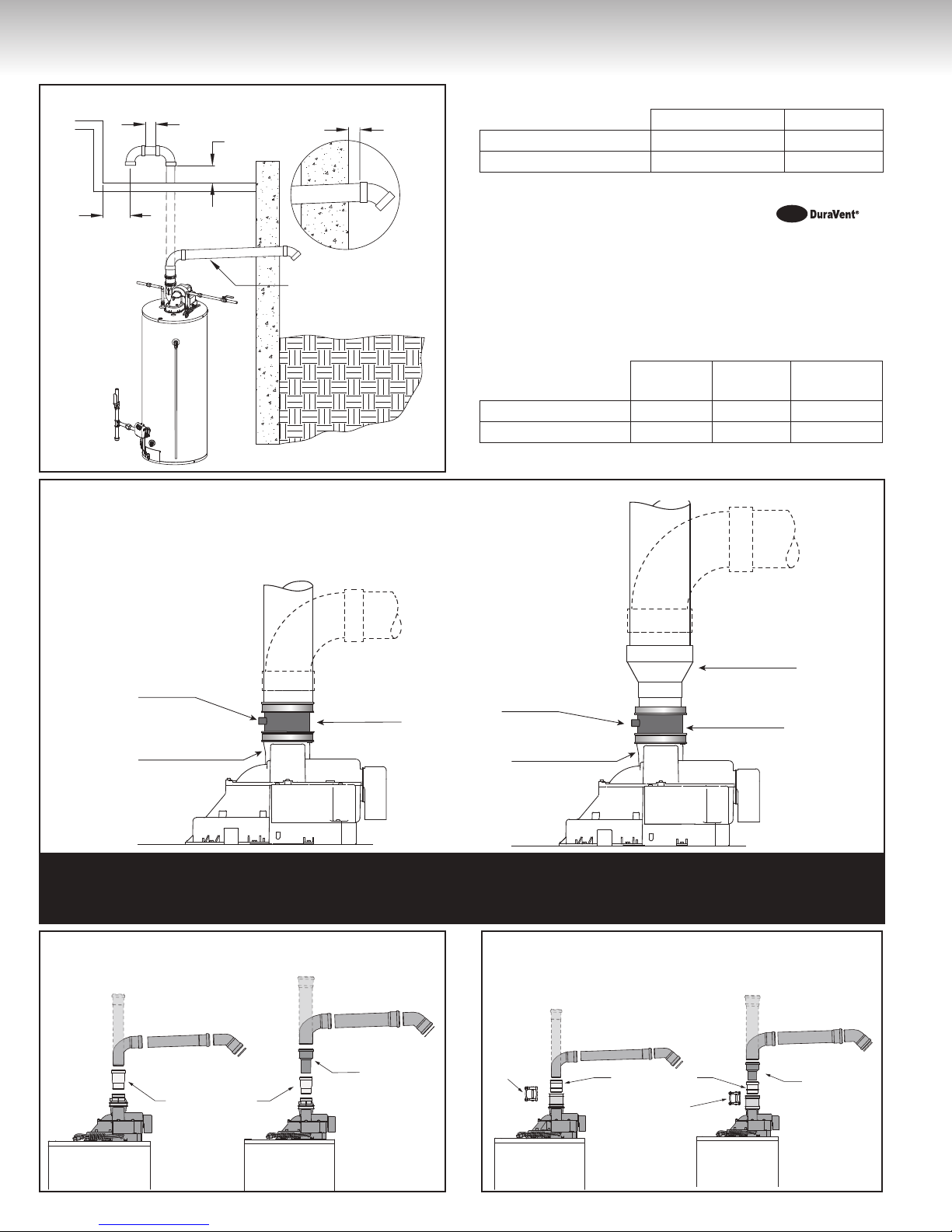
INSTALLATION INSTRUCTIONS
3” venting
4” venting
Appliance adaptor
Appliance
Adaptor
Clamp
Appliance
Adaptor Clamp
Increaser
Figure 8
18'' min.
Figure 9
Connection
to a 3-inch (7.6 cm)
vent system
3'' min.
18'' min.
2"
1/4”/foot (21 mm/m)
or as per manufacturer
specifications
Table 2 — Centrotherm™
Appliance adapter Increaser
3-inch (7.6 cm) pipe ISAA0303 N/A
4-inch (10.2 cm) pipe ISAA0303 ISIA0304
DURAVENT® POLYPROPYLENE PIPE
®
(PolyPro® single-wall gas vent system):
PolyPro
Use the special appliance adaptor from DuraVent®
and insert it in the rubber transition fitting on the blower
assembly outlet. Refer to Table 3 and Figure 9b for
proper part number from DuraVent®. On the four (4)
inch (10.2 cm) vent pipe, an increaser is necessary.
Table 3 — DuraVent
3-inch (7.6 cm) pipe
4-inch (10.2 cm) pipe
Connection
to a 4-inch (10.2 cm)
vent system
®
Appliance
adapter
Increaser
Appliance
adapter clamp
3PPS-AD N/A PPS-PAC
3PPS-AD 3PPS-X4 PPS-PAC
Increaser
Adaptor 3” X 4”
Drain Outlet
Blower Assembly Outlet
Rubber
transition tting
Drain Outlet
Blower Assembly Outlet
Rubber
transition tting
The blower assembly must always have the three (3) inch (7.6 cm) rubber transition fitting. An increasing
coupling 3” X 4” is necessary for a four (4) inch (10.2 cm) venting system. This coupling must be installed
as close as possible after the rubber transition fitting and in every case, before the first elbow.
Figure 9a — InnoFlue
3” venting
Appliance adaptor
®
Centrotherm™
4” venting
Increaser
Figure 9b — PolyPro
Appliance
Adaptor
Clamp
3” venting
Appliance adaptor
Adaptor Clamp
®
Appliance
DuraVent
®
4” venting
Increaser
8
PolyPro
®
INSTALLATION INSTRUCTIONS
Through-the-Wall Venting Installation
Cut or drill a hole through the exterior wall, slightly larger
than the diameter of the vent pipe selected. Extend a
section of pipe through the hole to the outside and attach
the terminating elbow to the exterior end of the pipe.
Connect and secure all piping and elbows from the power
venter to the wall. When the installation is completed, the
vent terminal must be at two (2) inches (5.1 cm) from the
exterior surface of the wall (see Figure 8).
Make sure that all piping is properly braced. If the venting
will pass through an enclosed area, make sure to leave
at least one (1) inch (2.5 cm) clearance around the piping
for air circulation.
PVC AND CPVC PIPES:
Make sure that all horizontal runs have a minimum rise of
1/4 inch per foot (21 mm/m) of run (see Figure 8). Also,
they must be supported every three (3) feet ( 91 cm).
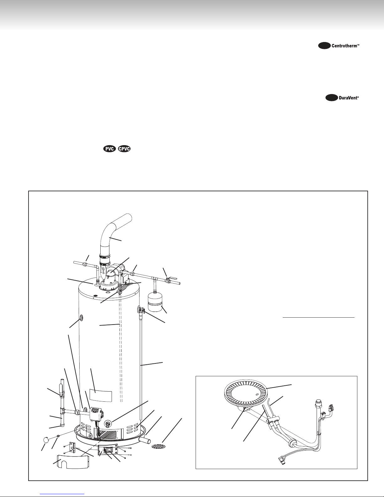
Figure 10
1) Vent pipe
2) Power vent assembly
3) Union
4) Cold water
manual shut-off valve
5) Cold water inlet
6) Expansion tank
7) Temperature
and pressure-relief valve
8) Overflow tube
9) Drain valve
10) Combustion
air intake holes
11) Drain pan
12) Free-flowing floor drain
13) Sight glass
14) Resettable Thermal Switch
15) Outer access door
28
27
29
26
25
Minimum Slope
1/4”/foot (21mm/m)
1
2
3
5
4
6
7
CENTROTHERM™ POLYPROPYLENE PIPE
®
(InnoFlue® single-wall vent system):
InnoFlue
Make sure that all horizontal runs have a minimum rise
of 5/8 inch per foot (56 mm/m) of run (see Figure 8).
Follow the vent pipe manufacturer’s instructions for the
appropriate venting support.
DURAVENT® POLYPROPYLENE PIPE
®
(PolyPro® single-wall gas vent system):
PolyPro
Make sure that all horizontal runs have a minimum rise
of 1/4 inch per foot (21 mm/m) of run (see Figure 8).
Follow the vent pipe manufacturer’s instructions for the
appropriate venting support.
16) Inner access door
17) Protective cover
18) Flammable vapour sensor
19) Cap
20) Drip leg (Sediment trap)
21) Gas supply
manual shut-off valve
22) Union
23) Gas control
24) Rating plate
25) Dip-tube
26) 12’ Power cord (3.86 m)
27) Side tappings
28) Hot water outlet
29) Union
30) Flame sensor
31) Ignitor
32) Burner orifice
33) Burner
22
21
20
19
18
17
16
23
24
15
14
13
8
33
9
10
11
12
32
30
31
98
INSTALLATION INSTRUCTIONS
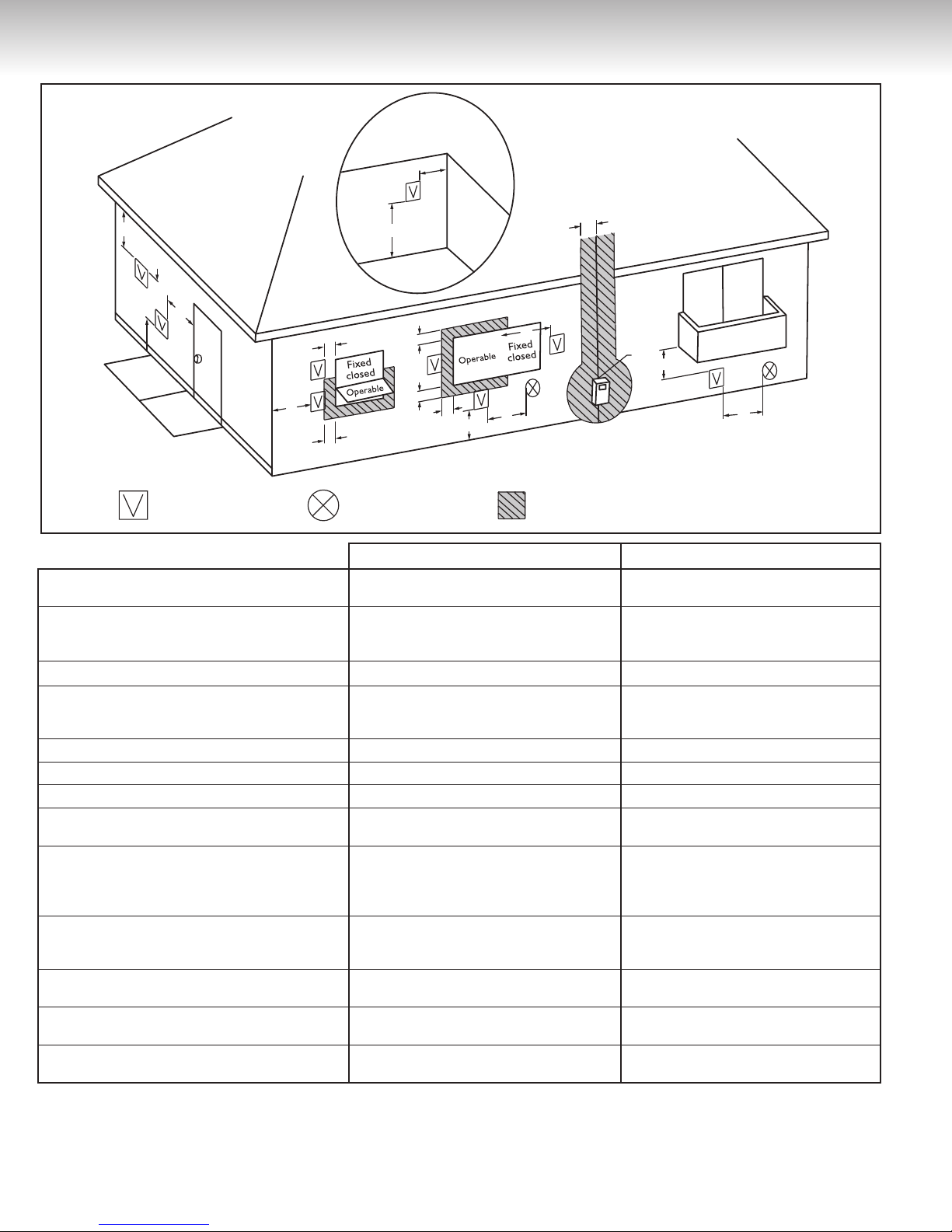
Figure 11
Inside
corner detail
G
D
E
B
= Vent terminal
C
F
B
= Air supply inlet
A
B
B
B
A
B
J
= Aera where terminal is not permitted
The Vent Termination must have a: Installations (Canada)
Clearance above grade, veranda, porch, deck, or
A)
balcony.
Clearance to windows or doors that may be
B)
opened.
Clearance to permanently closed windows. * *
C)
Vertical clearance to ventilated soffit located
above the terminal within a horizontal distance of
D)
2 feet (61 cm) from the center line of the terminal.
Clearance to unventilated soffit. * *
E)
Clearance to outside corner. * *
F)
Clearance to inside corner. * *
G)
Clearance to each side of center line extended
H)
above meter/regulator assembly.
Clearance to regulator vent oulet.
I)
Clearance to non-mechanical air supply inlet to
building or the combustion air inlet to any other
J)
appliance.
Clearance to a mechanical air supply inlet. 6 feet (1.83 m)
K)
Clearance above paved sidewalk or paved
L)
driveway located on public property.
Clearance under veranda, porch, deck, or
M)
balcony.
Notes:
1)
In acco rd an c e wi th t he c ur r en t CSA B149.1, Natural Gas and Propane Installation Code.
2)
In acco rd an c e wi th t he c ur r en t A NS I Z 2 2 3.1 / NFPA 54, Nation al Fue l Ga s C od e.
*
Clearance in accordance with local installation codes and the requirements of the gas supplier.
†
A vent shall not terminate where it may cause hazardous frost or ice accumulation on adjacent property surfaces.
‡
Permitted only if veranda, porch, deck, or balcony is fully open on a minimum of two (2) sides beneath the floor.
12 inches (30 cm) for appliances > 10,000 Btuh
(3kW)and≤100,000Btuh(30kW),36inches
(91 cm) for appliances > 100,000 Btuh (30 kW).
3 feet (91 cm) from the regulator vent outlet and
3 feet (91 cm) horizontally from the vertical
center line of the regulator vent outlet to a
maximum vertical distance of 15 feet (4.5 m).
12 inches (30 cm) for appliances > 10,000 Btuh
(3kW)and≤100,000Btuh(30kW),36inches
(91 cm) for appliances > 100,000 Btuh (30 kW).
12 inches (30 cm) 12 inches (30 cm)
* *
* *
7 feet (2.13 m)
12 inches (30 cm)
†
‡
H
I
M
1
4 feet (1.2 m) below or to side of
opening; 1 foot (300 mm) above opening.
4 feet (1,2 m) below or to side of opening;
1 foot (300 mm) above opening.
3 feet (91 cm) above if within 10 feet (3 m)
K
Installations (U.S.)
*
horizontally.
7 feet (2.13 m)*
*
2
10
 Loading...