

Giant Factories water heater, RESIDENTIAL POWER DIRECT VENT GAS-FIRED WATER HEATER Owner's Manual
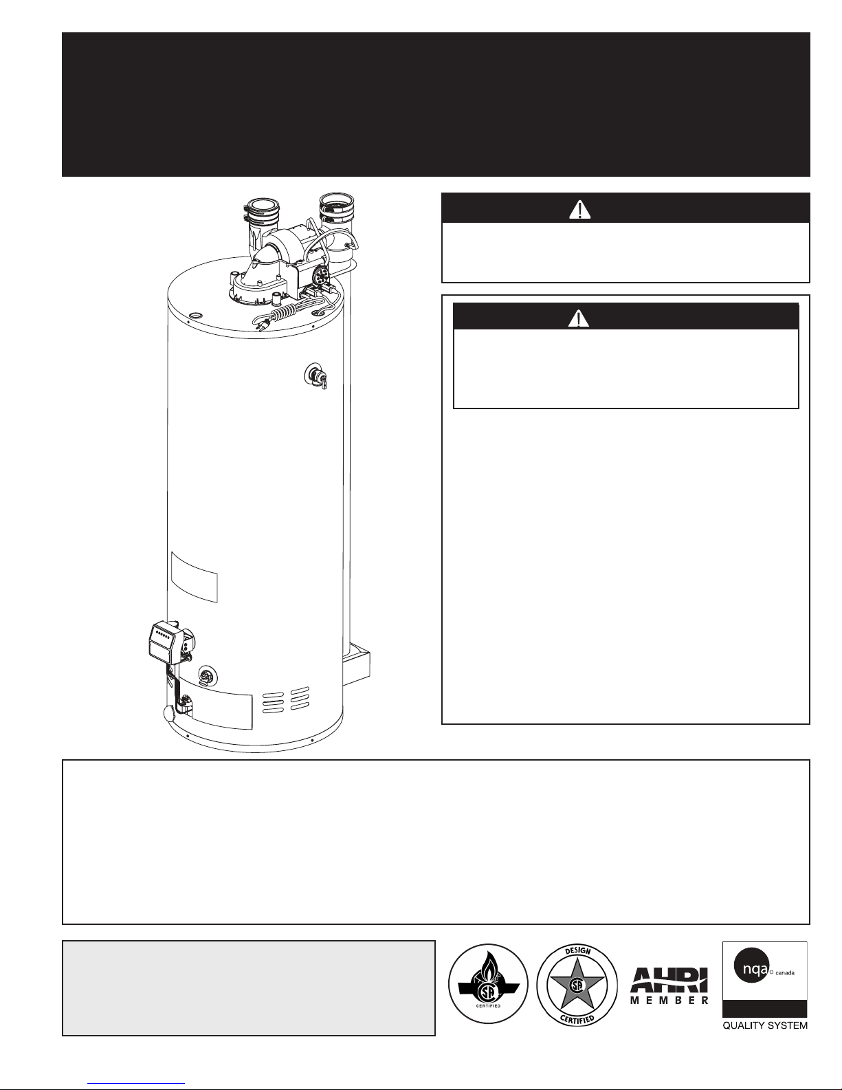
RESIDENTIAL POWER DIRECT VENT GAS-FIRED WATER HEATERS
WARNING
WARNING
ISO 9001
ENREGISTRÉ
ISO 9001
REGISTRED
(EQUIPPED WITH FVIR TECHNOLOGY)
OWNER’S MANUAL
INSTALLATION AND OPERATING INSTRUCTIONS
This water heater IS NOT design certified for
installation in a mobile home or for installation
outdoors.
If the information in these instructions is not
followed exactly, a fire or explosion may result
causing property damage, personal injury, or
death.
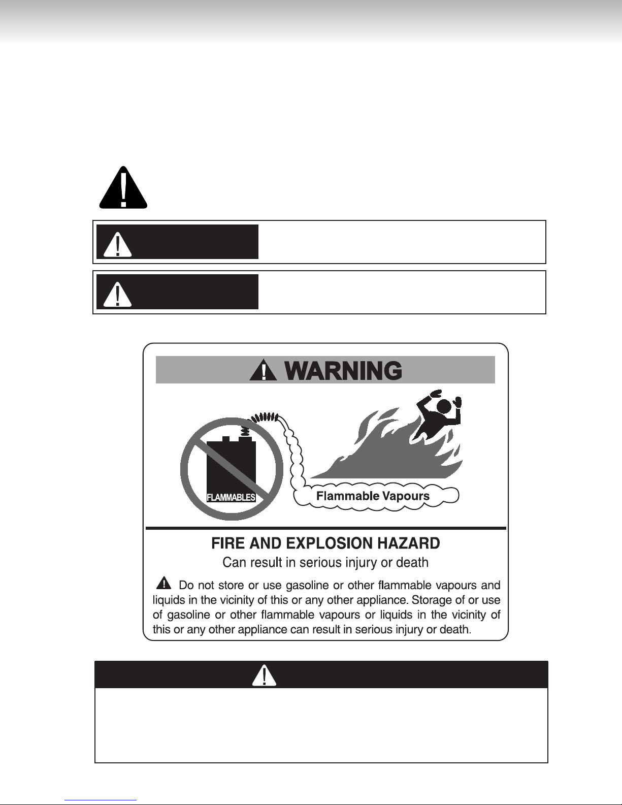
DO NOT store or use gasoline or other
flammable vapours and liquids in the vicinity of
this or any other appliance.
WHAT TO DO IF YOU SMELL GAS
•DO NOT try to light any appliance.
•DO NOT touch any electrical switch,
DO NOT use any phone in your building.
•From a neighbour’s phone, immediately
call your gas supplier. Follow the gas
supplier’s instructions.
•Ifyoucannotreachyourgassupplier,callthe
fire department.
Installation and service must be performed by
a qualified installer, service agency, or the gas
supplier.
IMPORTANT
READ THESE INSTRUCTIONS CAREFULLY BEFORE BEGINNING THE INSTALLATION. PROPER INSTALLATION
WILL PROVIDE SAFE & EFFICIENT SERVICE, AND AVOID NEEDLESS EXPENSES NOT COVERED BY THE
WARRANTY. READ THE PRODUCT WARRANTY IN THE OWNER’S MANUAL AND REMEMBER TO FILL
OUT AND RETURN TO THE MANUFACTURER ALL RELEVANT WARRANTY CARDS AND CERTIFICATES.
SHOULD YOU HAVE ANY QUESTIONS, PLEASE CONTACT YOUR LOCAL DEALER OR REFER TO THE
GETTING SERVICE FOR YOUR WATER HEATER SECTION OF THE OWNER’S MANUAL.
SAVE THIS INSTRUCTION MANUAL FOR FUTURE REFERENCES.
For your records, write the model and serial number here:
Model # ________________________________
Serial # _________________________________
54000018
© 2014 Giant Factories inc. Printed in Canada GI-IM004En-0114
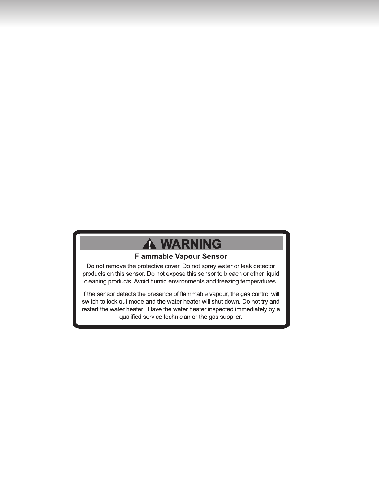
TABLE OF CONTENTS
Safety Information ......................... 3
Installation Instructions ................... 4
Location ................................ 4
Minimum Clearances .................... 4
Venting ................................. 4
Vent Pipe Preparation and Joining ........ 5
Through-the-Wall Venting Installation ..... 7
Concentric Vent Termination Kit Installation.. 7
Through-the-Roof Venting Installation ..... 8
Condensation in the Venting System ...... 8
Water Piping ............................ 8
Temperature & Pressure-Relief Valve ..... 9
Pressure Build-up in a Water System ..... 9
Filling the Water Heater .................. 9
Gas Connections ....................... 10
Wiring Diagram & Wiring ................. 10
Installation Instructions for Water Heaters
Approved for Combination Space
Heating and Potable Water Heating ...... 11
Installation Checklist .................... 12
Operating Instructions .................... 13
Lighting the Water Heater ............... 13
Lighting instructions .................... 13
Water Temperature Regulation .......... 14
Out of Fuel ............................. 15
General Maintenance ..................... 15
Housekeeping .......................... 15
Flammable Vapour Sensor .............. 15
Condensation .......................... 15
Burner Igniter Assembly ................. 16
Water Heater Tank ...................... 16
Temperature and Pressure-Relief Valve ... 16
Venting System Inspection ............... 16
Anode(s) ............................... 16
Draining the Water Heater ............... 16
Vacation ................................ 17
Getting Service for your Water Heater .... 17
Replacement Parts ........................ 18
Troubleshooting Guide .................... 19
Warranty.................................. 22
If flammable vapours are detected:
•
DO NOT try to light any appliance.
•
DO NOT touch any electrical switch, DO NOT use any phone in your building.
•From a neighbour’s phone, immediately call your gas supplier. Follow the gas supplier’s instructions.
•
If you cannot reach your gas supplier, call the fire department.
After the flammable vapours have been evacuated, contact a qualified service technician or the gas supplier to
have the water heater inspected immediately. Replacement of an FVIR technology equipped water
heater due to a flammable vapour shutdown is not covered under the terms of the Standard
Basic Limited Warranty.
2
SAFETY INFORMATION
WARNING
DANGER
WARNING
WARNING
Your safety and the safety of others is extremely important during the installation, operation, and servicing of this water heater. Many safety-related messages have been provided
in this manual and on your water heater. Always read and obey all safety messages. These
messages will point out the potential hazard, tell you how to reduce the risk of injury, and tell
you what will happen if the instructions are not followed.
This is the safety alert symbol. This symbol alerts you to potential hazards
that can kill or hurt you and others. All safety messages will follow the safety
alert symbol and either the word “DANGER” or “WARNING”.
Serious injury or death can occur if you do not follow the instructions immediately.
Serious injury or death can occur if you do not follow the instructions.
DO NOT use this water heater if any part has been under water. Immediately call a
qualified service technician to inspect the water heater and to replace any part of the
control system and any gas control which has been under water. Failure to follow this
instruction can result in property damage, personal injury, or death.
3
INSTALLATION INSTRUCTIONS
WARNING
DANGER
IMPORTANT
These instructions have been written as a guide for the proper installation and operation of your water heater,
and the manufacturer of this water heater will not accept any liability where these instructions have not been
followed. However, for your safety and to avoid damage caused by improper installation, this water heater must
be installed by a Certified Licensed Professional, and meet all local codes or, in the absence of local codes, the
latest edition of CAN/CSA B149.1, Natural Gas and Propane Gas Installation Code, in Canada, and/or the latest
edition of the National Fuel Gas Code, ANSI Z223.1/NFPA 54, in the United States.
Before proceeding with the installation instructions:
1) Inspect the water heater and its component parts for possible damage. DO NOT install or attempt to
repair any damaged component parts. If you detect any damage, contact the dealer where the water
heater was purchased or the manufacturer listed on the warranty card.
2) Verify that the type of gas being supplied corresponds to that which is marked on the rating plate and
gas control valve of the water heater.
Location
This water heater should be located close enough to the
outside wall so that it is within the venting requirements
listed in these installation instructions and as close as
possible to the main use of hot water. This location
must not be subject to freezing temperatures. The
water heater should be positioned, so that there is
easy access to the burner, gas control valve, and
drain valve. It must be located close to a suitable
free-flowing floor drain. Where a floor drain is not
adjacent to the water heater, a suitable drain pan
must be installed under the water heater (see Figure
5). This drain pan should be at least four (4) inches
(10.2 cm) larger than the diameter of the water heater, and at least one (1) inch (2.5 cm) deep, providing
access to the drain valve. This pan must be piped to
a suitable drain to prevent damage to property in the
event of a water leak from the piping, the relief valve,
or the water heater.
Sooner or later, all water heaters leak. The
manufacturer, based on national building codes,
has given the necessary instructions to prevent
damage to the building. Under no circumstances
is the manufacturer to be held liable for any water
damage, in connection with this water heater.
This water heater is approved for installation on either
a combustible or non-combustible floor. However,
should this water heater be installed directly on carpeting, the carpeting must be protected by a wood or
metal panel beneath the water heater. This panel
must extend at least three (3) inches (7.6 cm) beyond
the width and depth of the water heater. Should the
water heater be installed in an alcove or closet, the
entire floor area must be covered by the panel.
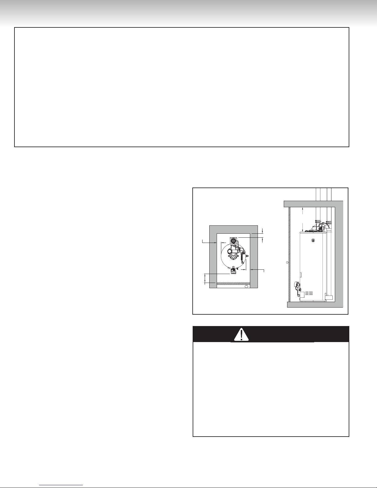
Minimum Clearances
The minimum clearances from combustible material
for this water heater are: Two (2) inches (5.1 cm)
from the sides and rear, four (4) inches (10.2 cm)
from the front, and eighteen (18) inches (45.7 cm)
from the top (see Figure 1).
Figure 1
18''
2'' min.
2'' min.
2'' min.
4'' min.
Venting
When installing the venting system, make sure to
follow all local codes or, in the absence of local
codes, the latest edition of CAN/CSA B149.1,
Natural Gas and Propane Gas Installation Code,
in Canada, and/or the latest edition of the National
Fuel Gas Code, ANSI Z223.1/NFPA54, in the
United States. Never operate the water heater
unless it is properly ventilated to the outdoors
and has adequate air supply for proper operation.
Failure to properly install the venting system could
result in property damage, personal injury, or death.
This water heater is a power direct vent gas water
heater that draws all of its combustion air from outside of the building and vents all of its combustion
gases directly outside of the building. Before install-
min.
4
INSTALLATION INSTRUCTIONS
WARNING
DANGER
Table 1
MAXIMUM EQUIVALENT LENGTH FOR VENT AND AIR INTAKE PIPES — DO NOT EXCEED MAXIMUM LENGTH OF PIPE
VENT AND AIR INTAKE PIPE DIAMETER 3 inch
Maximum length plus one 90o termination elbow 60.0 feet (15.2 m)
Minimum length plus one 90o elbow and plus one 90o termination elbow 2.5 feet (0.8 m)
One 45o radius elbow is equivalent, in straight pipe, to 4.0 feet (1.2 m)
One 90o radius elbow is equivalent, in straight pipe, to 7.0 feet (2.1 m)
Concentric Vent Termination (optional) 40.0 feet (12.2 m)
ing the vent piping, make sure that the vent system
layout has been properly planned. Make sure that
the flue baffle has been installed in the flue tube.
If the baffle is not present, immediately contact
the dealer where the water heater was purchased.
NEVER operate the water heater without the flue
baffle installed. Verify that the location of the water
heater respects all clearances from combustible
material, all venting requirements (see Table 1),
and that the vent terminations will be installed as
specified by all local codes or, in the absence of local
codes, the latest edition of CAN/CSA B149.1, Natural
Gas and Propane Installation Code, in Canada, and/
or the latest edition of the National Fuel Gas Code,
ANSI Z223.1/NFPA 54, in the United States (see
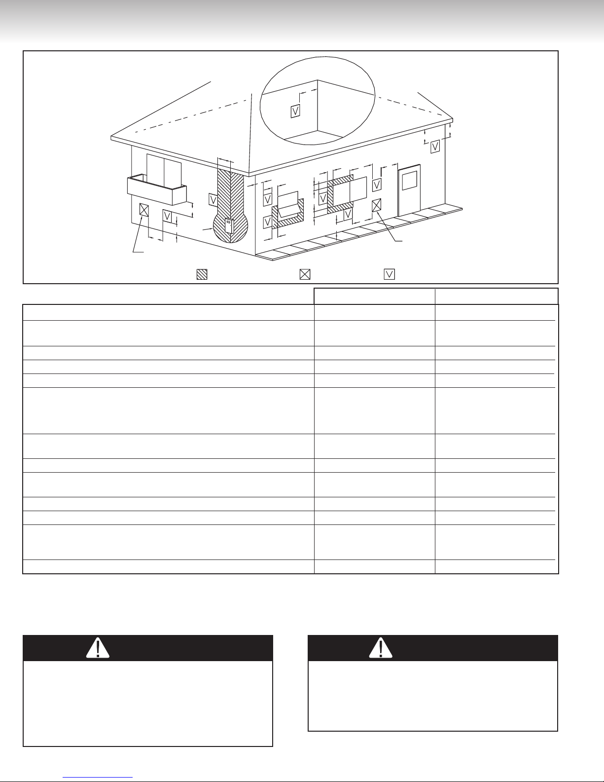
Figure 2).
This water heater must be vented directly to the
outdoors, either horizontally through the wall or
vertically through the roof. The venting must not be
attached to an existing chimney, or in common with
any other appliance, and must not be insulated. If
possible, locate the water heater so that the venting
length and number of elbows are kept to the minimum necessary to reach the outside.
Only three (3) inch (7.6 cm) schedule 40 PVC or
CPVC pipe and fittings may be used to vent this
water heater. A 90˚ elbow (supplied in the box)
must also be installed at the end of the air intake
piping to serve as the termination. The piping
and all the fittings must be permanently joined
using the appropriate primer and solvent-based
cement. Horizontal runs of vent pipe must be supported every three (3) feet (91 cm) and vertical runs
of vent pipe must be supported every five (5) feet
(1.5 m).
Plastic vent systems installed in Canada must be
certified to the STANDARD FOR TYPE BH GAS
VENTING SYSTEMS, ULC S636. Components
of the certified vent system must not be interchanged with other vent systems or unlisted
pipe/fittings. Plastic components and specified
primers and glues of the certified vent system
must be from a single vent system manufacturer and not intermixed with other vent system
manufacturer’s vent system parts unless those
are certified to be used with this system. Plastic
vent systems shall also be installed such that the
first three (3) feet (91 cm) of pipe from the water
heater outlet is readily accessible for visual
inspection. The air intake system does not have
to meet the requirement of ULC S636, so regular
schedule 40 PVC or CPVC pipes and fittings can
be used to convey the flow of fresh air to the
water heater.
Vent Pipe Preparation and Joining
ALWAYS read and obey all safety messages printed on the primer, cleaner, and cement containers.
Primer, cleaner, and cements are extremely flammable.
DO NOT
flames. They are harmful or fatal if swallowed. Their
vapours are also harmful. They may irritate eyes
and can be absorbed through the skin. Failure to follow these instructions can result in property damage,
personal injury, or death.
Primers, cleaners, solvents, and cements are available for PVC and CPVC pipe/fittings. When cementing the pipe/fittings, make sure to use only materials
approved for the type of pipe/fittings to be installed
and in all cases, follow the vent pipe/fittings manufacturers joining instructions. Never use all-purpose
cements, commercial glues and adhesives to join
PVC or CPVC pipe/fittings.
1) Cut pipe ends squarely, removing all burrs and dirt.
2) Dry fit the pipe/fitting to be connected to make
sure they fit properly.
3) Clean the pipe/fitting with the proper primer or
cleaner.
4) Apply a thin coat of cement to the fitting, avoiding
puddling inside.
5) Apply a liberal coat of cement to the pipe, leaving
no voids.
6) QUICKLY assemble parts while cement is fluid!
If you wait too long, re-coat pipe/fitting.
7) Push pipe completely into socket of fitting, turning as it goes until it bottoms out.
8) Hold pipe and fitting together for 30 seconds.
Then carefully clean off any excess material with
store these products near heat, sparks, or
5
INSTALLATION INSTRUCTIONS
WARNING
WARNING
Figure 2
H
MECHANICAL
AIR SUPPLY
F
J
A
E
AREA WHERE TERMINAL
IS NOT PERMITTED
C
INSIDE CORNER
DETAIL
K
FIXED
CLOSED
OPERABLE
B
D
B
B
AIR SUPPLY
INLET
B
OPERABLE
I
FIXED
CLOSED
M
L
B
B
G
NONMECHANICAL
AIR SUPPLY
VENT
TERMINAL
The Vent Termination must have a: Canadian Installations US Installations
A) Clearance above grade, veranda, porch, deck, or balcony. 12 inches (30 cm) 12 inches (30 cm)
B) Clearance to window or door that may be opened. 9 inches (23 cm) or
12 inches (30 cm) * * *
C) Clearance to outside corner.
D) Clearance to inside corner.
E) Clearance to service regulator vent outlet. 3 feet (91 cm) 3 feet (91 cm)
F ) Clearance to each side of center line extended above 3 feet (91 cm) within a 3 feet (91 cm) within a
meter/regulator assembly. height 15 feet (4.57 m) height 15 feet (4.57 m)
above the meter/regulator above the meter/regulator
assembly assembly
G ) Clearance to non-mechanical air supply inlet to building or
the combustion air inlet to any other appliance.
H) Clearance to a mechanical air supply inlet. 6 feet (1.82 m)
I ) Clearance above paved sidewalk or paved driveway
located on public property.
J) Clearance under veranda, porch, deck, or balcony. 12 inches (30 cm)** 12 inches (30 cm)**
K) Clearance to permanently closed window.
L) Vertical clearance to ventilated soffit located above the
terminal within a horizontal distance of 2 feet (61 cm) * *
from the centerline of the terminal.
M) Clearance to unventilated soffit.
Clearance in accordance with local installation codes and the requirements of the gas supplier.
*
For Canadian and US installations, the vent shall not terminate above a paved driveway that is located between two single family dwellings and serves both dwellings.
** The veranda, porch, or deck is fully open on a minimum of two sides beneath the floor.
*** 9 inches (23 cm) for appliances with 10,000 Btu/h to 50,000 Btu/h inputs and 12 inches (30 cm) for appliances greater than 50,000 Btu/h.
**** The vent terminal must terminate at least three (3) feet (91cm) above any forced air inlet duct located within ten (10) feet (3.05m).
12 inches (30 cm)
*
3 feet (91 cm)
*
12 inches (30 cm)
12 inches (30 cm) * * *
9 inches (23 cm) or
*
* * * *
7 feet (2.13 m) 7 feet (2.13 m)
* *
* *
In freezing weather, check for snow accumulation
around the water heater vent and air intake terminals
where they pass through the outside wall. The open
ends of the terminals must be installed at least 12
inches (30 cm) above the highest anticipated snowfall to prevent blockage by snow.
Check that all openings and gaps in the outside
wall near and around where the vent and air
intake pipes pass through the exterior wall are
sealed to prevent infiltration of combustion
products into the building.
6

INSTALLATION INSTRUCTIONS
WARNING
Terminaison
d’entrée d’air
Terminaison
du tuyau
d’échappement
8”
: La terminaison du tuyau d’échappement ne doit pas être
installée en-dessous
de la terminaison
d’entrée d’air ni
à moins de 8”
(20.3 cm) de
celle-ci.
2"
18'' min.
3'' min. / 8'' max.
18'' min.
8'' min.
Dans toutes directions
8'' min.
Dans toutes directions
Terminaison
d’entrée d’air 90°
18'' min.
Terminaison
de l’entée d’air 90°
18'' min.
Terminaison d’évent en «T»
a cloth. Allow connections a sufficient time to
cure before disturbing.
9) Remember that vent pipes must be adequately
and securely suppported.
Through-the-Wall Venting Installation
IMPORT
When installing the vent piping make sure that the
vent terminal is NEVER installed below the air intake
terminal. The air intake terminal must always face
downward. Failure to follow this instruction could
result in property damage, personal injury, or death.
Two vent terminal options are available to vent this
water heater. The first is a standard 90˚ elbow facing
downward (see Figure 4a) and the second is the concentric vent termination kit (see Figure 4b).
The air intake screen can be removed on the air
intake terminal in cold environment. Thus, this may
make the air intake susceptible to debris build-up in
the air intake pipe. A second screen is installed in
the rubber adaptor on the air inlet Tee at the back
of the water heater to prevent debris from entering
the water heater. This screen can be accessed for
cleaning by removing the pipe on top of the rubber
adaptor. If the air intake screen is removed to prevent
freezing, it is strongly recommended that the air inlet
screen be installed during the spring. Cut or drill two
(2) holes through the exterior wall, slightly larger than
the diameter of the vent pipe. The larger holes will
allow for final alignment with the water heater. Extend
a section of pipe through each hole to the outside
and attach the terminal assembly to the exterior end
of each pipe. The vent and air intake terminals must
be at least eight (8) inches (20.3 cm) apart and the
vent terminal must NEVER be installed below the
Figure 3
18'' min.
18'' min.
8'' min.
IN ANY DIRECTION
90° INTAKE TERMINAL
3'' min. / 8'' max.
18'' min.
18'' min.
TEE VENT
TERMINAL
8'' min.
IN ANY
DIRECTION
90° INTAKE
TERMINAL
2"
air intake terminal for any reason (see Figure 4a).
The air intake terminal and the vent terminal must
terminate on the same exterior wall (same atmospheric
pressure zone).
IMPORTANT
The air intake equivalent vent length must be equal
to or less than the exhaust equivalent vent length.
Figure 4a
: Vent Terminal shall never be installed below air
intake terminal
and within 8”
of air intake
terminal.
8"
Air Intake
Terminal
Figure 4b
Exhaust
Air intake
Clamp or Strap
(field supplied)
Exterior wall
1" (2,5 cm) Min.
2" (5 cm) Max.
Exhaust
Air
intake
* see local codes
Connect and secure all piping and elbows from the
power venter to the wall. Make sure that all horizontal runs have a minimum rise of 1/4 inch per foot (21
mm/m) of run (see Figure 5). When the installation is
completed, the vent and air intake terminals must be at
two (2) inches (5.1 cm) from the exterior surface of the
wall (see Figure 4b). Do not extend vent or air intake
piping past this length. Make sure that all piping is
properly supported. If the venting will pass through an
enclosed area, make sure to leave at least one (1) inch
(2.5 cm) clearance around the piping for air circulation.
Concentric Vent Termination Kit Installation
A three (3) inch Concentric Vent Termination Kit (IPEX
model 196006) may be used for side wall termination
installations (Do not use this kit for Through-the-roof
installation). Using this Concentric Vent Termination
Kit will reduce the maximum allowable equivalent vent
pipe lenght from sixty (60) feet (18.3 m) to forty (40)
feet (12.2 m) for both air intake and exhaust systems.
Figure 4b illustrates the Concentric Vent Termination
Kit for side wall installation. See manufacturer’s
instructions for complete installation details.
Vent
Terminal
Optional
Elbow*
Distance above
average snowfall or grade,
reference: CSA B149.1
7
 Loading...