

Giant Factories RESIDENTIAL DIRECT VENT GAS-FIRED WATER HEATERS Owner's Manual
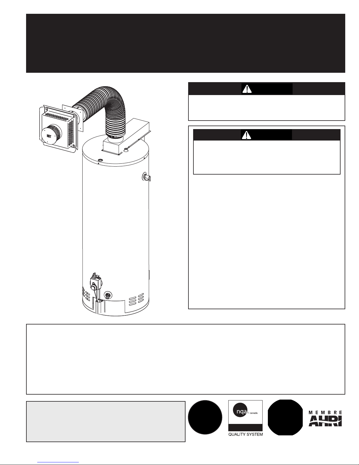
RESIDENTIAL DIRECT VENT GAS-FIRED WATER HEATERS OWNER’S MANUAL
WARNIN G
WARNIN G
ISO 9001
REGISTRED
(MEET THE FVIR TECHNOLOGY STANDARDS)
INSTALLATION AND OPERATING INSTRUCTIONS
This water heater IS NOT design certified for
installation in a manufactured (mobile) home or
for installation outdoors.
If the information in these instructions is not
followed exactly, a fire or explosion may
result causing property damage, personal
injury, or death.
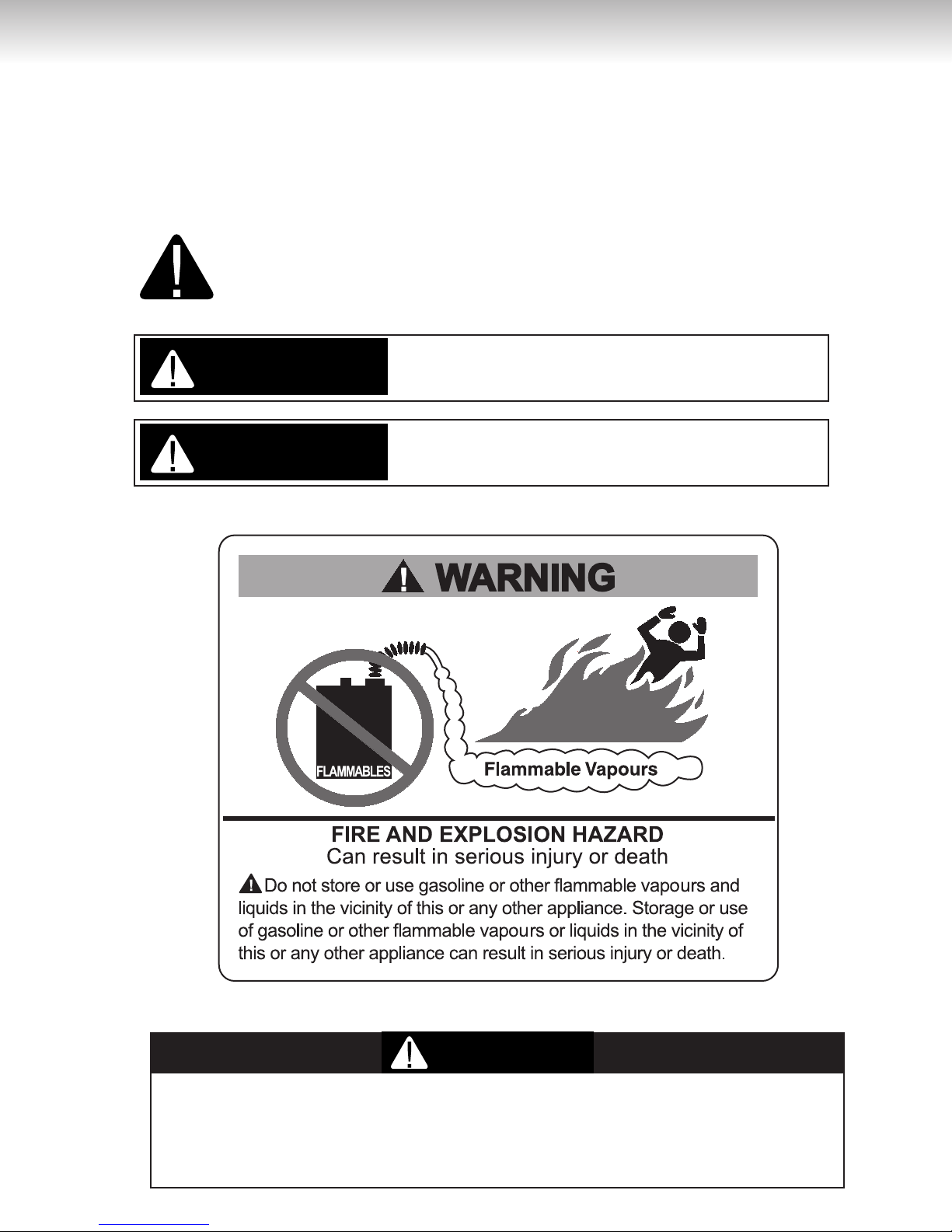
DO NOT store or use gasoline or other
flammable vapours and liquids in the vicinity of
this or any other appliance.
WHAT TO DO IF YOU SMELL GAS
• DO NOT try to light any appliance.
• DO NOT touch any electrical switch,
DO NOT use any phone in your building.
• From a neighbour’s phone, immediately
call your gas supplier. Follow the gas
supplier’s instructions.
• If you cannot reach your gas supplier, call the
fire department.
Installation and service must be performed by
a qualified installer, service agency, or the gas
supplier.
IMPORTANT
READ THESE INSTRUCTIONS CAREFULLY BEFORE BEGINNING THE INSTALLATION. PROPER
INSTALLATION WILL PROVIDE SAFE AND EFFICIENT SERVICE, AND AVOID NEEDLESS EXPENSE NOT
COVERED BY THE WARRANTY. READ THE PRODUCT WARRANTY CONTAINED IN THIS MANUAL AND
REMEMBER TO FILL OUT AND RETURN TO THE MANUFACTURER ALL RELEVANT WARRANTY CARDS
AND CERTIFICATES. SHOULD YOU HAVE ANY QUESTIONS, PLEASE CONTACT YOUR LOCAL DEALER OR
REFER TO THE GETTING SERVICE FOR YOUR WATER HEATER SECTION OF THIS MANUAL.
SAVE THIS MANUAL FOR FUTURE REFERENCES.
For your records, write the model and serial number here:
Model # ____________________________
Serial # ____________________________
54000013
© 2014 Giant Factories Inc. Printed in Canada
GI-IM018En-0114

TA BL E OF C O NT EN TS
Safety Information . . . . . . . . . . . . . . . . . . . . . . . . . . . . . . . . . . . . . . . . . . . . . . . . . . . . . . . . . . . . . . . . . . . . . . .2
Installation Instructions . . . . . . . . . . . . . . . . . . . . . . . . . . . . . . . . . . . . . . . . . . . . . . . . . . . . . . . . . . . . . . . . . .3
Location . . . . . . . . . . . . . . . . . . . . . . . . . . . . . . . . . . . . . . . . . . . . . . . . . . . . . . . . . . . . . . . . . . . . . . . . . . . . . .4
Minimum Clearances . . . . . . . . . . . . . . . . . . . . . . . . . . . . . . . . . . . . . . . . . . . . . . . . . . . . . . . . . . . . . . . . . . . .4
Venting . . . . . . . . . . . . . . . . . . . . . . . . . . . . . . . . . . . . . . . . . . . . . . . . . . . . . . . . . . . . . . . . . . . . . . . . . . . . . . .4
Co-axial Flexible Vent Pipe Kit (Vent Kit) . . . . . . . . . . . . . . . . . . . . . . . . . . . . . . . . . . . . . . . . . . . . . . . . . . . . .5
Vent kit installation . . . . . . . . . . . . . . . . . . . . . . . . . . . . . . . . . . . . . . . . . . . . . . . . . . . . . . . . . . . . . . . . . . . . . .5
Water Piping . . . . . . . . . . . . . . . . . . . . . . . . . . . . . . . . . . . . . . . . . . . . . . . . . . . . . . . . . . . . . . . . . . . . . . . . . . .9
Temperature & Pressure-Relief Valve . . . . . . . . . . . . . . . . . . . . . . . . . . . . . . . . . . . . . . . . . . . . . . . . . . . . . . . .9
Pressure Build-up in a Water System . . . . . . . . . . . . . . . . . . . . . . . . . . . . . . . . . . . . . . . . . . . . . . . . . . . . . . . .9
Filling the Water Heater . . . . . . . . . . . . . . . . . . . . . . . . . . . . . . . . . . . . . . . . . . . . . . . . . . . . . . . . . . . . . . . . .10
Gas Connections . . . . . . . . . . . . . . . . . . . . . . . . . . . . . . . . . . . . . . . . . . . . . . . . . . . . . . . . . . . . . . . . . . . . . . .11
Installation Instructions for Water Heaters Approved for
Space Heating and Potable Water Heating . . . . . . . . . . . . . . . . . . . . . . . . . . . . . . . . . . . . . . . . . . . . . . . .11
Installation Checklist . . . . . . . . . . . . . . . . . . . . . . . . . . . . . . . . . . . . . . . . . . . . . . . . . . . . . . . . . . . . . . . . . . . .14
Operating Instructions . . . . . . . . . . . . . . . . . . . . . . . . . . . . . . . . . . . . . . . . . . . . . . . . . . . . . . . . . . . . . . . . . .14
Lighting the Water Heater . . . . . . . . . . . . . . . . . . . . . . . . . . . . . . . . . . . . . . . . . . . . . . . . . . . . . . . . . . . . . . . .14
Water Temperature Regulation . . . . . . . . . . . . . . . . . . . . . . . . . . . . . . . . . . . . . . . . . . . . . . . . . . . . . . . . . . . .15
Out of Fuel . . . . . . . . . . . . . . . . . . . . . . . . . . . . . . . . . . . . . . . . . . . . . . . . . . . . . . . . . . . . . . . . . . . . . . . . . . .15
General Maintenance . . . . . . . . . . . . . . . . . . . . . . . . . . . . . . . . . . . . . . . . . . . . . . . . . . . . . . . . . . . . . . . . . . .16
Housekeeping . . . . . . . . . . . . . . . . . . . . . . . . . . . . . . . . . . . . . . . . . . . . . . . . . . . . . . . . . . . . . . . . . . . . . . . . .16
Condensation . . . . . . . . . . . . . . . . . . . . . . . . . . . . . . . . . . . . . . . . . . . . . . . . . . . . . . . . . . . . . . . . . . . . . . . . .16
Main Burner & Pilot . . . . . . . . . . . . . . . . . . . . . . . . . . . . . . . . . . . . . . . . . . . . . . . . . . . . . . . . . . . . . . . . . . . . .16
Water Heater Tank . . . . . . . . . . . . . . . . . . . . . . . . . . . . . . . . . . . . . . . . . . . . . . . . . . . . . . . . . . . . . . . . . . . . .16
Temperature and Pressure-Relief Valve . . . . . . . . . . . . . . . . . . . . . . . . . . . . . . . . . . . . . . . . . . . . . . . . . . . . .16
Venting System Inspection . . . . . . . . . . . . . . . . . . . . . . . . . . . . . . . . . . . . . . . . . . . . . . . . . . . . . . . . . . . . . . .16
Anode . . . . . . . . . . . . . . . . . . . . . . . . . . . . . . . . . . . . . . . . . . . . . . . . . . . . . . . . . . . . . . . . . . . . . . . . . . . . . . .16
Draining the Water Heater . . . . . . . . . . . . . . . . . . . . . . . . . . . . . . . . . . . . . . . . . . . . . . . . . . . . . . . . . . . . . . .17
Vacation . . . . . . . . . . . . . . . . . . . . . . . . . . . . . . . . . . . . . . . . . . . . . . . . . . . . . . . . . . . . . . . . . . . . . . . . . . . . . .17
Getting Service for your Water Heater . . . . . . . . . . . . . . . . . . . . . . . . . . . . . . . . . . . . . . . . . . . . . . . . . . . . . .17
Replacement Parts . . . . . . . . . . . . . . . . . . . . . . . . . . . . . . . . . . . . . . . . . . . . . . . . . . . . . . . . . . . . . . . . . . . . .18
Troubleshooting Guide . . . . . . . . . . . . . . . . . . . . . . . . . . . . . . . . . . . . . . . . . . . . . . . . . . . . . . . . . . . . . . . . . .19
Warranty . . . . . . . . . . . . . . . . . . . . . . . . . . . . . . . . . . . . . . . . . . . . . . . . . . . . . . . . . . . . . . . . . . . . . . . . . . . . . .22
This water heater meets the FVIR requirements in the standard for water heater.
It is equiped with a sealed combustion chamber and air intake system so it will not use any surounding air
for combustion; it will use combustion air from outside the building where the vent terminal is located. thus it will
prevent combustuble vapours from igniting outsite the water heater in the event that gasoline or other
flammable vapours and liquids are improperly stored in the area where the water heater is located.
If flammable vapours are detected:
• DO NOT try to light any appliance.
• DO NOT touch any electrical switch, DO NOT use any phone in your building.
• From a neighbour’s phone, immediately call your gas supplier.
Follow the gas supplier’s instructions.
• If you cannot reach your gas supplier, call the fire department.
After the flammable vapours have been evacuated, contact a qualified service technician or the manufacturer for
further instructions.
2
SA FE TY INF O RM AT IO N
WARNING
DANGER
WARNING
Your safety and the safety of others is extremely important during the installation, operation,
and servicing of this water heater. Many safety related messages have been provided in this
manual and on your water heater. Always read and obey all safety messages. These messages
will point out the potential hazard, tell you how to reduce the risk of injury, and tell you what
will happen if the instructions are not followed.
This is the safety alert symbol. This symbol alerts you to potential hazards
that can kill or hurt you and others. All safety messages will follow the safety
alert symbol and either the word “DANGER” or “WARNING”.
Serious injury or death can occur if you do not follow
the instructions immediately.
Serious injury or death can occur if you do not follow
the instructions.
DO NOT use this water heater if any part has been under water. Immediately call a
qualified service technician to inspect the water heater and to replace any part of the
control system and any gas control which has been under water. Failure to follow this
instruction can result in property damage, personal injury, or death.
3
IN STALL AT I ON I N ST RU CT I O N S
DANGER
IMPORTANT
These instructions have been written as a guide for the proper installation and operation of your water heater, and
the manufacturer of this water heater will not accept any liability where these instructions have not been followed.
However, for your safety and to avoid damage caused by improper installation, this water heater must be installed
by a Certified Licensed Professional, and meet all local codes or, in the absence of local codes, CAN/CSA B149.1,
Natural Gas and Propane Gas Installation Code, in Canada, and/or the National Fuel Gas Code, ANSI
Z223.1/NFPA 54, in the United States.
Before proceeding with the installation instructions:
1) Inspect the water heater and its component parts for possible damage. DO NOT install or attempt to
repair any damaged component parts. If you detect any damage, contact the dealer where the water
heater was purchased or the manufacturer listed on the warranty card.
2) Verify that the type of gas being supplied corresponds to that which is marked on the rating plate and gas
control valve of the water heater.
Location
This water heater should be located close enough to the
outside wall so that it is within the venting requirements
listed in these installation instructions and as close as
possible to the main use of hot water. This location must
not be subject to freezing temperatures. The water
heater should be positioned, so that there is easy
access to the burner, gas control valve, and drain valve.
It must be located close to a suitable free-flowing floor
drain. Where a floor drain is not adjacent to the water
heater, a suitable drain pan must be installed under the
water heater (see Figure 9). This drain pan should
be at least four (4) inches (10.2 cm) larger than the
diameter of the water heater, and at least one (1) inch
(2.5 cm) deep, providing access to the drain valve. This
pan must be piped to a suitable drain to prevent
damage to property in the event of a water leak from the
piping, the relief valve, or the water heater.
Sooner or later, all water heaters leak. The
manufacturer, based on national building codes,
has given the necessary instructions to prevent
damage to the building. Under no circumstances
is the manufacturer to be held liable for any water
damage, in connection with this water heater.
This water heater is approved for installation on either
a combustible or non-combustible floor. However,
should this water heater be installed directly on
carpeting, the carpeting must be protected by a wood
or metal panel beneath the water heater. This panel
must extend at least three (3) inches (7.6 cm) beyond
the width and depth of the water heater. Should the
water heater be installed in an alcove or closet, the
entire floor area must be covered by the panel.
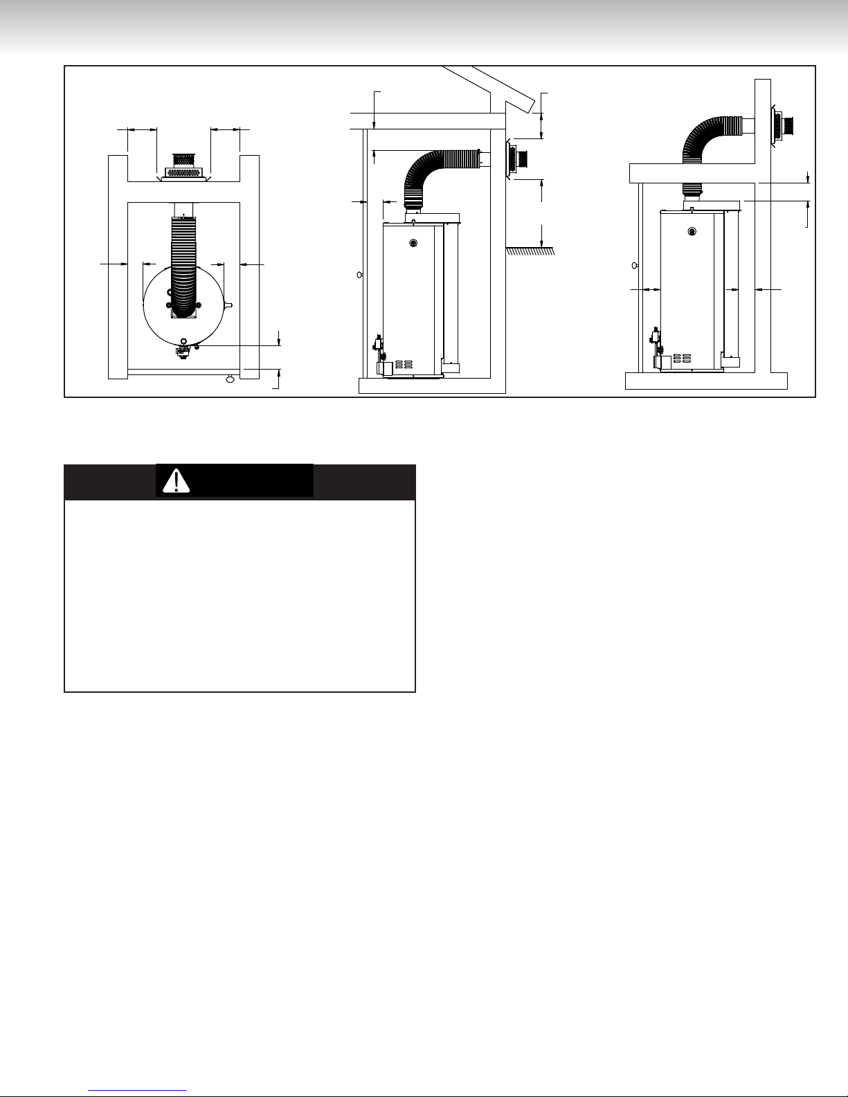
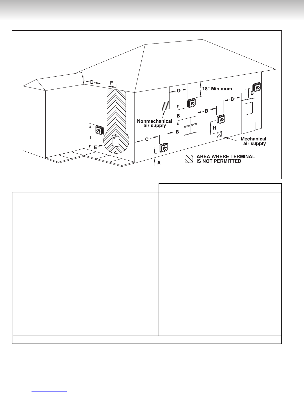
Minimum Clearances
The minimum clearances from combustible material
for this water heater are: Two (2) inches (5.1 cm)
from the sides, zero (0) inches from the rear, four (4)
inches (10.2 cm) from the front, one (1) inch from the
vent piping, and two (2) inches (5,1 cm) from the
direct vent-air intake terminal box (see Figure 1).
Venting
When installing the venting system, make sure to
follow all local codes or, in the absence of local
codes, CAN/CSA B149.1, Natural Gas and Propane
Gas Installation Code, in Canada, and/or the
National Fuel Gas Code, ANSI Z223.1/NFPA54, in
the United States. Never operate the water heater
unless it is properly ventilated to the outdoors and
has adequate air supply for proper operation. Failure
to properly install the venting system could result in
property damage, personal injury, or death.
This water heater is a direct vent gas water heater that
draws all of its combustion air from outside of the
building and vents all of its combustion gases directly
outside of the building. Before installing the vent piping,
make sure that the vent system layout has been
properly planned. Make sure that the flue baffle has
been installed in the flue tube. If the baffle is not
present, immediately contact the dealer where the
water heater was purchased. Never operate the water
heater without the flue baffle installed. Verify that the
location of the water heater respects all clearances
from combustible material, all venting requirements
(see Figure 1), and that the vent termination will be
installed as specified by all local codes or, in the
absence of local codes, CAN/CSA B149.1, Natural Gas
and Propane Installation Code, in Canada, and/or the
National Fuel Gas Code, ANSI Z223.1/NFPA 54, in the
United States (see Figure 2).
Note: Make sure to protect the building materials
4
Grade Line
2'' min.
2'' min.
18'' min.
18'' min.
1'' min. around
0'' min.
12'' min.
18'' min.
4'' min.
4'' min.
4'' min.
2'' min.
WARN ING
IN STALL AT I ON I N ST RU CT IO N S
Figure 1
from degradation by flue gases from the vent
termination.
Co-axial Flexible Vent Pipe Kit (Vent Kit)
DO NOT install this water heater if any of the parts
are damaged. The vent kit must be properly
installed. All horizontal runs of piping must have a
minimum rise of 1/4 inch per foot (21 mm/m) of run.
It is important to completely seal all the vent kit joints
where indicated in these instructions with high
temperature silicone sealant. A tube is supplied with
every direct vent water heater. Failure to properly
install the vent kit can result in property damage,
personal injury, or death.
This water heater has been shipped with a complete
vent kit. This kit includes:
• A three (3) inch (7.6 cm) inner, five (5) inch (12.7 cm)
outer co-axial “Wind-Tamer” vent termination.
• An outer wall mounting plate
• An inner wall back plate
• A length of three (3) inch (7.6 cm) inner, six (6) inch
(15.2 cm) outer co-axial flexible vent pipe with
reducer installed
• A six (6) inch (15.2 cm) to five (5) inch (12.7 cm)
reducer
• Two (2), three (3) inch (7.6 cm) hose clamps
• A six (6) inch (15.2 cm) hose clamp
• A tube of high temperature silicone
• Eight (8) wall anchors
• Eight (8) #10 x 1" screws
• Four (4) washers
• Six (6) 1/2" thread cutting screws
Vent Kit Installation
The following instructions detail the installation of the
co-axial flexible vent pipe kit supplied with every water
heater.
1) Place the water heater in it's final position (refer to
the Location and Minimum Clearances sections
for correct positioning requirements) and verify if
you are able to install the vent kit in accordance with
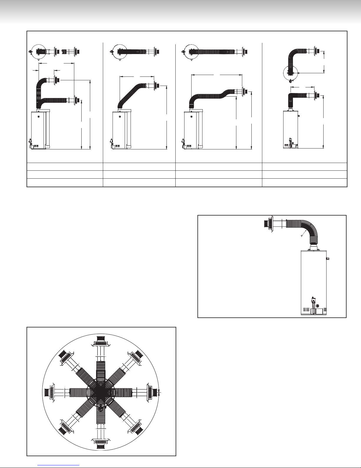
the specifications illustrated in Figure 3.
Note:
a) The vent kit of this water heater can be installed
in any 360˚ configuration as long as the proper
clearances for installation, plumbing, operation,
and servicing are maintained (see Figure 3a).
b)
The minimum inner radius for the vent pipe
curvature is 11" (27,9 cm) (use the water heater
outside radius as reference, see Figure 3b).
c) The maximum vent pipe curvature is 90˚
(see Figure 3c).
d) You can’t use both setup #3 and setup #4 on the
same vent pipe installation.
2) Locate where the vent termination is going to be
installed and cut a five and one half (5 1/2) inch
(14 cm) diameter clearance hole through the wall
(see Figure 4).
3) Outside of the building, position the outer wall
mounting plate and the termination kit over the
center of the wall opening. Mark the hole locations
for the mounting screws. Drill 1/4'' diameter holes in
the wall for the four (4) wall anchors. Install the wall
anchors and attach the outer wall mounting plate
5
IN STALL AT I ON I N ST RU CT I O N S
The Vent Termination must have a : Canadian Installations US Installations
A) Clearance above grade, veranda, porch, deck, or balcony1. 12 inches (30 cm) 12 inches (30 cm)
B) Clearance to window or door that may be opened. 12 inches (30 cm) 9 inches (23 cm)
C) Clearance to outside corner
**
D )mc 64( sehcni 81)mc 64( sehcni 81.renroc edisni ot ecnaraelC)
E) Clearance to any gas service regulator vent outlet. 3 feet (91 cm) 3 feet (0.91 m)
F) Clearance to each side of center line extended above 3 feet (91 cm) within a 3 feet (91 cm) within a
)m 75.4( teef 51 thgieh)m 75.4( teef 51 thgieh.ylbmessa rotaluger/retem
above the meter/regulator above the meter/regulator
assembly assembly
G) Clearance to non-mechanical air supply inlet to building or
the combustion air inlet to any other appliance.
H )m 28.1( teef 6.telni ylppus ria lacinahcem a ot ecnaraelC)
* *
I) Clearance above paved sidewalk or paved driveway
located on public property.
Vertical clearance to any unventilated soffit, overhang, or
other irregularity located above the terminal within a horizontal
distance of 18 inches (46 cm) from the center line of the terminal.
18 inches (46 cm) 18 inches (46 cm)
Vertical clearance to any ventilated soffit, overhang, or other
irregularity located above the terminal within a horizontal
distance of 18 inches (46 cm) from the center line of the terminal.
**
Clearance under veranda, porch, deck, or balcony. Shall not Shall not
Clearance to permanently closed window.*
12 inches (30 cm) 12 inches (30 cm)
7 feet (2.13 m) 7 feet (2.13 m)
Figure 2
1
Make sure to take into consideration the expected snow fall when determining this clearance.
Clearance in accordance with local installation codes and the requirements of the gas supplier.
*
** The vent terminal must terminate at least three (3) feet (91cm) above any forced air inlet duct located within ten (10) feet (3.05m).
For Canadian and US installations, the vent shall not terminate above a paved driveway that is located between two single family dwellings and serves both dwellings.
6
IN STALL AT I ON I N ST RU CT IO N S
Amax
Bmin
Bmax
Amin
B
A
C
B
A
A
B
D
360
11''
Figure 3
SETUP #1 SETUP #2 SETUP #3 SETUP #4
AB AB ABCABD
Max. 90'' Min. 76'' Max. 90'' Max. 98'' Max. 90'' Min. 76'' -- Max. 72'' Min. 76'' Max. 28''
Min. 26'' Max. 144'' Min. 26'' Min. 76'' Min. 26'' -- -- Min. 26'' Min. 76'' Max. 74''
and the termination kit with the four (4) #10 x 1''
screws and washers. Make sure that the rain guard
and the word “HOT” on the end of the vent-air intake
terminal are oriented properly. Caulk the junction of
the outer wall mounting plate and the exterior wall
with exterior type silicone sealant.(see Figure 4).
4) Inside the building, slide the back plate over the
5 inch (12.7 cm) pipe of the termination kit until it is
flush with the wall. Mark the hole locations for the
mounting screws. Drill 1/4'' diameter holes in the
wall for the four (4) wall anchors. Install the wall
anchors and secure the back plate with the four
(4)#10 x 1'' screws. (see Figure 5).
5) Apply the high temperature sealant (silicone or other
material suitable for 315˚F [600˚C] continuous
service) to the 3 inch (7.6 cm) pipe of the termina-
Figure 3a
tion kit and the two ends (5 inch (12.7 cm) & 6 inch
(15.2 cm)) of the free reducer. Insert the 6 inch
(15.2 cm) end of the reducer into the end of the
Figure 3b
flexible pipe that does not already have a reducer
installed, and secure them together with a six (6)
inch (15.2 cm) hose clamp. Pull the 3 inch (7.6 cm)
flexible pipe over the 3 inch (7.6 cm) pipe of the
termination kit. Secure them together with a three
(3) inch (7.6 cm) hose clamp. Insert the 5 inch
(12.7 cm) end of the free reducer into the 5 inch
(12.7 cm) pipe of the termination kit. Drill three (3)
holes, 120˚ apart, through the 5 inch (12.7 cm)
diameter termination kit pipe and reducer, and
secure them together with three (3) 1/2'' thread
cutting screws (see Figure 6).
6) At the other end of the flexible pipe, pull the three (3)
inch (7.6 cm) and the six (6) inch (15.2 cm) pipe
(with reducer already installed) towards the water
heater. Make sure to pull the six (6) inch (15.2 cm)
7
 Loading...