

Giant Factories OG32 Owner's Manual
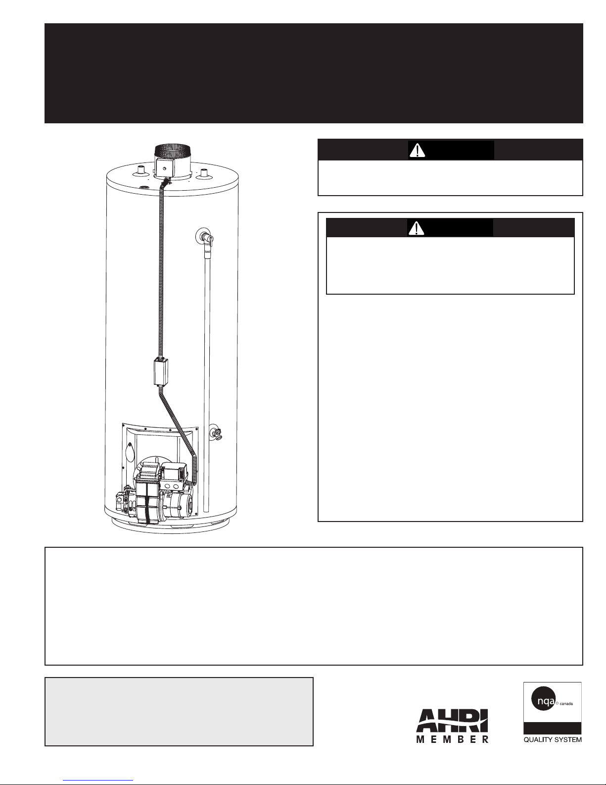
RESIDENTIAL OIL-FIRED WATER HEATERS
ISO 9001
ENREGISTRÉ
OWNER’S MANUAL
INSTALLATION AND OPERATING INSTRUCTIONS
WARNING
This water heater IS NOT design certified for
installation outdoors.
WARNING
If the information in these instructions is not
entirely followed, a fire or explosion may
result causing property damage, personal
injury or death.
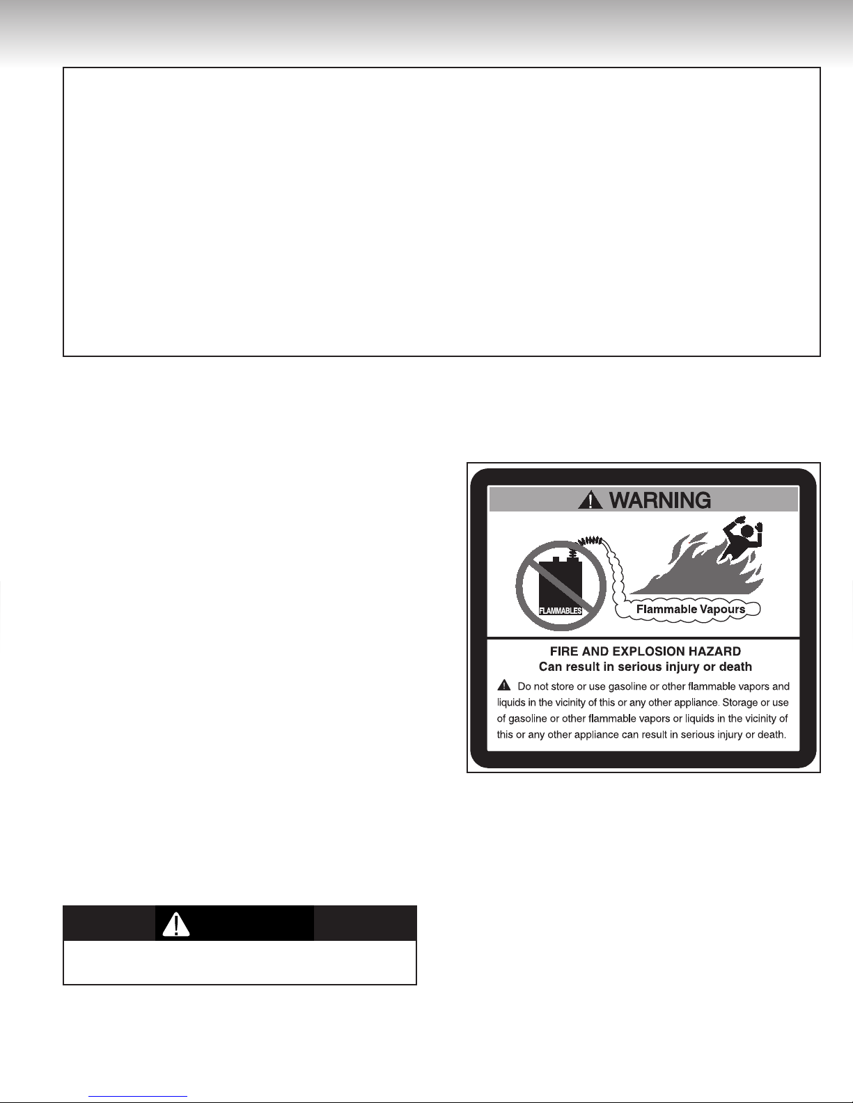
• DO NOT STORE, use gasoline or any
other flammable vapours or liquids in the
vicinity of this or any other appliance.
• DONOTUSE gasoline, crank case oil or oil
containing gasoline.
• DO NOT TAMPER with the unit or
controls.
• DONOTLEAVE paper or rags close to the
burner or the water heater.
READ THESE INSTRUCTIONS CAREFULLY BEFORE BEGINNING THE INSTALLATION. PROPER INSTALLATION
WILL PROVIDE SAFE AND EFFICIENT SERVICE AND AVOID NEEDLESS EXPENSE NOT COVERED BY THE
WARRANTY. READ THE PRODUCT WARRANTY CONTAINED IN THIS MANUAL AND REMEMBER TO FILL
OUT AND RETURN TO THE MANUFACTURER ALL RELEVANT WARRANTY CARDS AND CERTIFICATES.
SHOULD YOU HAVE ANY QUESTIONS, PLEASE CONTACT YOUR LOCAL DEALER OR REFER TO THE
GETTING SERVICE FOR YOUR WATER HEATER SECTION OF THIS MANUAL.
SAVE THIS MANUAL FOR FUTURE REFERENCES.
For your records, write the model and serial number here:
Model # ________________________________
Serial # ________________________________
54000006
© 2011 Giant Factories Inc. Printed in Canada
WHATTODOIFYOUDETECTOIL
• Immediately call your oil supplier.
Installation and service must be performed by a qualified installer, service agency or the oil supplier.
IMPORTANT
ISO 9001
REGISTRED
C US
GI-IM001En-0211
TABLE OF CONTENTS
WARNING
WARNING
Safety Information
Installation Instructions ...................................... 3
Location
Minimum Clearances ......................................... 3
Combustion and Ventilation Air Supply ............. 3
Requirements for Unconfined Spaces
Requirements for Confined Spaces (Indoor
Combustion and Ventilation Air) ....................... 4
Requirements for Confined Spaces (Outdoor
Combustion and Indoor Ventilation Air) ................ 4
Requirements for Confined Spaces
(Outdoor Combustion and Ventilation Air) ........ 4
Air duct sizing ....................................................... 5
Louvers and Grilles ............................................ 6
Corrosive Atmospheres ...................................... 6
Venting ................................................................. 6
Chimney requirements ......................................... 6
Flue piping .......................................................... 6
Draft Regulator (Barometric Damper Control) .... 7
Flue collar/Blocked Vent Switch
(Installation and Operation) ................................ 7
Optional Sidewall Venting (Power Vent) ............. 7
Water Piping ....................................................... 8
Temperature & Pressure-Relief Valve ............... 9
Pressure Build-up in a Water System ................ 9
Filling the Water Heater ..................................... 9
Oil Supply ............................................................ 9
Oil Burner Installation ........................................ 10
.............................................................. 3
............................................... 2
............... 4
Oil Filter
Oil Burner Nozzles ............................................ 10
Wiring ................................................................ 10
Installation Instructions for Water Heaters
Approved for combination Space Heating
and Potable Water Heating ............................... 11
Installation Checklist ........................................ 13
Operating Instructions ..................................... 14
Lighting the Water Heater ................................ 14
Lighting the Burner ............................................ 14
Water Temperature Regulation ........................ 14
General Maintenance ....................................... 15
Housekeeping ................................................. 15
Annual Service by a Contractor
Routine Maintenance by the Home Owner ....... 15
Oil Burner Air Adjustment
Burner Electrode ............................................... 15
Burner Primary (Safety) Control ........................ 15
Shutting Down the Water Heater
Condensation .................................................... 15
Water Heater Tank
Temperature and Pressure-Relief Valve ........... 16
Venting System Inspection................................ 16
Anode ................................................................ 16
Draining the Water Heater
Getting Service for your Water Heater
Replacement Parts ............................................ 17
Warranty
............................................................. 10
....................... 15
................................. 15
...................... 15
............................................ 16
................................ 16
.............. 17
............................................................. 18
SAFETY INFORMATION
Your safety and the safety of others is extremely important during the installation, operation and servicing of this
water heater. Many safety-related messages are provided in this manual and on your water heater. Always read
and abide by all safety messages. These messages will point out the potential hazard, tell you how to reduce the
risk of injury and tell you what will happen if the instructions are not followed.
This is the safety alert symbol. This symbol alerts you to potential hazards that can kill or hurt you
or others. All safety messages will follow the safety alert symbol and either the word “DANGER”
or “WARNING”.
Serious injury or death can occur if you do not follow the instructions
DANGER
DONOT use this water heater if any part has been under water. Immediately call a
qualified service technician to inspect the water heater and to replace any part of the
control system which has been under water. Failure to follow this instruction can result
in property damage, personal injury or death.
immediately.
Serious injury or death can occur if you do not follow the instructions.
WARNING
2
INSTALLATION INSTRUCTIONS
IMPORTANT
These instructions have been written as a guide for the proper installation and operation of your water heater and
the manufacturer of this water heater will not accept any liability where these instructions have not been followed.
However, for your safety and to avoid damage caused by improper installation, this water heater must be installed
by a Certified Licensed Professional and meet all local codes or, in the absence of such codes, the latest edition
of CAN/CSA B139, Installation for Oil Burning Equipment, in Canada, and/or the latest edition of Standard for the
Installation of Oil Burning Equipment, NFPA 31, in the United States. For Mobile Home installation in Canada, all
relevant Clauses of “CAN/CSA Z240MH – Manufactured Homes” must be followed. All models are CSA listed for use
with No.1 (stove) and No. 2 (furnace oil).
Before proceeding with the installation instructions:
Inspect the water heater and its component parts for possible damage. Donot install or attempt to repair any damaged
1)
component parts. If you detect any damage, contact the dealer where the water heater was purchased or the manufacturer
listed on the warranty card.
2)
Verify that the type of oil being supplied corresponds to what is marked on the rating plate of the water heater. DONOT
install if the water heater or parts of the water heater have been damaged.
Location
This water heater should be located as close as
possible to a chimney and to the main use of hot
water. This location must not be subject to freezing temperatures. The water heater should be
positioned, so that there is easy access to the oil
burner, controls and drain valve. It must be located
close to a suitable free-flowing floor drain. Where
a floor drain is not adjacent to the water heater, a
suitable drain pan must be installed under the water
heater (see Figure 10). This drain pan should be
at least four (4) inches (10.2 cm) larger than the
diameter of the water heater, and at least one
(1) inch (2.5 cm) deep, providing access to the
drain valve. This pan must not restrict the flow of
ventilation and combustion air. This pan must be
piped to a suitable drain to prevent damage to
property in the event of a water leak from the piping,
the relief valve or the water heater.
Based on national building codes, the manufacturer has given the necessary instructions to
prevent damage to the building. Under no circumstances is the manufacturer to be held liable
for any water damage in connection with this
water heater.
This water heater can be installed in a storage or
residential garage if it is installed at least 18 inches
(460 mm) above floor level and protected against
physical damage.
WARNING
This water heater is NOT approved for installation
on a combustible floor.
Minimum Clearances
The minimum clearances from combustible material for this water heater are: Two (2) inches (5.1
cm) from the sides and rear, twenty-four (24) inches
(61.0 cm) from the front, eighteen (18) inches (45.7
cm) from the top, and nine (9) inches (22.9 cm) from
the vent pipe (eighteen (18) inches (45.7 cm) for
water heaters installed in the United States) (see
Figure 1).
Combustion and Ventilation Air Supply
In order for the water heater to operate properly, it
must be supplied with an uninterrupted flow of clean
combustion and ventilation air. The area around the
water heater must always be kept clean and clear
of debris. An inadequate supply of air to the water
heater will produce a bright yellow burner flame causing sooting in the combustion chamber, on the burner,
and in the flue tube. This can result in damage to the
water heater and personal injury, if not corrected.
Combustion and ventilation air requirements are
determined by where the water heater is located.
Water heaters are installed in either open (unconfined) spaces or smaller (confined) spaces, such as
closets or small rooms.
3
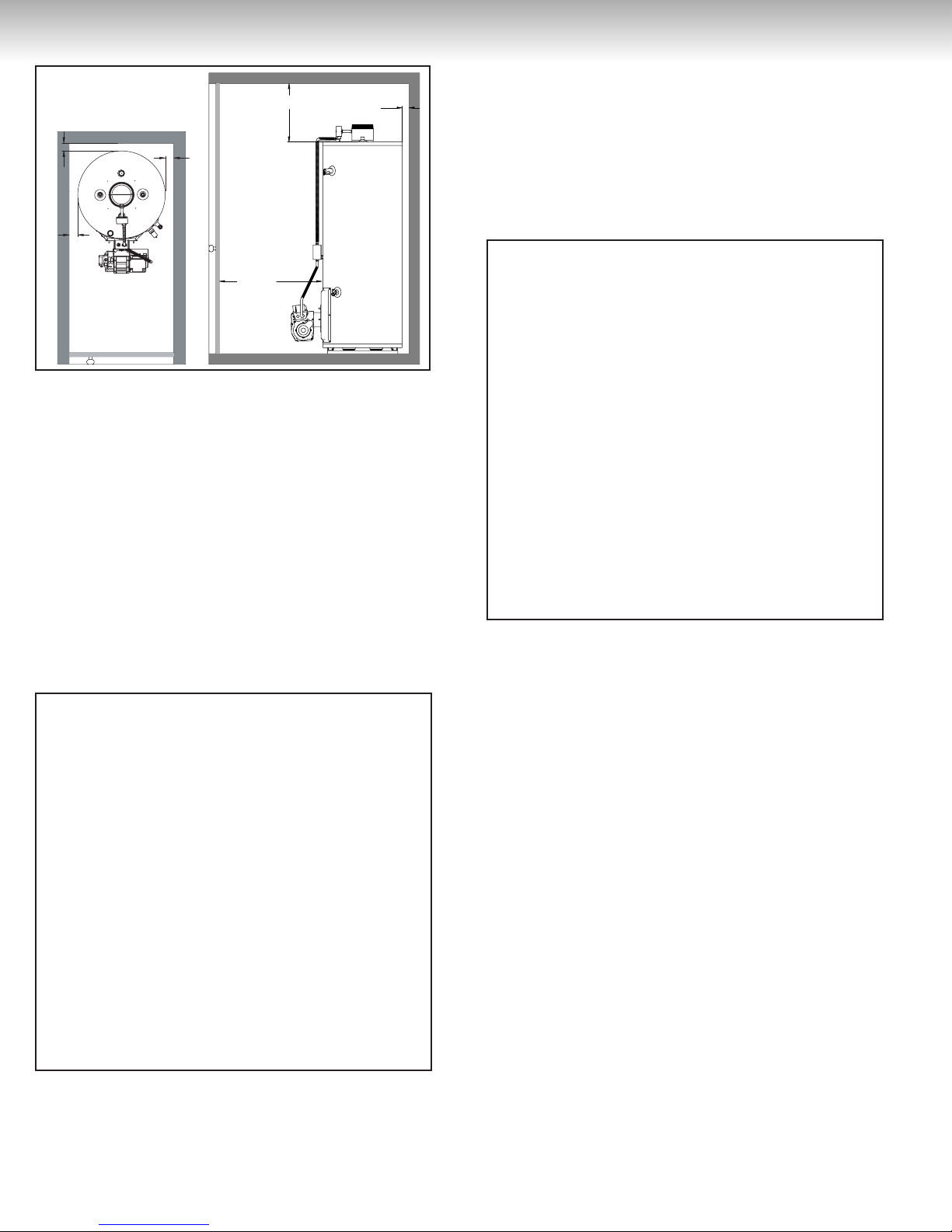
INSTALLATION INSTRUCTIONS
Figure 1
2'' Min.
2'' Min.
Requirements for Unconfined Spaces
Water heaters installed in unconfined spaces do
not usually require outdoor air to function properly. However, if the water heater is located in an
unconfined space in a building having insufficient
infiltration, air for combustion and additional ventilation should be obtained from the outdoors or from
spaces freely communicating with the outdoors (see
Figure 2). Under these conditions, a permanent
opening to the outdoors should be provided so that
the total air received through this opening will be at
least as much as would be admitted by openings having a total free-flow area of one (1) square inch per
5,000 BTU/h (4.4 cm
all oil-fired appliances.
2'' Min.
2
/kWh) of the total input rating of
Figure 2
24'' Min.
18'' Min.
2'' Min.
provided with two permanent openings, one near the
top of the enclosure and another one near the bottom
(see Figure 3). Each opening should have a free-flow
area of not less than one (1) square inch per 1,000
BTU/h (22 cm
2
/kWh) of the total input rating of all
oil-fired appliances in the enclosure, freely communicating with interior areas that have in turn adequate
infiltration from the outdoors.
Figure 3
Requirements for Confined Spaces (Outdoor
Combustion and Indoor Ventilation Air)
A water heater that is located in a confined space
and that obtains its combustion air from outdoors and
ventilation air from within the conditioned space of
the building should be provided with two permanent
openings, one near the top of the enclosure and
another one near the bottom (see Figures 4 and 5).
Each opening should have a free-flow area of not less
than one (1) square inch per 1,000 BTU/h (22 cm
kWh) of the total input rating of all oil-fired appliances
in the enclosure, freely communicating with interior
areas that have in turn adequate infiltration from the
outdoors. A combustion air supply opening to the outdoors should be provided so that the total air received
through the opening will be at least as much as would
be admitted by openings having a total free-flow area
of one (1) square inch per 5,000 BTU/h (4.4 cm
kWh) of the total input rating of all oil-fired appliances
in the enclosure.
2
/
2
/
Requirements for Confined Spaces (Indoor
Combustion and Ventilation Air)
A water heater that is located in a confined space and
obtains all of its air for combustion and ventilation from
within the conditioned space of the building should be
Requirements for Confined Spaces (Outdoor
Combustion and Ventilation Air)
A water heater that is located in a confined space and
that obtains all of its air for combustion and ventilation from outside the building shall be provided with
4

INSTALLATION INSTRUCTIONS
Figure 4
Figure 5
Figure 6
Figure 7
two permanent openings, one near the top of the
enclosure and another one near the bottom (see
Figures 6 and 7). Each opening shall communicate
directly or by means of ducts with the outdoors or
to such spaces (such as a crawl space) that freely
communicate with the outdoors and shall be sized
in accordance with the instructions in the section Air
Duct Sizing.
Air Duct Sizing
The air duct requirements should be met by one of the
following methods:
(a) vertical duct(s) with a free-flow area of not less
than one (1) square inch per 4,000 BTU/h (5.5
2
cm
/kWh) of the total input rating of all oil-fired
appliances in the enclosure;
(b) horizontal duct(s), as shown in Figure 7, with an
equivalent length of less than 50 ft (15 m), having a
free-flow area of not less than one (1) square inch
per 2,000 BTU/h (11 cm2/kWh) of the total input of
all oil-fired appliances in the enclosure; and
(c) air openings that communicate directly with the
outdoors, as shown in Figure 6, having a freeflow area of not less than one (1) square inch per
4,000 BTU/h (5.5 cm2/kWh) of the total input rating of all oil-fired appliances in the enclosure.
Note: Duct runs that are primarily horizontal and
that have an equivalent length greater than 50 ft
(15 m) should be sized larger as required to provide
the same airflow as would be provided by the
requirements of Item (b).
5
Louvers and Grilles
WARNING
In calculating free area for ventilation and combustion air supply openings, consideration must be
given to the blocking effect of louvers, grilles or
screens protecting the openings. Screens must not
be smaller than 1/4 inch (6.4 mm) mesh. If the free
area through a particular design of louver or grille
is known, it should be used in calculating the size
of opening required to provide the free area specified. If the design and free area is not known, it may
be assumed that wood louvers and grilles will allow
20-25% free area and metal louvers and grilles will
allow 60-75% free area. Louvers and grilles must be
installed in the open position or interconnected with
the water heater so that they are opened automatically during water heater operation.
Corrosive Atmospheres
If this water heater is to be installed in a beauty shop,
barber shop, photo processing lab, dry cleaning
establishment, a building with an indoor pool or near
a chemical storage area, it is imperative that the
combustion and ventilation air be drawn from outside
these areas. These particular environments contain products such as aerosol sprays, detergents,
bleaches, cleaning solvents, refrigerants, and other
volatile compounds that, in addition to being highly
flammable, become highly corrosive acid compounds
when burned. Exposure to such compounds can be
hazardous and lead to premature product failure.
Should the water heater fail, due to exposure to
such a corrosive atmosphere, the warranty is
void.
Venting
DANGER
When installing the venting system, make sure to follow all local codes or, in the absence of such codes,
the latest edition of the CAN/CSA B139, Installation
for Oil Burning Equipment, in Canada, and/or the
latest edition of Standard for the Installation of Oil
Burning Equipment, NFPA 31, in the United States.
Never operate the water heater unless it is properly ventilated to the outdoors and has adequate
air supply for proper operation. Failure to properly
install the venting system could result in property
damage, personal injury or death.
Chimney Requirements
If this water heater is operated with a burner designed
for natural draft venting, it must be connected to
a vertical chimney. The chimney must be properly constructed and sized, clean and free of soot,
creosote and obstructions, able to generate suf-
ficient draft to evacuate the products of combustion
outdoors and be lined with a tile or metal liner. Inspect
the chimney and make any repairs necessary before
installing the water heater.
To prevent downdrafts, the chimney flue should
extend at least three (3) feet (1 m) above the highest point at which the chimney comes in contact with
the roof and not less than two (2) feet (0.6 m) above
the highest roof surface or structure within ten
(10) feet (3 m) of the chimney on a horizontal plane
perpendicular to the chimney. Not more than four
(4) inches (100 mm) of chimney flue above the top of
the chimney cap should be considered in computing
this height (see Figure 8). Increase the cross-sectional
area and height of the chimney at least 4% per 1,000
feet (305 m) above sea level.
WARNING
Failure to properly inspect and repair the chimney
could result in property damage, personal injury or
death.
Flue Piping
Before installing the flue piping, make sure that the
venting system layout has been properly planned.
Make sure that the flue baffle has been installed in
the flue tube. If the baffle is not present, immediately
contact the dealer where the water heater was purchased. NEVER operate the water heater without the
flue baffle installed. Verify that the location of the water
heater and the venting system respects all clearances
from combustible materials (see Figure 1).
The length of flue pipe to vent this water heater should
be as short as possible with horizontal runs sloping
upward towards the chimney at a rate of at least
one-quarter (1/4) inch per foot (21 mm/m). Long
horizontal runs of flue pipe, sharp turns and other construction features that could create excessive resistance to the flow of flue gas should be avoided. The
flue pipe must not be smaller in cross sectional area
that the flue collar on the water heater. The flue pipe
must not pass through any floor or ceiling, but may
pass through a wall where suitable fire protection
provisions have been installed. The flue pipe should
connect to the chimney such that it extends into,
and terminates flush with, the inside surface of the
chimney liner. The joint between the flue pipe and
the chimney liner should be sealed and all unused
chimney opening should be closed.
6
 Loading...