

Giant Factories ANSI Z21.10.3, UGTC-152N, CSA 4.3, UGTC-152P, UGTC-199N Owner's Manual
...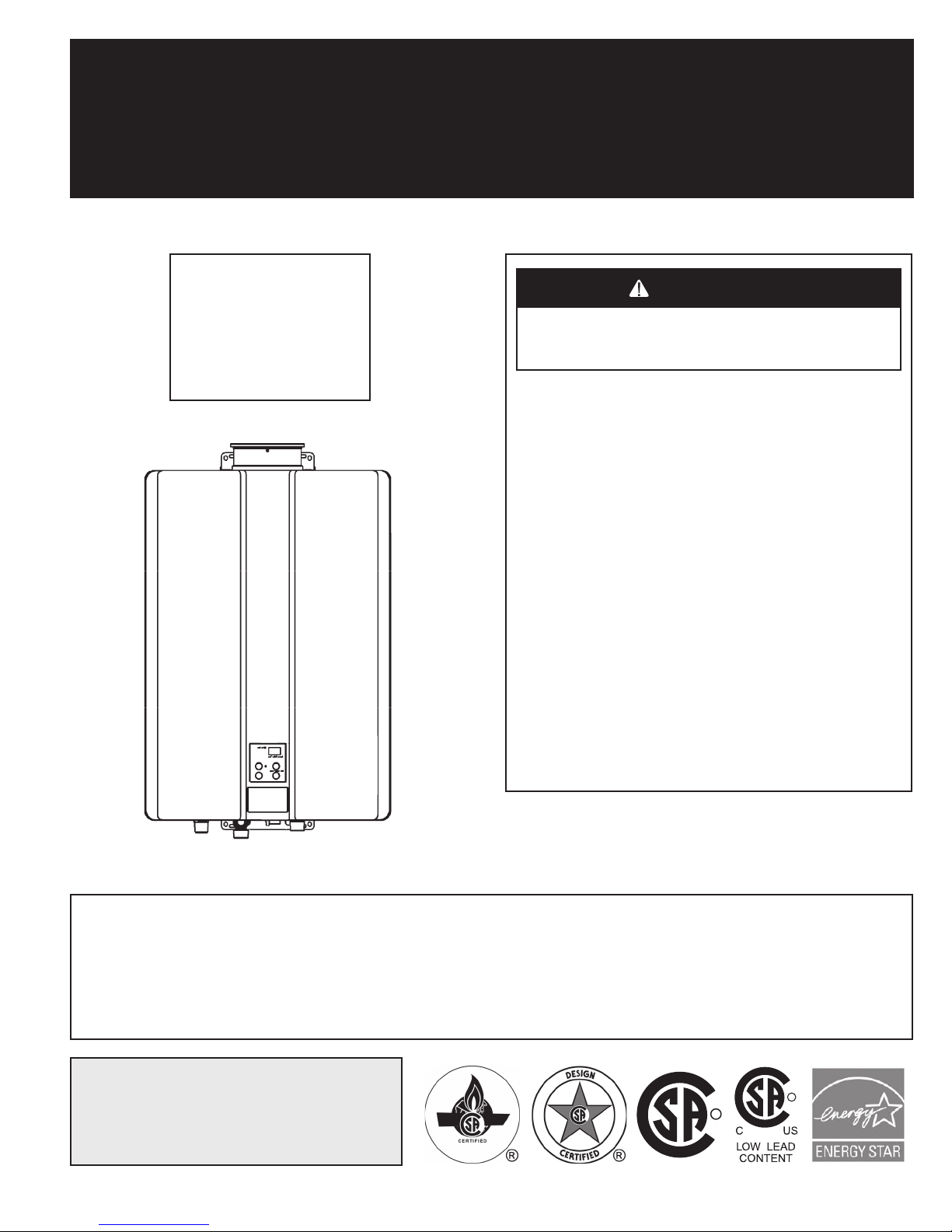
DIRECT VENT TANKLESS WATER HEATERS
R
WARNING
CAUTION
OWNER’S MANUAL
INSTALLATION AND OPERATING INSTRUCTIONS
FOR INDOOR
APPLICATIONS ONLY
UGTC-199N
UGTC-199P
UGTC-152N
UGTC-152P
If the information in these instructions is not followed exactly, a fire or explosion may result causing property damage,
personal injury, or death.
DO NOT
liquids in the vicinity of this or any other appliance.
store or use gasoline or other flammable vapors and
WHAT TO DO IF YOU SMELL GAS:
•
DO NOT
•
DO NOT
•
DO NOT
From a neighbor’s phone, immediately call your gas sup-
•
plier.
• If you cannot reach your gas supplier, call the fire department
Installation and service must be performed by a qualified installer,
service agency or the gas supplier.
try to light any appliance.
touch any electrical switch.
use any phone in your building.
Follow the gas supplier’s instructions.
.
ANSI Z21.10.3 • CSA 4.3
READ ALL OF THE INSTRUCTIONS THOROUGHLY BEFORE INSTALLING OR OPERATING THIS WATER HEATER.
THIS MANUAL PROVIDES INFORMATION ON THE INSTALLATION, OPERATION, AND MAINTENANCE OF THE
WATER HEATER. FOR PROPER OPERATION AND SAFETY IT IS IMPORTANT TO FOLLOW THE INSTRUCTIONS
AND ADHERE TO THE SAFETY PRECAUTIONS. A LICENSED PROFESSIONAL MUST INSTALL THE WATER
HEATER ACCORDING TO THE EXACT INSTRUCTIONS. THE CONSUMER MUST READ THE ENTIRE MANUAL
TO PROPERLY OPERATE THE WATER HEATER AND TO HAVE REGULAR MAINTENANCE PERFORMED.
For your records, write the model and serial number
here:
Model # _________________________________________
Serial # _________________________________________
© 2015 Giant Factories Inc. Printed in Canada
IMPORTANT
R
R
GI-IM045En-1015
TABLE OF CONTENTS
WARNING
CAUTION
DANGER
WARNING
CAUTION
CAUTION
Safety Information .................................2
Safety Behaviors ..................................3
Installation Instructions .............................4
Installer Qualifications ............................ 4
General Instructions .............................. 4
Determine Installation Location ..................... 5
Vent Termination Clearances ....................... 6
Additional clearances ............................. 7
Unit clearances .................................. 8
Freeze Protection ................................ 8
Maximum vent length ............................. 8
Checklist to Determine Installation Location ............ 9
Mount to Wall ................................... 9
Remove the Front Panel ........................... 9
Installation of Venting ............................ 10
Venting Guidelines .............................. 10
Flue Installation with Centrotherm Venting ............ 12
Condensate .................................... 12
Checklist for Venting and Condensate ............... 13
Twin Pipe Venting Guide ...........................13
Installation Instructions .......................... 14
Determine Installation Location .................... 15
Determining Vent Length ......................... 15
Adaptor Installation .............................. 19
Certified PVC/CPVC Vent Termination Options ......... 20
Acceptable Venting Clearances For IPEX Concentric
Vent Kit (CVK) Termination ........................ 22
Venting Installation Sequence ...................... 23
Twin Pipe (PVC/CPVC) Terminations ................ 24
PVC/CPVC Roof (Tee and upside down “U”)
Terminations ................................... 25
NOTE:
Giant sometimes shares customer contact information with businesses that we believe provide products or services that may be
useful to you. By providing this information, you agree that we can share your contact information for this purpose. If you prefer not to
have your information shared with these businesses, please contact customer service and ask not to have your information shared. We will
however, continue to contact you with information relevant to the product(s) you registered and/or you account with us. Should you have
any questions or feel that the manual is incomplete, please contact Giant at 1-800-363-9354.
Installation Instructions (continued) ..................28
Installation of Plumbing .......................... 29
Connect Water Heater to Water Supply ............... 29
Checklist for Plumbing ........................... 29
Installation of Gas Supply ......................... 31
General Instructions ............................. 31
Connect Electricity .............................. 32
Adjust for High Altitude (United States) .............. 32
Adjust for High Altitude (Canada) ................... 32
Adjust for Vent Length ........................... 33
Checklist for Gas and Electricity .................... 33
Installation of Temperature Controller ............... 33
Final Installation Checklist ........................ 34
Technical Data ...................................35
Specifications .................................. 35
Dimensions .................................... 36
Recirculation Mode .............................. 38
Wiring Diagram ................................. 40
Operating Instructions .............................41
Consumer Operation Guidelines for the
Safe Operation of your Water Heater ................ 41
How to Use the Temperature Controller .............. 42
How to Set the Temperature ....................... 42
Troubleshooting Guide ............................44
Diagnostic Codes and Remedies .................... 44
System Maintenance ..............................46
Flushing the Heat Exchanger ....................... 47
Manual Draining of the Water Heater ................ 48
Running a low volume of water through the water heater
to prevent freezing .............................. 48
When the water heater or external piping has frozen .... 48
Regulations ......................................49
Warranty ........................................50
SAFETY INFORMATION
Your safety and the safety of others is extremely important during the installation, operation, and servicing of this water heater. Many safety
related messages have been provided in this manual and on your water heater. Always read and obey all safety messages. These messages
will point out the potential hazard, tell you how to reduce the risk of injury, and tell you what will happen if the instructions are not followed.
This is the safety alert symbol. This symbol alerts you to potential hazards that can kill or hurt you and others.
Indicates an imminently hazardous situation which, if not avoided, will result in serious injury
or death.
Indicates a potentially hazardous situation which, if not avoided, could result in serious injury
or death.
Indicates a potentially hazardous situation which, if not avoided, could result in minor or moderate injury. It may also be used to alert against unsafe practices.
2
SAFETY BEHAVIORS
CAUTION
WARNING
CAUTION
WARNING
CAUTION
• Before operating, smell all around the appliance area for gas.
Be sure to smell next to the floor because some gas is heavier
than air and will settle on the floor.
• Keep the area around the appliance clear and free from combustible materials, gasoline, and other flammable vapors and
liquids.
• Combustible construction refers to adjacent walls and ceiling
and should not be confused with combustible or flammable
products and materials. Combustible and/or flammable products and materials should never be stored in the vicinity of this
or any gas appliance.
• Always check the water temperature before entering a shower
or bath.
• To protect yourself from harm, before performing maintenance:
* Turn off the electrical power supply by unplugging the
power cord or by turning off the electricity at the circuit
breaker. (The temperature controller does not control
the electrical power.)
* Turn off the gas at the manual gas valve, usually located
immediately below the water heater.
* Turn off the incoming water supply. This can be done at
the isolation valve immediately below the water heater
or by turning off the water supply to the building.
• Use only your hand to push in or turn the gas control knob.
Never use tools. If the knob will not push in or turn by hand,
do not try to repair it; call a licensed professional. Force or attempted repair may result in a fire or explosion.
• Do not use this appliance if any part has been under water.
Immediately call a licensed professional to inspect the appliance and to replace any part of the control system and any gas
control which has been under water.
• Do not use substitute materials. Use only parts certified with
the appliance.
• Should overheating occur or the gas supply fail to shut off, turn
off the manual gas control valve to the appliance.
• Do not adjust the DIP switch unless specifically instructed to
do so.
• Do not use an extension cord or an adapter plug with this appliance.
• Any alteration to the appliance or its controls can be dangerous
and will void the warranty.
• BURN HAZARD. Hot exhaust and vent may cause serious
burns. Keep away from the water heater unit. Keep children and
animals away from the unit.
California law requires this notice to be provided:
California Proposition 65
productive harm. This product may contain such substances, be their origin from fuel combustion (gas, oil), or components of the product
itself.
If the information in these instructions is not followed exactly, a fire or explosion may result causing property damage, personal injury, or death.
lists chemical substances known to the state to cause cancer, birth defects, death, serious illness, or other re-
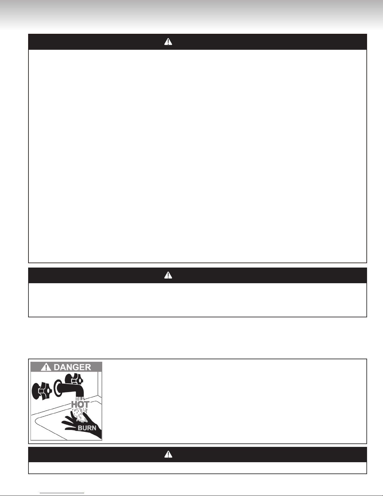
Hot water can be dangerous, especially for infants or children, seniors, or disabled people. There is hot
water scald potential if the thermostat is set too high.
Water temperatures over 125ºF (52ºC) can cause severe burns or scalding resulting in death.
Hot water can cause first degree burns with exposure for as little as:
Three (3) seconds at 140ºF (60ºC)
Twenty (20) seconds at 130ºF (54ºC)
Eight (8) minutes at 120ºF (49ºC)
Test the temperature of the water before placing a child in the bath or shower.
• Hot water outlet pipes leaving the unit can be hot to touch. In
residential applications, insulation must be used for hot water
pipes below thirty-six (36) inches (91.4 cm) due to burn risk
to children.
3
Installer Qualifications
A licensed professional must install, inspect, and leak test the
appliance before use. The warranty will be voided due to improper
installation.
The installer should have skills such as:
• gas sizing
• connecting gas lines, water lines, valves, electricity
• knowledge of applicable national, provincial, and local codes
• installing venting through a wall or roof
If you lack these skills, contact a licensed professional.
Type of installation
• For installation in residential and commercial applications.
• You must follow the installation instructions for adequate combustion air intake and exhaust.
General Instructions
DO NOT
• Do not install the UGTC-152 or the UGTC-199 outdoors.
• Do not install the appliance in an area where water leakage of
the unit or connections will result in damage to the area adjacent
to the appliance or to lower floors of the structure. When such
locations cannot be avoided, it is recommended that a suitable
drain pan, adequately drained, be installed under the appliance.
The pan must not restrict combustion air flow.
• Do not obstruct the flow of combustion and ventilation air. Combustion air shall not be supplied from occupied spaces.
• Do not use this appliance in an application such as a pool or spa
heater that uses chemically treated water. (This appliance is suitable for filling large or whirlpool spa tubs with potable water.)
• Do not use substitute parts that are not authorized for this appliance.
MUST DO
• The installation must conform with local codes or, in the absence of local codes, with the National Fuel Gas Code, ANSI
Z223.1/NFPA 54, or the Natural Gas and Propane Installation
Code, CSA B149.1.
• When installed, the appliance must be electrically grounded in
accordance with local codes or, in the absence of local codes,
with the National Electrical Code, ANSI/NFPA 70, or the Canadian
Electrical Code, CSA C22.1.
• The appliance and its appliance main gas valve must be disconnected from the gas supply piping system during any pressure
testing of that system at test pressures in excess of 1/2 psi (3.5
kPa) (13.84 in W.C.).
• The appliance must be isolated from the gas supply piping system by closing its individual manual shut-off valve during any
pressure testing of the gas supply piping system at test pressures equal to or less than 1/2 psi (3.5 kPa) (13.84 in W.C.).
• You must follow the installation instructions for adequate combustion air intake and exhaust.
INFORMATION
• If a water heater is installed in a closed water supply system,
such as one having a backflow preventer in the cold water supply line, means shall be provided to control thermal expansion.
Contact the water supplier or local plumbing inspector on how
to control thermal expansion.
• Should overheating occur or the gas supply fail to shut off, turn
off the manual gas control valve to the appliance.
• Keep the air intake location free of chemicals such as chlorine
or bleach that produce fumes. These fumes can damage components and reduce the life of your appliance.
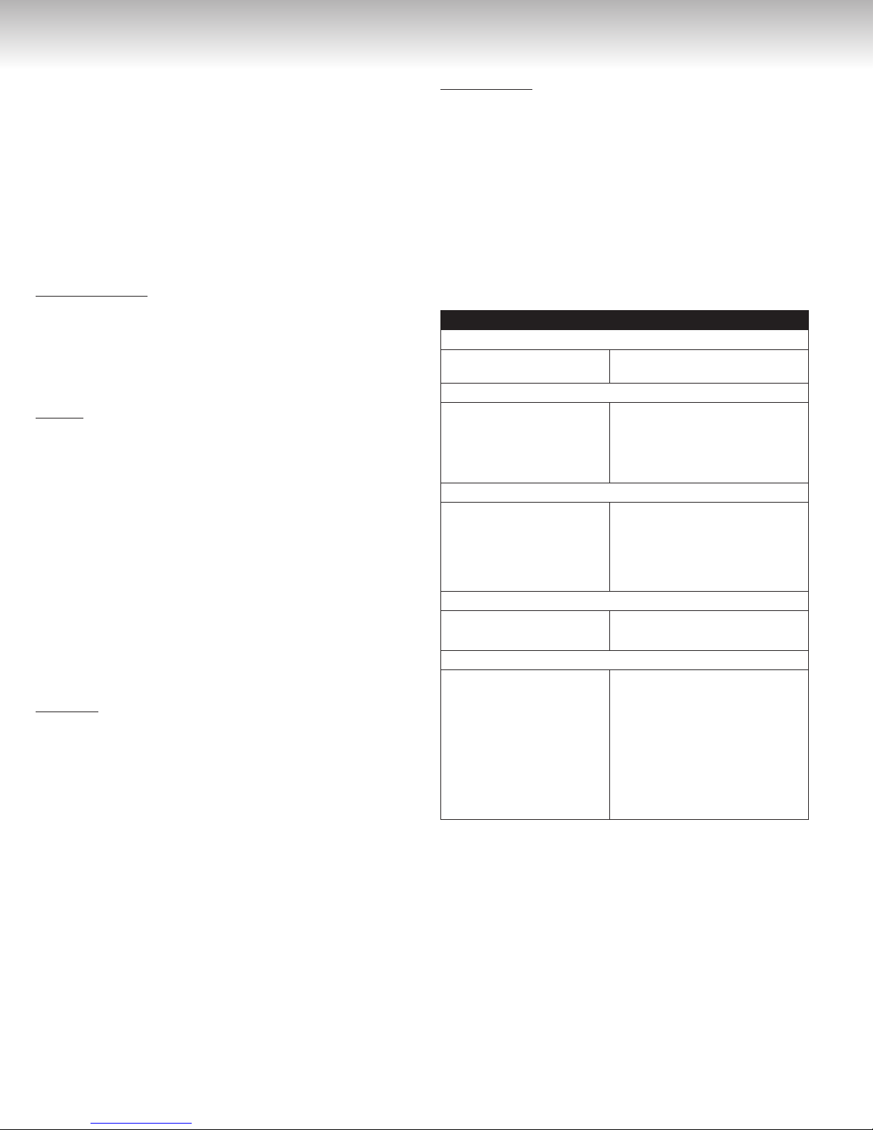
Table 1
Prepare for installation
Parts included
• Tankless water heater
Tools needed
• Pipe wrenches (2)
• Adjustable pliers
• Screwdrivers (2)
• Wire cutters
Tools that might be needed
• Hammer drill with
concrete bits
• Saw
• Threading machine with
heads and oiler
Materials needed
• Soap solution
• Approved venting
Materials that may be needed
• Heat tape
• Pipe insulation
• Electrical wire and conduit
per local code
• Concrete wall anchors
• Optional pipe cover
• Optional temperature
controller
• MC-91-2 temperature controller
(integrated into the front panel)
• Gloves
• Safety glasses
• Level
• Manometer
• Core drill with diamond head
• Torch set
• Copper tubing cutter
• Steel pipe cutter
• Teflon tape (recommended) or
pipe compound
• 5/8” ID PVC flexible tubing
• Two (2) conductor 22 AWG
wires for controller
• Single gang electrical box
• Wire nuts
• Unions and drain valves
4
INSTALLATION INSTRUCTIONS
Determine Installation Location
You must ensure that clearances will be met and that the vent
length will be within required limits. Consider the installation
environment, water quality, and need for freeze protection. Requirements for the gas line, water lines, electrical connection, and
condensate disposal can be found in their respective installation
sections of this manual.
Water Quality
Consideration of care for your water heater should include evaluation of water quality.
Water that contains chemicals exceeding the levels below
will affect and damage the heat exchanger. Replacement
of the heat exchanger due to water quality damage is not
covered by the warranty.
Table 2
Maximum Level
Total Hardness Up to 200 mg / L
Aluminum * Up to 0.2 mg / L
Chlorides * Up to 250 mg / L
Copper * Up to 1.0 mg / L
Iron * Up to 0.3 mg / L
Manganese * Up to 0.05 mg / L
pH * 6.5 to 8.5
TDS (Total Dissolved Solids) * Up to 500 mg / L
Zinc * Up to 5 mg / L
* Source: Part 143 National Secondary Drinking Water Regulations.
If you install this water heater in an area that is known to have hard
water or that causes scale build-up, the water must be treated and/
or the heat exchanger flushed regularly.
IMPORTANT CONSIDERATIONS FOR:
Indoor/Internal Water Heaters and Vent Terminations of
Indoor/Internal Water Heaters
•
DO NOT
contaminated with chemicals.
• Before installation, consider where air has the ability to travel
within the building to the water heater.
• Where possible, install the water heater in a sealed closet so
that it is protected from the potential of contaminated indoor
air.
• Chemicals that are corrosive in nature should not be stored
or used near the water heater.
• Install the water heater termination as far away as possible
from exhaust vent hoods.
• Install the water heater termination as far away as possible from air inlet vents. Corrosive fumes may be released
through these vents when air is not being brought in through
them.
• Chemicals that are corrosive in nature should not be stored
or used near the water heater or vent termination.
Damage and repair due to corrosive compounds in the air is not
covered by warranty.
install in areas where air for combustion can be
When scale build-up in the heat exchanger begins to affect the
performance of the water heater, the diagnostic code “LC #” will
display. Flush the heat exchanger to prevent damage to it. Scale
build-up is caused by hard water set at a high temperature.
Environment
Air surrounding the water heater, venting, and vent termination(s)
is used for combustion and must be free of any compounds that
cause corrosion of internal components. These include corrosive
compounds that are found in aerosol sprays, detergents, bleaches, cleaning solvents, oil based paints/varnishes, and refrigerants.
The air in beauty shops, dry cleaning stores, photo processing
labs, and storage areas for pool supplies often contains these
compounds.
The water heater, venting, and vent termination(s) should not be
installed in any areas where the air may contain these corrosive
compounds. If it is necessary for a water heater to be located in
areas which may contain corrosive compounds, the following instructions are strongly recommended.
54
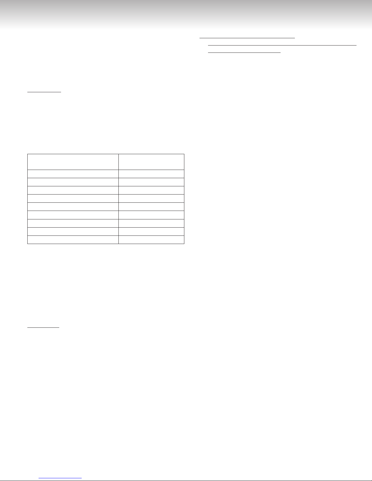
Vent Termination Clearances
X
You must install a vent termination to bring in combustion air and expel exhaust.
Figure 1
TERMINATION
INSIDE
CORNER DETAIL
G
Clearance in
Ref. A also
applies to
anticipated
A
H
snow line
SNOW
I
B
D
E
C
FIXED
B
L
F
CLOSED
OPERABLE
B
B
OPERABLE
B
B
FIXED
CLOSED
J
A
M
K
AIR SUPPLY INLET
VENT TERMINAL
V
AREA WHERE TERMINAL
IS NOT PERMITTTED
The Vent Termination must have a:
A) Clearance above grade, veranda, porch, deck, or balcony
1
Canadian Installations U.S. Installations
12 inches (30 cm) 12 inches (30 cm)
B) Clearance to window or door that may be opened 36 inches (91 cm) 12 inches (30 cm)
C) Clearance to permanently closed window * *
D) Vertical clearance to ventilated soffit, located above the terminal within
a horizontal distance of two (2) feet (61 cm) from the center line of the
* *
terminal
E) Clearance to unventilated soffit * *
F) Clearance to outside corner * *
G) Clearance to inside corner * *
H) Clearance to each side of center line extended above meter/regulator
assembly
3 feet (91 cm) within a
height of 15 feet (4.5 m)
above the meter/ regulator
*
assembly
I) Clearance to service regulator vent outlet 36 inches (91 cm) *
J) Clearance to non-mechanical air supply inlet to building or the combustion
air inlet to any other appliance
K) Clearance to a mechanical air supply inlet
L) Clearance above paved sidewalk or paved driveway located on public
property
M) Clearance under veranda, porch, deck, or balcony 12 inches (30 cm)
36 inches (91 cm) 12 inches (30 cm)
6 feet (1.83 m)
7 feet (2.13 m)
1
*
3 feet (91 cm) above
if within 10 feet (3 m)
*
*
1
A vent shall not terminate directly above a sidewalk or paved driveway that is located between two single family dwellings and serves both dwellings.
* For clearances not specified in ANSI Z223.1/NFPA 54, clearances are in accordance with local installation codes and the requirements of the gas supplier. Clearance to opposite wall is twenty-four
(24) inches (61 cm).
6
INSTALLATION INSTRUCTIONS
Additional clearances
Check on whether local codes supersede these clearances.
• Avoid termination locations near a dryer vent.
• Avoid termination locations near commercial cooking exhaust.
• You must install a vent termination at least twelve (12) inches
(30.5 cm) from the ground.
The vent for this appliance shall not terminate:
• Over public walkways; or
• Near soffit vents or crawl space vents or other area where condensate or vapor could create a nuisance or hazard or cause
property damage; or
• Where condensate or vapor could cause damage or could be
detrimental to the operation of regulators, relief valves, or other
equipment.
nation under a soffit (ventilated or unventilated or eave vent; or
to a deck or porch);
• Do not install vent termination under a soffit vent such that exhaust can enter the soffit vent;
• Install vent termination such that exhaust and rising moisture
will not collect under eaves. Discoloration to the exterior of the
building could occur, if installed too close;
• Do not install the vent termination too close under the soffit
where it could present recirculation of exhaust gases back into
the combustion air intake part of the termination.
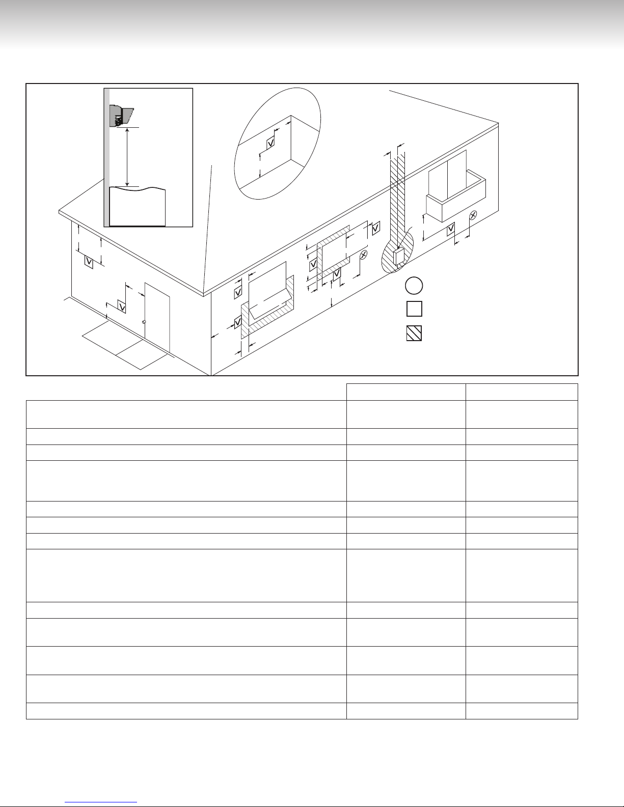
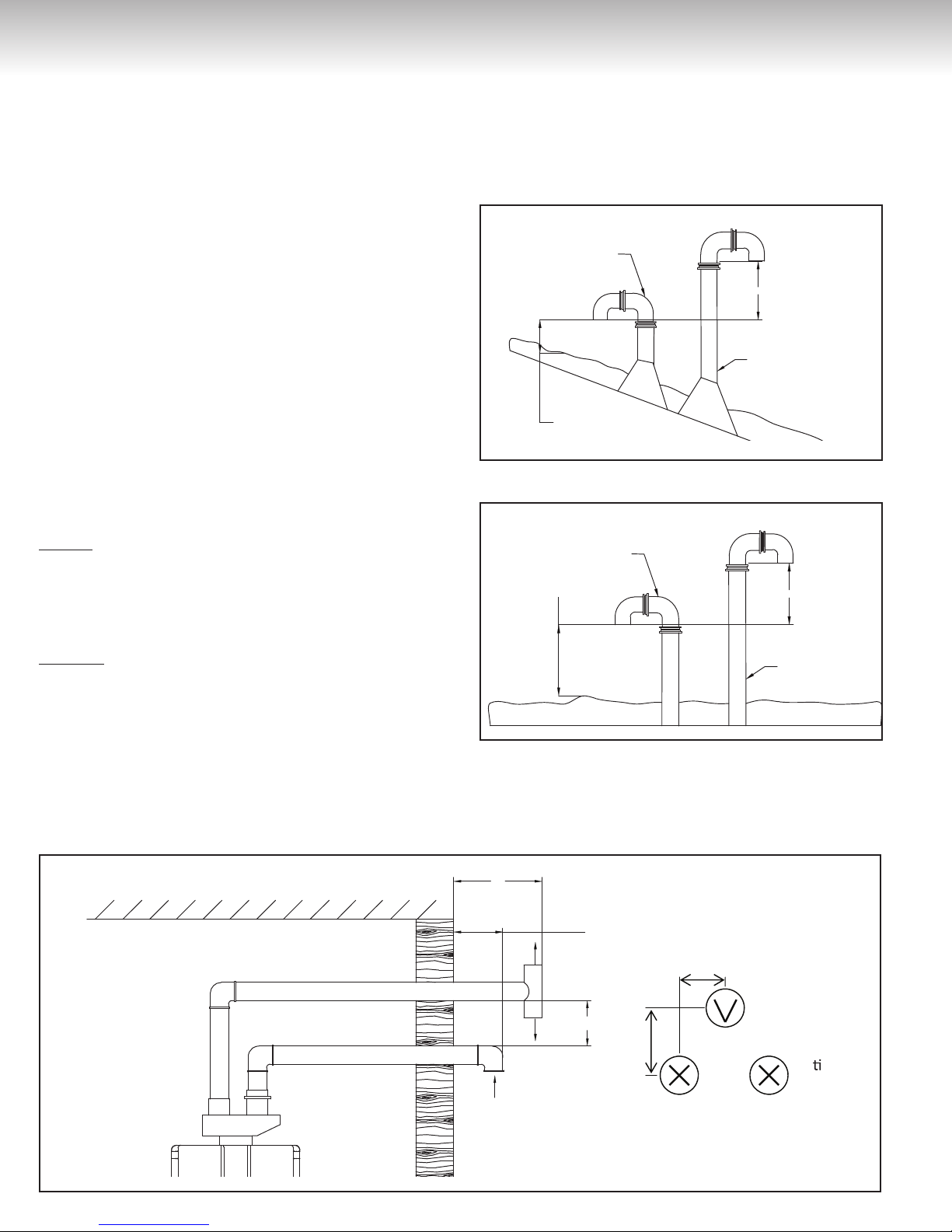
Figure 2
Important considerations
V
(1.5 m)
ver
between
60"
for locating vent termi-
cally
terminals
Figure 3
Figure 4
(30.5 cm) to
an inside
corner
12"
(1.5 m)
between
terminals at
different levels
V
36"
V V
12"
INSIDE
CORNER
60"
(30.5 cm) between
terminals at same
level
V
V
12"
V V
(30.5 cm) between
terminals at same
level
Figure 5
(61 cm) to wall or parapet
24"
V
76
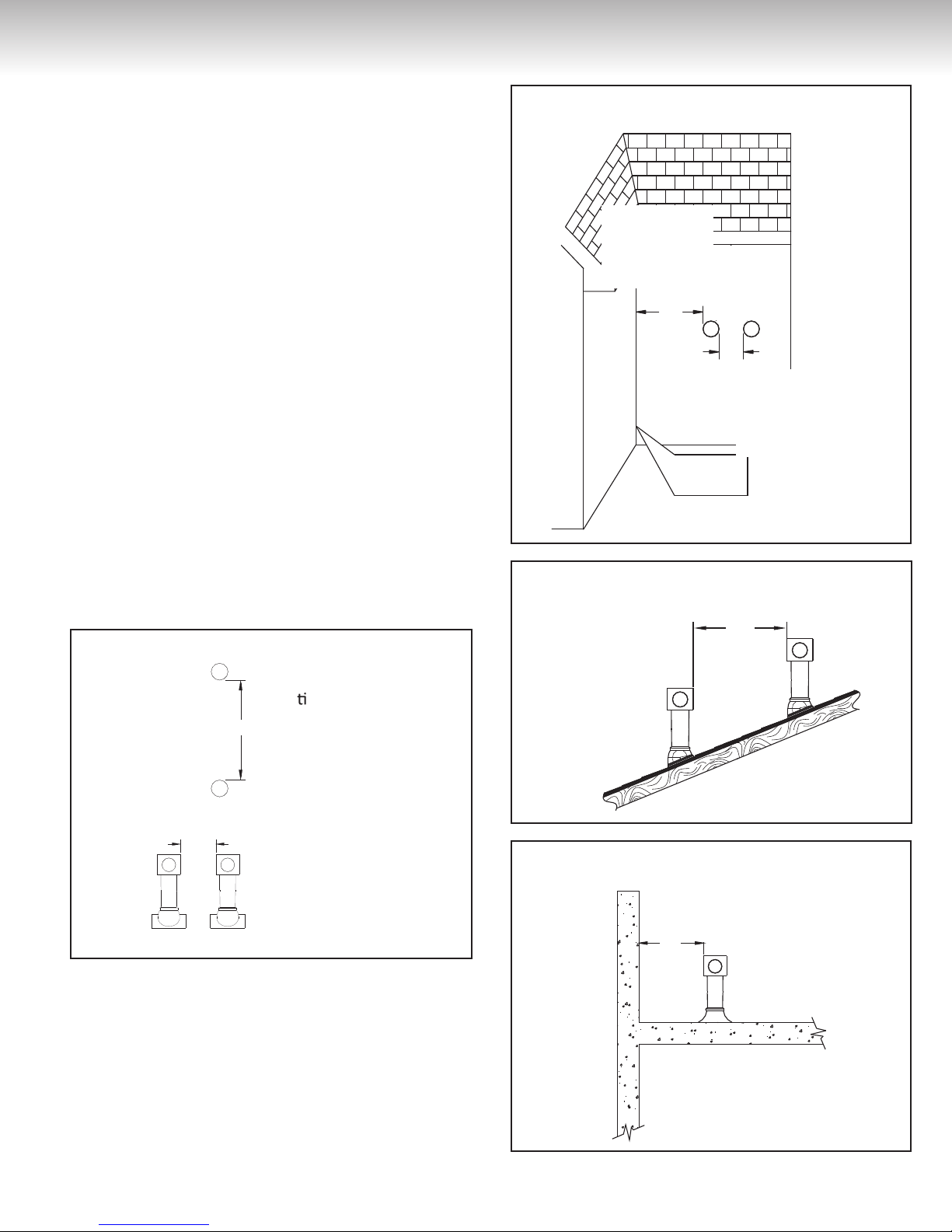
Unit clearances
Figure 6
to top
to front
to side
to floor/ground
Table 3
to Combustibles
inches (cm)
Top of Heater
Back of Heater
Front of Heater
Sides of Heater
Ground/Bottom
Vent
6 * (15.2) 2 *(5.1)
0 (zero) 0 (zero)
6 (15.2) 6 (15.2)
2 (5.1) 1/2 (1.3)
12 (30.5) 12 (30.5)
0 (zero) 0 (zero)
*0 inch from vent components and condensate drain line
The clearance for servicing is twenty-four (24) inches (61 cm) in
front of the water heater.
For closet installation, clearance is six (6) inches (15.2 cm) from
the front.
Freeze Protection
In case of freezing weather, make sure that the water heater and
its water lines are protected to prevent freezing. Damage due to
freezing is not covered by the warranty.
Loss of freeze protection may result in water damage from a burst
heat exchanger or water lines.
With electrical power supplied, the water heater will not freeze
when the outside air temperature is as cold as –22°F (-30°C) for
indoor models,
when protected from direct wind exposure
Because of the “wind-chill” effect, any wind or air circulation on
the unit will reduce its ability to freeze protect.
to Non
Combustibles
inches (cm)
The unit may be drained manually. However, it is highly recommended that drain down solenoid valves are installed that will automatically drain the unit if power is lost. These are available in a
kit, P/N 15000029-A. (The condensate trap drain plug and water
drain plug are not affected by the auto drain down solenoid valves
and will have to be manually opened.)
In addition, the solenoid valves should be connected electrically to
a surge protector with terminals. This allows the solenoid valves
to operate if the water heater is disabled due to a diagnostic code.
The freeze protection features will not prevent the external piping
from freezing. It is recommended that hot and cold water pipes are
insulated. Pipe cover enclosures may be packed with insulation for
added freeze protection.
It is recommended that the condensate trap drain line be insulated.
A frozen condensate trap drain line results in diagnostic code #25.
In the event of a power failure at temperatures below freezing,
the water heater should be drained of all water to prevent freezing
damage. In addition, drain the condensate trap and drain line.
Maximum vent length
Maximum vent length with concentric venting
1) Determine the number of 90-degree elbows in the vent system. (Two (2) 45-degree elbows count as one (1) 90-degree
elbow.)
2) Refer to the table to find the maximum vent length based on
the number of elbows.
Table 4
Number of
900 Elbows
0
1
2
3
4
5
6
Maximum vent length
(concentric venting)
41 ft (12.5 m)
35 ft (10.7 m)
29 ft (8.8 m)
23 ft (7.0 m)
17 ft (5.2 m)
11 ft (3.4 m)
5 ft (1.5 m)
1
2
3
4
4
4
4
3) Adjust switch # 1 in the SW1 DIP switch (tan switches), if
required by the applicable note.
1. If the length is greater than twenty-one (21) feet (6.4 m),
then move switch # 1 (SW1) to OFF.
2. If the length is greater than fifteen (15) feet (4.5 m), then
move switch # 1 (SW1) to OFF.
3. If the length is greater than nine (9) feet (2.7 m), then
move switch # 1 (SW1) to OFF.
4. Move switch # 1 (SW1) to OFF.
.
Example: If you have one elbow, then your maximum
vent length is thirty-five (35) feet (10.7 m). If your actual
length is greater than fifteen (15) feet (4.5 m), then move
switch # 1 (SW1) to OFF.
8
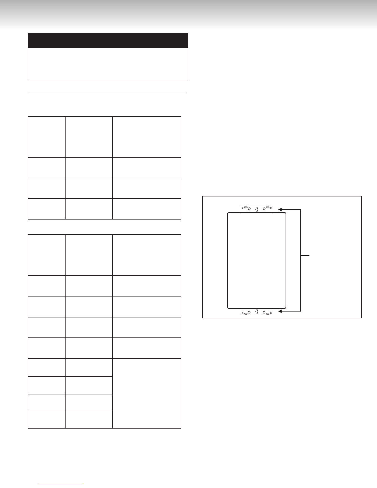
Wall installaon
brackets
INSTALLATION INSTRUCTIONS
Checklist to Determine Installation Location
NOTICE
If you have a longer vent length (see above), switch # 1 is required to be in the OFF position. This ensures the water heater
will run properly. Blocked flue diagnostic codes and shutdowns
may result if switch # 1 is not in the correct position.
Maximum vent length for Centrotherm 2 Pipe InnoFlue Vent System
(single wall SW, 3-inch (7.6 cm) diameter)
Table 5: Vent length using short radius elbow
Number of
90° Short
Radius
Elbows
0
1
2
Maximum
Straight Vent
Length
42 feet
(12.8 m)
27 feet
(8.2 m)
12 feet
(3.7 m)
Switch #1 in the tan
DIP switches
(If length is greater)
18 feet (5.5 m) move
switch #1 to OFF
3 feet (91.4 cm) move
switch #1 to OFF
move switch #1 to OFF
□ The water heater is not exposed to corrosive compounds in
the air.
□ The water heater location complies with the clearances.
□ The planned venting will not exceed the maximum length for
the number of elbows used.
□ The planned venting termination/air intake location meets the
clearances.
□ The water supply does not contain chemicals or exceed total
hardness that will damage the heat exchanger.
□ A standard 3-prong 120 VAC, 60 Hz properly grounded wall
outlet or other 120 VAC, 60 Hz source is available.
□ The installation must conform with local codes or, in the ab-
sence of local codes, with the National Fuel Gas Code, ANSI
Z223.1/NFPA 54, or the Natural Gas and Propane Installation
Code, CSA B149.1.
□
Leave the entire manual taped to the water heater or
give the entire manual directly to the consumer.
Mount to Wall
Figure 7
Table 6: Vent length using long radius elbow
Number of
90° Long
Radius
Elbows
0
1
2
3
4
5
6
7
Maximum
Straight Vent
Length
42 feet
(12.8 m)
27 feet
(8.2 m)
12 feet
(3.7 m)
27 feet
(8.2 m)
21 feet
(6.4 m)
15 feet
(4.5 m)
9 feet
(2.7 m)
3 feet
(91.4 cm)
Switch #1 in the tan
DIP switches
(
If length is greater)
21 feet (6.4 m) move
switch #1 to OFF
15 feet (4.5 m) move
switch #1 to OFF
9 feet (2.7 m) move
switch #1 to OFF
3 feet (91.4 cm) move
switch #1 to OFF
Move switch # 1 to OFF
for any length
1) Identify the installation location and confirm that the in-
stallation will meet all required clearances.
2) Securely attach the water heater to the wall using any
of the holes in the wall installation brackets which are at the
top and bottom of the water heater. Ensure that the attachment strength is sufficient to support the weight. Refer to the
weight of the water heater in the Specifications section. Use
a leveling tool to ensure that the water heater is level. Proper
operation requires that the water heater be level.
NOTE:
The water heater should be installed in an upright position.
Do not install upside down or on its side.
Remove the Front Panel
Slide the plastic trim pieces on each side of the water heater to
expose the screws. Remove the four (4) screws and pull off the
front panel.
98
Installation of venting
Install the correct venting for your model according to the venting
manufacturer’s instruction and the guidelines below (see Table 7
and Table 8). Refer to the manufacturer’s technical literature for
specific part numbers and instructions.
Venting Guidelines
DO NOT
• Do not use cellular core PVC/CPVC, Radel, or galvanized material to vent this appliance.
• Do not combine vent components from different manufacturers.
• Vent diameter must not be reduced.
• Do not connect the venting system with an existing vent or
chimney.
• Do not common vent with the vent pipe of any other manufacturer’s water heater or appliance. Giant water heaters can only
be common vented using a Giant certified common vent system. Common venting is approved for Canadian and U.S. installations.
MUST DO
• This water heater is a direct vent water heater and therefore is
certified and listed with the vent system. You must use vent
components that are certified and listed with the water heater
model.
• The vent system must vent directly to the outside of the building
and use outside air for combustion.
• Avoid dips or sags in horizontal vent runs by installing supports
per the vent manufacturer’s instructions.
• Support horizontal vent runs every four (4) feet (1.2 m) and all
vertical vents run every six (6) feet (1.8 m) or in accordance with
local codes.
• Venting should be as direct as possible with a minimum number
of pipe fittings.
• Vent connections must be firmly pressed together so that the
gaskets form an air tight seal.
• The vent piece connected to the water heater must be secured
with one self-tapping screw.
INFORMATION
• Refer to the instructions of the vent system manufacturer for
component assembly instructions.
• If the vent system is to be enclosed, it is suggested that the design of the enclosure shall permit inspection of the vent system.
The design of such enclosure shall be deemed acceptable by the
installer or the local inspector.
NOTICE
If it becomes necessary to access an enclosed vent system for
service or repairs, Giant is not responsible for any costs or
difficulties in accessing such vent system. The warranty does
not cover obtaining access to a vent system in an enclosed
environment.
Table 7
Manufacturer Listed and Tested Vent Products Telephone Fax Contact
Ubbink
IPEX Concentric/low profile termination kit 866-473-9462 514-769-1672
Centrotherm
Heat-Fab Saf-T Vent SC System 800-772-0739 413-863-4803
Metal-Fab Corr/Guard Vent/Air Intake System 800-835-2830 316-943-2717
Table 8
Manufacturer Product Vertical Termination Horizontal Termination
Ubbink
IPEX Concentric/low profile termination kit
Centrotherm InnoFlue ICRT3539 ISELL0387UV
Heat-Fab Saf-T Vent
Metal-Fab Corr/Guard 3CGRVDK 3CGRVT
Rolux Condensing Vent System
Concentric to Twin pipe adapter
InnoFlue Vent System
(single wall SW, 3-inch (7.6 cm) diameter)
Rolux
PVC/CPVC concentric to twin pipe adapter
800-363-9354 514-640-0969 www.giantinc.com
www.ipexinc.com
sales@ipexinc.com
877-434-3432 518-618-3166
96000050-A 96000051-A, 96000052-A
Saf-T Vent CI Plus
Wall Termination
info@centrotherm.us.com
www.centrotherm.us.com
custsvc@heat-fab.com
www.heatfab.com
info@mtlfab.com
www.metal-fabinc.com
Saf-T Vent CI Plus Rain Cap
10
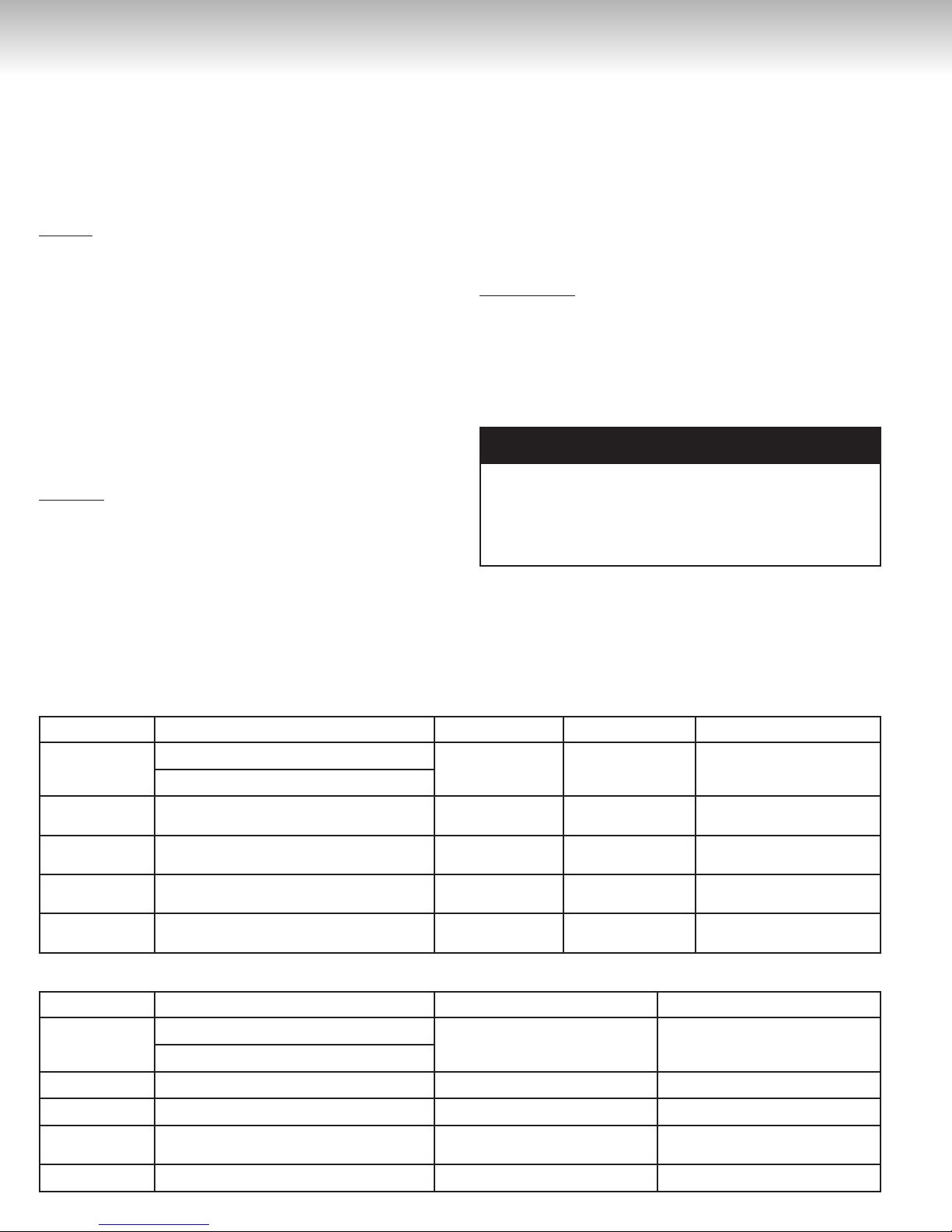
INSTALLATION INSTRUCTIONS
Figure 8
Slope the venting toward the appliance according to the vent
manufacturer’s installation instructions.
Dispose of condensate per local codes.
Horizontal Termination
Vertical Termination
Slope the venting toward the appliance according to the vent
manufacturer’s installation instructions.
Dispose of condensate per local codes.
Securing Screw
Secure the first vent component to the water heater with one selftapping screw at the hole.
1110
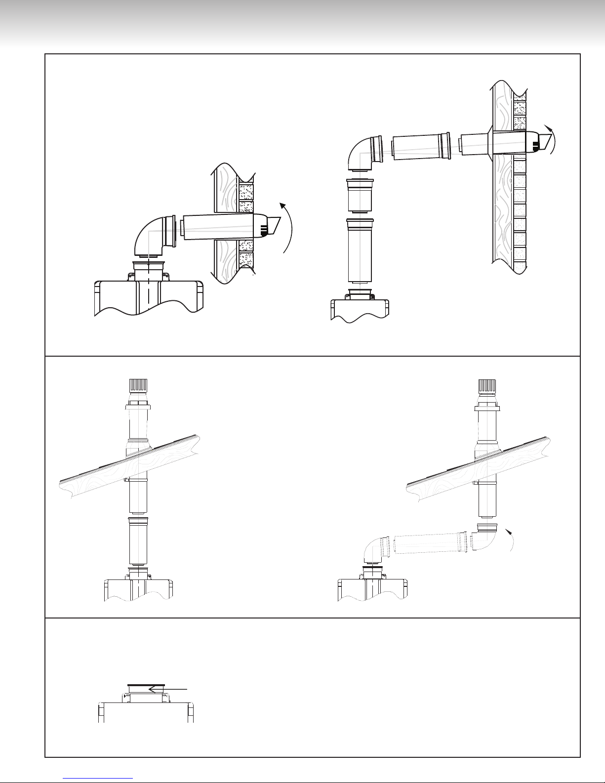
Flue Installation with Centrotherm Venting
Combustion Air pipe
12” (30.5 cm) Minimum
Exhaust Pipe
12” (30.5 cm) Minimum
above anticipated snow level
Exhaust Pipe
12” (30.5 cm) Minimum
Combustion Air Pipe
12” (30.5 cm) Minimum above
anticipated snow level
11”
5”
Admission
Op
onnel
Ven
la on
Échappement
Échappement
Entrée d’air de
combustion
(30,5 cm)
(10,2 cm)
(28 cm)
(12,7 cm)
(20,4 cm)
(30.5 cm)
(10.2 cm)
(20.4 cm)
(28 cm)
(12.7 cm)
11”
5”
Intake
Op
onal
Vent
12”
4”
Exhaust
Exhaust
8”
Install the venting termination according to the diagrams and instructions below.
• Comply with the exhaust clearances found in the Giant Installation and Operating Manual.
• Only one appliance can be attached to the vent system.
• Install the system according to the Centrotherm installation instructions.
• Use the 3”/5” (7.6/12.7 cm) concentric to twin pipe adaptor and
the 3-inch (7.6 cm) diameter venting.
• The vent termination and air intake must be in the same pressure
zone.
• Do not exceed maximum straight vent length with number of
elbows as shown in the following tables.
• Maintain the clearances shown in the following Figures.
Condensate
Condensate formation can occur in high efficiency direct vent
appliances. Without proper drainage condensate will damage the
heat exchanger.
• The condensate drain pipe (along its entire length) must be at
least the same diameter as the drain line, (1/2 inch NPT).
• The end of the condensate drain pipe should be open to the atmosphere. The end should not be under water or other substances.
Figure 10
To prevent condensate damage, follow these instructions.
DO NOT
• Do not connect the condensate drain pipe directly to the rain
sewer.
• Do not connect the condensate drain line with an air conditioning evaporator coil drain.
MUST DO
• Use only vent that is approved and identified as acceptable for
your particular model.
• Slope the venting toward the appliance according to the vent
manufacturer’s installation instructions.
• All condensate must drain and be disposed of according to local
codes.
• Use only corrosion resistant materials for the condensate drain
lines, such as PVC pipe or plastic hose.
Figure 9
Figure 11
12
WARNING
CAUTION
WARNING
CAUTION
TWIN PIPE VENTING GUIDE
INFORMATION
• Water heaters have an integrated condensate collector.
• Regions of cold climate will create more condensate in the vent
system. The condensate collector should be used in cold climates.
• The condensate drain pipe should be as short as possible and
have a downward pitch.
• If the condensate drain gets blocked, a diagnostic code will display on the controller. If this occurs, the condensate drain must
be cleaned.
• The condensate trap will automatically prime (self-prime) during
operation of the unit as condensate forms. Condensate draining
from the unit indicates that the trap is full and that there is no
blockage in the condensate drain. It is not necessary to add water to the condensate trap.
• A condensate neutralizer kit, P/N 50000100-A, is available from
Giant. The kit allows condensate to flow through neutralizing
media that raises the pH of the condensate to a level that will
help prevent corrosion of the drain and public sewer system.
Checklist for Venting and Condensate
□ Verify proper clearances around the vents and air intakes.
□ Ensure you have used the correct venting products for the
model installed and that you have completely followed the
venting manufacturer’s installation instructions as well as
these installation instructions.
□ Verify that the vent system does not exceed the maximum
length for the number of elbows used.
Twin Pipe Venting Guide
The purpose of this guide is to inform about changes with regard
to venting for the following tankless water heater products only:
NOTE
: The Ubbink Concentric to Twin Pipe Adaptor is ULC S636
approved and is listed by the applicable agencies having jurisdiction and is certified for use throughout the U.S. and Canada. The
Concentric to Twin Pipe Adaptor is supplied exclusively through
and/or its distributors.
The newly certified vent system is comprised of a Concentric to
Twin Pipe Adaptor (adaptable to three (3) (7.6 cm) to four (4)
(10.2 cm) sizes), PVC/CPVC pipes, fittings, and either the IPEX
Concentric Vent Kit (CVK) Assembly (System 636), snorkel termination, or tee termination.
NOTICE
PVC venting CANNOT be used with the condensing water
heater, under the following conditions:
• The water heater is installed in a recirculation system and the
thermostat setting is greater than 150˚F (65.5˚C).
• The water heater is used in a combination domestic water and
space heating application which requires a thermostat setting
greater than 150˚F (65.5˚C).
Tankless Water Heaters must be vented and furnished with intake air and exhaust vent using piping and methods described
in this guide and the appliance installation instructions. Each
water heater must have its own intake and vent.
mon vent with any other appliance using this method. Inspect
finished vent and intake air piping thoroughly to ensure all are
airtight and comply with the instructions provided and with all
requirements of applicable codes. Failure to provide a properly
installed vent and air system will cause severe personal injury
or death.
DO NOT
com-
UGTC-199N, UGTC-199P, UGTC-152N, and UGTC-152P
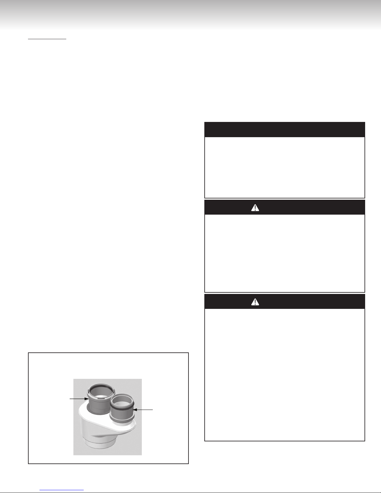
The Ubbink® 3’’/5’’ (7.6/12.7 cm) to 3’’/3’’ (7.6/7.6 cm) Concentric
to Twin Pipe Adaptor (
ment has been certified to be used with the optional PVC/CPVC
twin pipe venting system for both natural and propane units.
Figure 12: Ubbink® 3’’/5’’ (7.6/12.7 cm) to 3’’/3’’
(7.6/7.6 cm) Concentric to Twin Pipe Adaptor
Exhaust Vent
see Figure 12
) and other venting equip-
Combustion Air
Combustion Air Intake
for the condensing tankless water heaters as described in the
Water Heater Manual. The combustion air intake termination fitting must be installed with the clearances and geometry relative
to the exhaust (vent) depicted in this document to ensure that
flue products do not enter the combustion air intake. Ensure
that the intake air will not contain any of the contaminants as
outlined in the “
this document. Contaminated intake air will damage the water
heater, resulting in possible severe personal injury, death, or
substantial property damage.
Exhaust
specified in this guide and as required by all applicable codes.
The exhaust (vent) termination fitting must be installed with the
clearances and geometry relative to the combustion air pipe as
depicted in this document to ensure that flue products do not
enter the combustion air intake.
Determine Installation Location
- Provide exhaust (vent) piping to Water Heater as
- Install combustion air inlet piping
” section of
1312
NOTICE
WARNING
CAUTION
WARNING
CAUTION
WARNING
CAUTION
DANGER
WARNING
CAUTION
If the vent and/or combustion air intake piping configurations
covered in the Water Heater Manual cannot be applied to a specific installation, contact Giant for assistance. Other configurations may be available.
Installations must comply with local requirements and with the
National Fuel Gas Code, ANSI Z223.1/NFPA 54 for U.S. installations or CSA B149.1 for Canadian installations.
cellular core PVC, CPVC, or Radel based pipe materials for the
exhaust vent. Vents
Use only the materials listed in the Water Heater Manual for
vent, combustion air intake pipe, and fittings (see Table 9). Failure to comply with this warning could result in severe substantial property damage, personal injury, or death.
If used, a masonry chimney can ONLY be used as a PIPE CHASE
for the exhaust and combustion air intake pipes. The exhaust
and air piping must be installed as instructed in this guide and
applicable Water Heater Manual. The chimney must be used
only for Water Heater(s) vent chase. NO OTHER appliance or
fireplace can be connected to the chimney. Exhaust and air piping materials must comply with this instruction. The chimney
must be fitted with a sealed access opening to facilitate interior
inspection. The chimney chase (and liner, if installed) to be inspected annually for any degradation. Failure to comply could
result in substantial property damage, personal injury, or death.
MUST
be of solid core pipes ONLY.
DO NOT
use
Installation Instructions
Installation Requirements
• Installation should be performed by a licensed professional.
• All PVC/CPVC IPEX Concentric Vent Kit (CVK) assemblies are
certified to ULC S636. Where ULC S636 compliance is required,
use only System 636 pipe, fittings, and cement at terminal connection.
•
DO NOT
different vent manufacturers, this can result in unsafe conditions
and will void the certification.
•
DO NOT
DO NOT
•
•
DO NOT
solvents and glues have bonded.
• All PVC/CPVC exhaust vent material used in Canada must be
S636 certified.
If the preferred venting option is a twin pipe PVC/CPVC configuration, the approved twin pipe adaptor must be used.
For further details on listed PVC/CPVC venting material (see Table
9) refer to the installation manual of the PVC/CPVC manufacturer.
NOTE:
are all certified as part of the water heater vent system.
Failure to correctly install vent and combustion air intake pipes of
the water heater to atmosphere as outlined in the VENTING section of the Installation Instructions, will result in death from asphyxiation (from carbon monoxide), fire, or explosion.
operate the water heater without proper venting (exhaust and
combustion air intake). Always inspect the vent terminal unit,
combustion air intake pipe, and the entire vent system affixed to
the water heater for proper installation at equipment commissioning and at least annually thereafter.
mix pipe, fittings, cements, or joining methods from
use cellular core PVC, CPVC, nor Radel piping for vent.
use PVC/CPVC on Non-Condensing Units.
operate unit until venting is completely installed and all
The listed vent, vent fittings, termination, cleaner, and glue
NEVER
Table 9: Vent and Air Piping Materials
Item Material
Vent or combustion air
intake pipe & Fittings
PVC pipe cement &
primer
PVC schedule 40 ANSI/ASTM D1785
PVC-DWV ANSI/ASTM D2665
CPVC schedule 40 ANSI/ASTM F441
PVC ANSI/ASTM D2564
CPVC ANSI/ASTM F493
Termination Vent
Screens
Polyethylene
Standard for Installation in North America
United States Canada
Thermoplastic Piping Materials
Thermoplastic vent pipe must be certified to
ULC S636.
Intake pipe may be of any material listed (left).
IPEX bird screens (purchase separately)
Three (3) inch (7.6 cm) Vent screen: IPEX part # 196051;
Four (4) inch (10.2 cm) Vent screen: IPEX part # 196052
(Screens are friction fitted inside termination fitting bells.)
14

TWIN PIPE VENTING GUIDE
Determine Installation Location
Environment
Air surrounding the water heater, venting, and vent termination(s)
is used for combustion and must be free of any compounds that
cause corrosion of internal components. These include corrosive
compounds that are found in aerosol sprays, detergents, bleaches, cleaning solvents, oil based paints/varnishes, and refrigerants.
The air in beauty shops, dry cleaning stores, photo processing
labs, and storage areas for pool supplies often contains these
compounds. Therefore it is recommended that outdoor models be
used for these locations where possible.
The water heater, venting, and vent termination(s) should not be
installed in any areas where the air may contain these corrosive
compounds. If it is necessary for a water heater to be located in
areas which may contain corrosive compounds, the following instructions are strongly recommended.
IMPORTANT CONSIDERATIONS:
•
DO NOT
taminated with chemicals.
• Before installation, consider where air has the ability to travel
within the building to the water heater.
• Where possible, install the water heater in a sealed closet so
that it is protected from the potential of contaminated indoor air.
• Chemicals that are corrosive in nature should not be stored or
used near the water heater.
• Locate the vent outlet where flue gases will not harm surrounding plants and/or cooling equipment. All vent locations must adhere to the recommended vent/combustion air intake terminal
position as outlined in Table 3.
• Avoid locating vent where prevailing winds could affect the performance of the water heater or cause recirculation of the flue gases.
•
DO NOT
an area where condensate or vapor can create a nuisance / hazard or where condensate can be detrimental to the operation of
equipment such as regulators or relief valves.
• Water Heater flue gases must be piped from the appliance to
the outside, installer MUST adhere to the instructions provided
herein and the most recent Water Heater Manual and all applicable codes.
• The exhaust and combustion air must terminate through the
same sidewall or roof as the terminations must be in the same
pressure zone and face the same direction.
• The vent pipe must terminate either through the sidewall or
through the roof, exhaust/vent termination and/or intake air
openings shall adhere to clearances as set forth in the Direct
Vent Termination Clearances diagram.
• Each Condensing Tankless Water Heater requires a separate
vent system.
• If common venting is required, refer to common Vent Installation Manual (latest revision) for instructions on optional venting
method as well as to verify which tankless models may be common vented.
• Use only PVC/CPVC three (3) inch (7.6 cm) and four (4) inch
(10.2 cm) Venting.
install in areas where air for combustion can be con-
terminate the venting over a public walkway or over
Damage and repair due to corrosive compounds in the air is not
covered by warranty.
For PVC/CPVC vent systems reduce the maximum allowable length
for each elbow and termination type as follows and as referenced
in
Tables 11-14
Exhaust and Combustion Air Intake Pipe Diameters and Max
Lengths:
• For PVC/CPVC vent systems reduce the maximum allowable
length for each elbow and termination type as follows:
* 2.5 feet (76.2 cm) for every 45° elbow.
* 5 feet (1.5 m) for every 90° elbow.
* Termination.
• Exhaust and combustion air intake pipe diameters to be as specified in
• Do not exceed exhaust and combustion air intake pipe MAXIMUM lengths as outlined in
(Lengths are specific to models and fuel type).
Additional Clearance Requirements:
• Avoid termination locations near a dryer vent.
• Avoid termination locations near commercial cooking exhaust.
• Install vent termination at least twelve (12) inches (30.5 cm)
above grade or anticipated snow level.
Vents shall not terminate:
• Over public walkways; or near soffit vents or crawl space vents
or other area where condensate or vapor could create a nuisance
or hazard or cause property damage.
• Where condensate or vapor could cause damage or could be
detrimental to the operation of regulators, relief valves, or other
equipment.
Important considerations for locating vent termination under a
soffit (ventilated or unventilated or eave vent; or to a deck or
porch):
•
DO NOT
exhaust can enter the soffit vent.
• Install vent termination such that exhaust and rising moisture
will not collect under eaves. Discoloration to the exterior of the
building could occur if installed too close.
•
DO NOT
where it could present recirculation of exhaust gases back into
the combustion air intake part of the termination.
Determining Vent Length
There are two options for determining the vent lengths/components necessary for the installation.
Option 1:
Option 2:
of this document:
Tables 11-14
install vent termination under a soffit vent such that
install the vent termination too close under the soffit
The installer can use the vent length calculation sheet,
filling in the quantity of the vent components in order
to calculate the total equivalent vent lengths.
The installer can use the maximum vent length tables
on the next pages to determine the amount of straight
pipe that can be used with a specific termination type
and quantity of elbows.
of this document.
Tables 11-14
of this document.
1514
OPTION 1:
CAUTION
Calculation of equivalent piping lengths for venting system:
Choose the vent type and fill out the following table. When determining equivalent combustion air and vent length, add five (5) feet
(1.5 m) for each 90° elbow, 2.5 feet (76 cm) for each 45° elbow.
Example of calculation
(assume three (3) inch (7.6 cm) diameter pipes for natural gas
unit):
• Twin pipe (parallel) with snorkel terminal
• Combustion air pipe length: forty (40) feet (12.2 m) straight pipe
with three (3) x 90° elbows
• Exhaust pipe length: forty (40) feet (12.2 m) straight pipe with
three (3) x 90° elbows (include all interior and exterior elbows)
• Snorkel Termination: ten (10) equivalent feet
Calculation:
• Equivalent Combustion air pipe length: [40+(3 X 5)+10] = 65
feet (19.8 m)
• Equivalent Vent Length: [40+(3 X 5)+10] = 65 feet (19.8 m)
• Total = 65 feet (19.8 m) for both exhaust and combustion air
pipes, which is the maximum allowable vent length for three (3)
inch (7.6 cm) PVC/CPVC on a natural gas unit. If longer lengths
are required, go to the four (4) inch (10.2 cm) diameter pipe
configuration which is certified for up to one hundred (100)
equivalent feet.
(see Table 11)
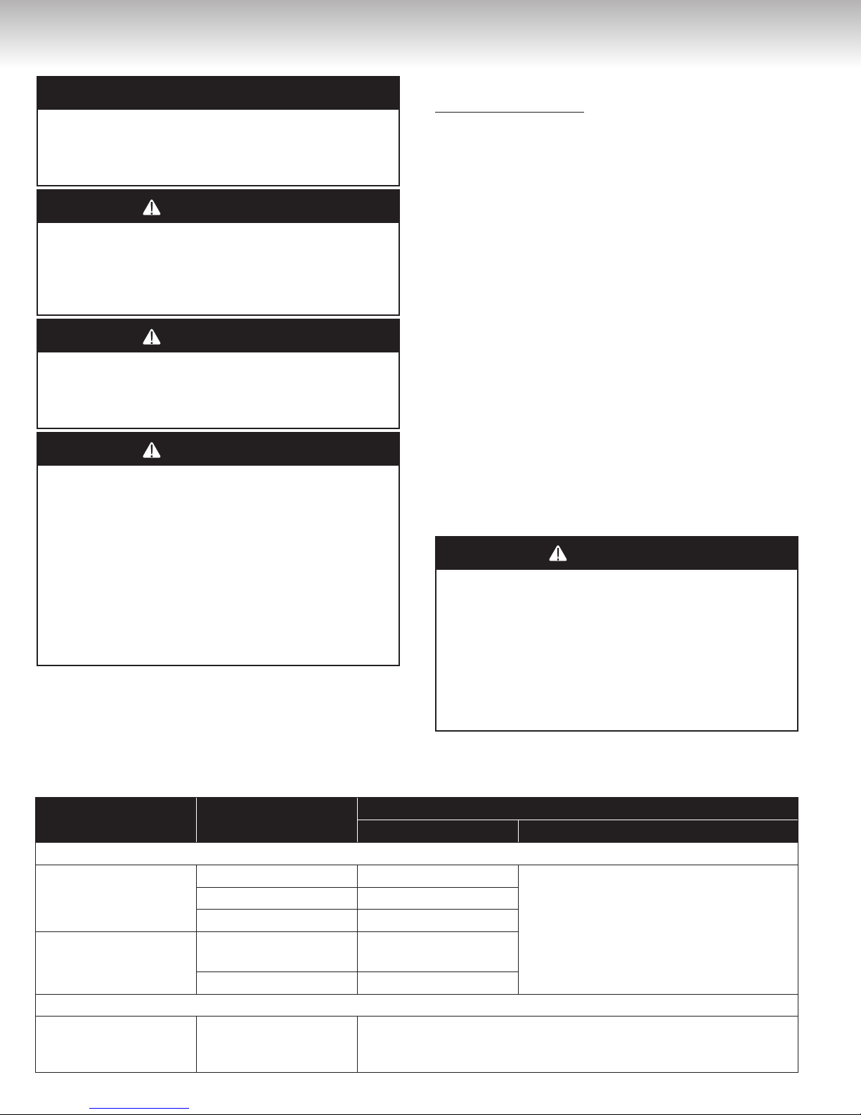
Maximum equivalent vent lengths are specific to the fuel type
of the tankless water heater. It is imperative when performing
equivalent vent length calculations, that the following be taken
in consideration:
Natural Gas Units
Vent Type
3” (7.6 cm)
PVC/CPVC
Concentric PP 65 Feet (19.8 m) 41 Feet (12.5 m)
4’’ (10.2 cm)
PVC/CPVC
Twin Pipe PP
(Centrotherm)
OPTION 2:
Maximum Equivalent Vent Length Tables:
1) Determine the number of 90-degree elbows in the vent system. (Two (2) 45-degree elbows count as one (1) 90-degree
elbow.)
2) Refer to Tables 11-14 to find the maximum vent length based
on the number of elbows and termination style.
Maximum Equiva-
lent Vent Length
65 Feet (19.8 m) 41 Feet (12.5 m)
100 Feet (30.5 m) 65 Feet (19.8 m)
41 Feet (12.5 m) 41 Feet (12.5 m)
Propane Units
Maximum Equiva-
lent Vent Length
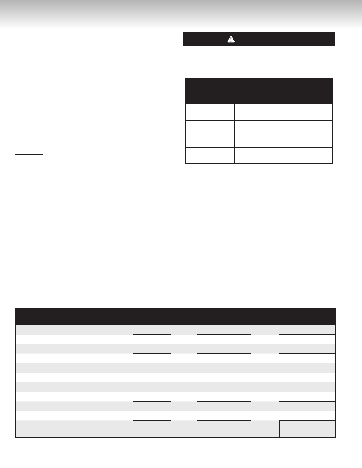
Table 10: Equivalent Vent Length Calculation Sheet
Fitting / Termination Type
1) 900 elbow 3
0
2) 45
elbow
3) IPEX Low Profile Termination
4) IPEX 4’’ (10.2 cm) Concentric Termination
5) IPEX 3’’ (7.6 cm) Concentric Termination
6) 3’’ (7.6 cm) Tee Termination
7) 4’’ (10.2 cm) Tee Termination
8) 3’’ (7.6 cm) Snorkel Termination 1
9) 4’’ (10.2 cm) Snorkel Termination
10) Length of Straight Section in feet NA
(A blank copy of the Vent Length Calculation Sheet is located at the end of this section)
Ensure switch #1 in the bank of eight (8) tan dip switches is in OFF position if vent length is greater than twenty-one (21) feet (6.4 m).
Number of
fittings
x
x
x
x
x
x
x
x
x
x
16
Equivalent Vent
Length
5
2.5
5
20
20
5
5
10
10
40
Total (add up
lines 1 through 10)
=
=
=
=
=
=
=
=
=
=
Total Equivalent
Length
15
0
0
0
0
0
0
10
0
40
65
 Loading...