

Page 1

Instruction manual
Index
General recommendations
Safety warnings ..................................................................................... 2
Tools and equipment ............................................................................. 2
Trinity Advanced SL features..................................................................... 3
Operations prior to assembly
How to select the right frame size ? ...................................................... 5
How to acheive the right position ?........................................................ 7
Headset Instruction .................................................................................. . 7
Assembly Instruction............................................................................ . 8
AeroDrive Cockpit .................................................................................... . 9
Overview.............................................................................................. . 9
How to proceed ?................................................................................. . 9
Parts listing ..........................................................................................10
AeroDrive Stem Introduction ............................................................... 11
AeroDrive size selection ...................................................................11
Armrest and extensions.......................................................................13
Armrest height adjustment................................................................ 13
Extensions adjustment...................................................................... 14
Armrest pads adjustments................................................................ 15
Armrest pads width adjustment ........................................................ 16
Armrest pads orientation adjustment................................................ 17
AeroDrive base bar
Cable specification............................................................................... 19
Fork cable routing ............................................................................. 19
Base bar cable routing...................................................................... 20
Brake cable and housing ..................................................................21
Index cable and housing................................................................... 22
Assembly Instruction............................................................................ 23
Disassembly Instructio
Cable replacement instruction ................................................................. 26
Vector SLR Seat post & seat clamp.........................................................27
Saddle clamp offsets ...........................................................................27
Saddle height adjustment .................................................................... 28
Speed Control braking system................................................................. 29
SpeedControl system introduction....................................................... 29
SpeedControl brake levers .................................................................. 29
Installation instruction. ......................................................................30
SpeedControl brake calipers ............................................................... 31
Installation instruction: ......................................................................32
Brake pads replacement instruction. ................................................ 33
Derailleur hangers.................................................................................... 34
Front derailleur replaceable hanger plate............................................ 34
Rear derailleu
PowerCore press-fit bottom bracket ........................................................ 35
Installation............................................................................................35
Removing.............................................................................................36
Warranty .............................................................................................. 36
and upper stem preparation ............................. 18
n....................................................................... 26
r replaceable dropout hanger........................................ 34
General recommendations
Safety warnings
Warning and Caution description
Tools and equipment
We recommend using the following products :
Recommended torque values mustGIANT torque wrenches :
- 4Nm TORQKEY
- 6Nm TORQKEY
Grease : PTFE
1
2
Page 2
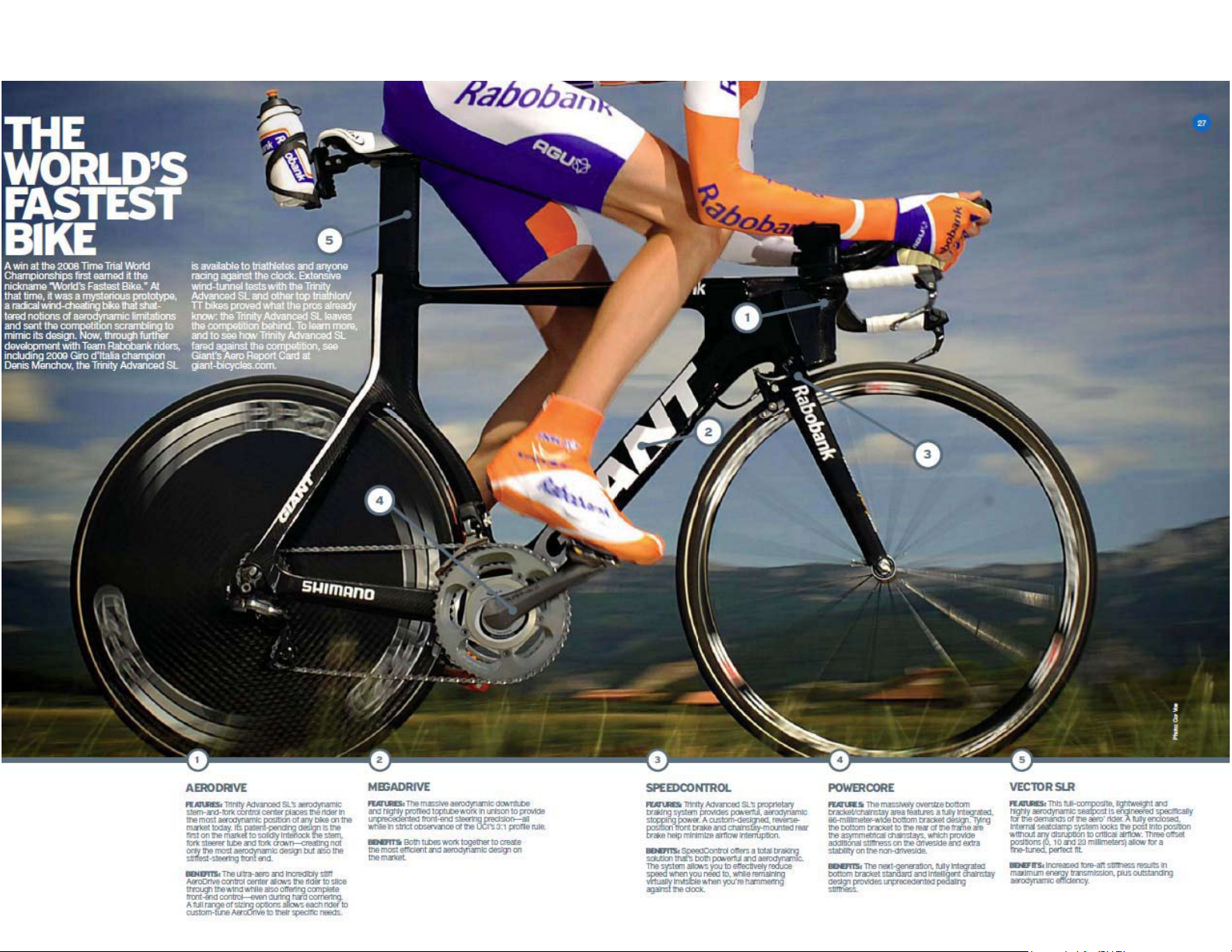
Trinity Advanced SL features
5
3
6
4
Page 3
Operations prior to assembly
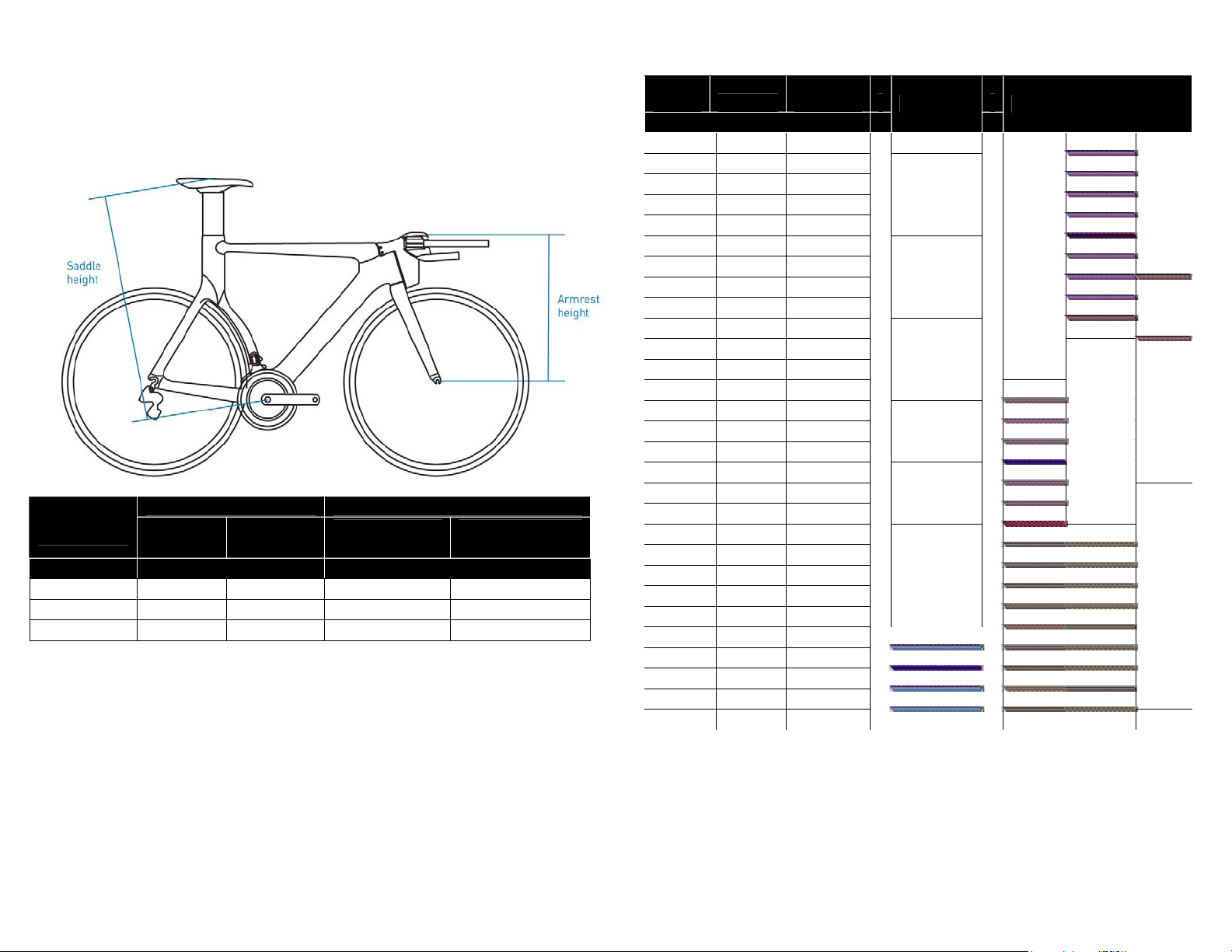
How to select the right frame size ?
The most accurate way to chose from one of the three sizes available is to
refer to the table below.
Please refer to the armrest height to select your frame size.
FRAME
SIZE
S 65 75
M 74 81
L 80 89
If you are not sure about your armrest height, you can still refer to this basic
size table.
This recommendation helps you to select approximately your frame size
from:
- your height
- your inseam
- your saddle height
- your actual TCR frame size
SADDLE HEIGHT
mini max
(centimeters) (centimeters)
ARMREST HEIGHT
Low stem
no spacer
42,9 54,9
45,8 57,8
48,7 60,7
High stem
40mm of spacers
RIDER
SIZE
159,3 73,0 65,0
161,0 74,0 65,9
162,8 75,0 66,8
164,5 76,0 67,6
166,3 77,0 68,5
168,0 78,0 69,4
169,8 79,0 70,3
171,5 80,0 71,2
173,3 81,0 72,1
175,0 82,0 73,0
176,8 83,0 73,9
178,5 84,0 74,8
180,3 85,0 75,7
182,0 86,0 76,5
183,8 87,0 77,4
185,5 88,0 78,3
187,3 89,0 79,2
189,0 90,0 80,1
190,8 91,0 81,0
192,5 92,0 81,9
194,3 93,0 82,8
196,0 94,0 83,7
197,8 95,0 84,6
199,5 96,0 85,4
201,3 97,0 86,3
203,0 98,0 87,2
204,8 99,0 88,1
206,5 100,0 89,0
208,3 101,0 89,9
INSEAM
(centimeters)
SADDLE
HEIGHT
TCR TRINITY ADV SL
XS/43
S
S/46,5
M/50
M-L/53,5
L/55,5
XL/58,5
M
L
5
6
Page 4
How to acheive the right position?
1. Saddle height
The saddle height is basically determined by this calculation:
RIDER INSEAM x 0,89 = SADDLE HEIGHT
Headset Assembly Instruction
Mounting crown race on fork steerer:
1. Ensure that fork steerer is clean and free of metal chips, dirt and
paint.
2. AeroDrive
A previous bike setup could be adapted to the Trinity Advanced SL.
Otherwise, we do recommend starting with the high position stem and
all the highest armrest position.
By setting up the AeroDrive as high as possible, you can progressively
lower the position by changing the stem.
Then, you can fine tune your setup by removing some extension
spacers.
With this procedure, you will save some time and money by avoiding
changing the cables every time you try a new position. -
Once the bar position defined, report to the different parts of this manual
to assemble your setup.
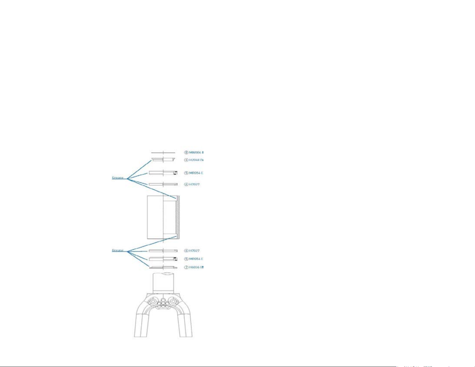
Headset Instruction
FSA N°26G2 1”1/8
The TRINITY Advanced SL
AeroDrive uses a classic FSA
headset but without the conical cap,
as the stem integrates it’s own top
cap.
Please closely follow the assembly
instructions. Any failure in the
assembly could result in serious
injury or death.
Grease elements as indicated on the
figure.
2. Apply a thin layer of grease to the crown race seat on the fork
steerer.
3. Tap the crown race on to the steerer using a crown race installation
tool.
Note: Use the correct fitting on the installation tool to ensure no damage is
done to the crown race.
4. Apply a thin layer of grease to bearings, cups, races and
compression rings.
Integrated models only, insert bearings directly into headtube
bearing seat.
5. Slide fork steerer through the headtube.
6. Slide upper bearing race compression ring on to steerer and seat
against upper bearing.
7. Slide upper top cap compression ring on to steerer.
8. Slide top cap on to steerer. Ensure that the integrated cable housing
is facing forward.
stop
9. Install any headset spacers and stem.
10. Install compression device or star-fangled nut and top cap.
Important: A star-fangled nut should never be installed in a carbon
steerer, use only a compression device such as the FSA
Compressor.
11. Adjust bearing preload by tightening the top screw only until all play
is absent from head assembly and bearings spin freely. Important:
The top screw is for bearing preload only. It is not a fastening screw.
Damage may occur if the top screw is tightened beyond proper
bearing preload.
12. Tighten stem bolts according to the AeroDrive stem assembly
(report to AeroDrive cockpit instruction).
Figure 1 : FSA N°26G2 headset
detail
7
8
Page 5
AeroDrive Cockpit
Overview
AeroDrive is a completely integrated stem, base bar and extension set. None
of the parts included are to be substituted.
The stem is the most critical element. It’s a set consisting of a lower stem
and an upper stem. Three stem sets are provided: low, middle, high.
How to proceed ?
1. Find out your base bar height => select the appropriate AeroDrive
stem
2. fFnd out your armrest height => calculate the spacer height you
need to assemble
3. Assemble the AeroDrive cockpit
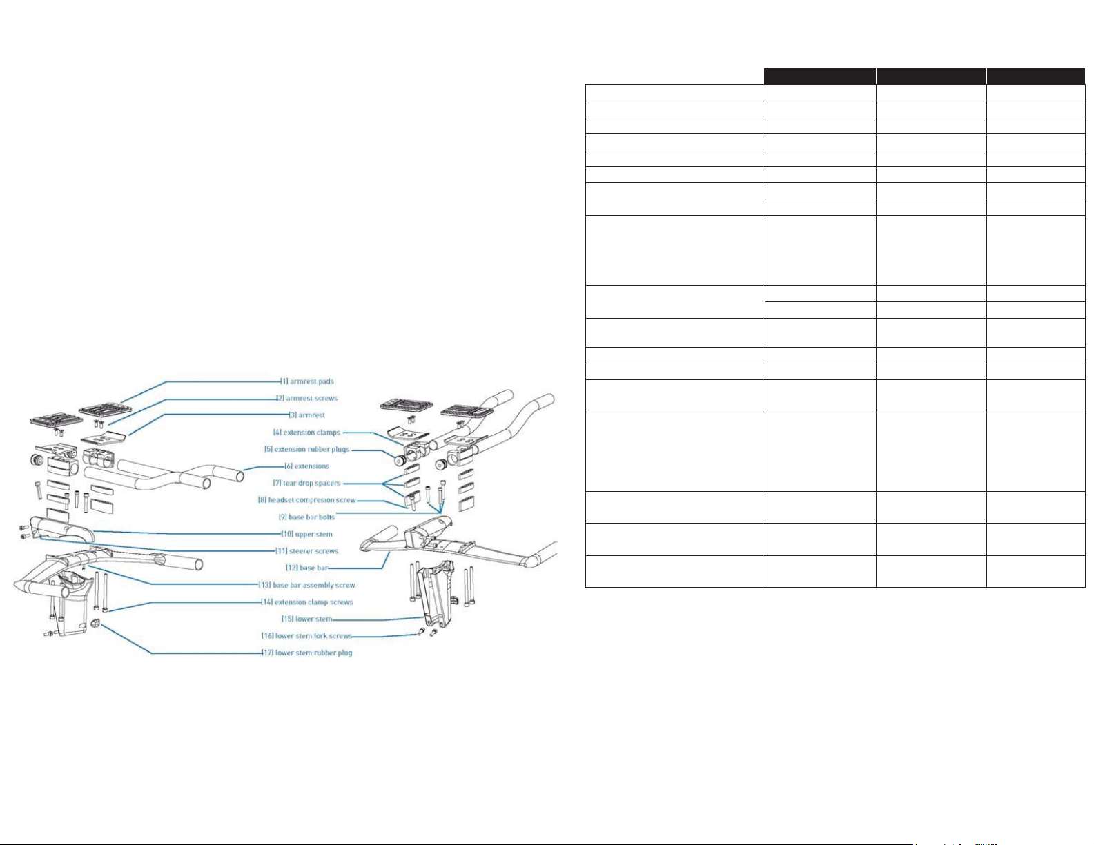
Parts listing
Specification Quantity
[2] armrest screws M5x6 tapered 4 4 Nm
[7] tear drop spacers
[8] headset compression
screw
[9] base bar screws
[11] steerer screws M5x16 2x 6 Nm
[13] base bar assembly
screw
[14] extension clamp
screws
[15] lower stem 3x (low +
[16] lower stem fork
screws
[17] lower stem rubber
plug
10mm 4 20mm 2 M6x30 1x For bearing
M5x30 2x 6 Nm
M6x35 1x 6 Nm
low + middle + high
M4x30 1x 4 Nm
M6x75 (40mm)
M6x65 (30mm)
M6x55 (20mm)
M6x45 (10mm)
M6x35 (0mm)
middle + high)
M5x16 2x 6 Nm
x3 mets reppu ]01[
4x 6 Nm
Torque range
- 2 sdap tsermra ]1[
- 2 tsermra ]3[
- 2 spmalc noisnetxe ]4[
- 2 sgulp rebbur noisnetxe ]5[
- 2 snoisnetxe ]6[
adjustment.
Report to
headset
instruction
-
- 1 rab esab ]21[
-
- 1
Figure 2 : AeroDrive exploded view & designations
9
10
Page 6
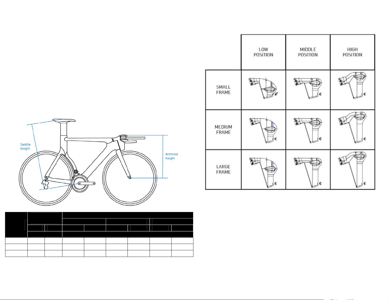
AeroDrive Stem Introduction
AeroDrive size selection
The AeroDrive system is provided with three different stems :
- Low (-40mm)
- Middle (0mm)
- High (+40mm)
With this three stem set, you can adjust your base bar height by +/-40mm. A
total range of 80mm for each frame size is possible.
In addition to this, you can add up to 4mm of teardrop washers to space your
armrest over the base bar.
Similar to the table used to select the appropriate frame size, here is some
additional information to select your stem size.
SADDLE
FRAME
SIZE
S 65 75
M 74 81
L 80 89
HEIGHT
mini max
(centimeters)
ARMREST HEIGHT
LOW STEM MIDDLE STEM HIGH STEM
min
42,9
45,8
48,7
max
46,9 46,9 50,9 50,9
49,8 49,8 53,8 53,8
52,7 52,7 56,7 56,7
min
(centimeters)
max min
11
Figure 3 : AeroDrive stem range
max
54,9
57,8
60,7
12
Page 7

Armrest and extensions
Armrest height adjustment
The armrest supports
height can be
adjusted up to 40mm
with the teardrop
spacers.
Depending on the
selected height, make
sure you are using the
correct screw length
as detailed.
Extensions adjustment
First, by swapping the extension clamps, you can choose either a wide
extension setup or a narrow setup.
Secondly, you can refine your extension setup by turning the extension’s
bend inward or outward.
As well, the extensions can slide in the clamps. You can adjust the
extensions both fore and aft.
Figure 4 : Armrest height spacers and screws
lengths
13
Figure 5 : extensions width adjustment
14
Page 8

Armrest pads adjustments
Armrest pads fore and aft adjustment.
The armrest pads can be bolted onto the clamps in 2 positions.
Armrest pads width adjustment
Figure 6 : Armrest pads fore and aft adjustment
15
Figure 7 : Armrest pads width adjustment
16
Page 9

Armrest pads orientation adjustment
AeroDrive base bar and upper stem preparation
The upper stem is designed with a small thread on its inside. This allows you
to steady the base bar during the assembly.
Tighten this bolt to 4 Nm
As soon as you have chosen your stem size, assemble the upper stem with
the base bar as shown bellow.
Figure 8 : Armrest pads orientation adjustment
17
Figure 9 : Base bar and upper stem preparation
18
Page 10

Cable specification
The cable routing of Trinity Advanced SL is one of the most innovative. To
insure optimized performance, make sure to follow the following instructions.
Fork cable routing
To get the smoother cable routing and make sure to get the lower cable
friction, please use the cable routing as shown bellow.
Base bar cable routing
To get the smoother cable routing and make sure to get the lower cable
friction, please use the cable routing as shown bellow.
For a traditional cable routing, front brake is mounted on the left, rear brake
on the right.
For United Kingdom or Australia, front brake is mounted on the right, rear
brake on the left.
Figure 10 : fork cable routing
19
Figure 11 : base bar cable routing
20
Page 11

Brake cable and housing
Brake cable and hosing quality is important to insure a correct braking
performance.
Giant recommends SHIMANO or JAGWIRE CEX.
As shown on the figure above, a hosing connector is necessary to facilitate
maintenance and the AeroDrive cockpit disassembly.
Index cable and housing
Giant strongly recommends the following cable routing and following cable
and hosing specification.
NOKON Konkavex hosing and liner is necessary in certain area of the
frameset.
More info on NOKON products : http://www.nokon.de
For a traditional cable routing, front brake is mounted on the left, rear brake
on the right.
For United Kingdom or Australia, front brake is mounted on the right, rear
brake on the left.
For “Classic” hosing, SHIMANO
required as it’s assembled on our TRINITY Advanced SL complete bikes.
SIS-SP41 or JAGWIRE LEX quality is
Figure 12 : brake cable routing
21
Figure 13: index cable routing
22
Page 12

Assembly Instruction
The Giant Trinity Advanced SL is using a traditional headset steering
combined with AeroDrive cockpit components.
Please closely follow the assembly instructions. Any failure in the assembly
could result in serious injury or death.
3 Assemble the extension set to the
“base bar [12]” as detailed at Armrest
and extensions
Armrest includes :
- extension clamps [4]
- extension rubber plugs [5]
- extensions [6]
- tear drop spacers (depending
your necessary adjustment) [7]
- extension clamp screws [14]
Tighten the extension clamp
screws [14] to 6Nm
Caution
You need to have first proceeded to the part “AeroDrive size selection“
before starting executing this instruction.
Cable routing and cable length may be compromised if you have not
determined correctly your appropriate settings.
Warning
Grease all thread and screw before assembly.
Do not grease the stem and base bar contact area.
Do not grease the extensions and extension clamps contact areas.
1 Assemble the headset bearings, cups and cones as detailed at Headset
Instruction
2 Fix the base bar to the “upper stem
[10]” with the “base bar assembly
screw [13]”. Tighten this bolt to 4 Nm
4 Assemble the cables by routing them
into the “base bar [12]” as detailed at
Base bar cable routing
- assemble the brake cables
first with the brake levers
- assemble the index cables
with the shifters (either for
mechanical systems or
SHIMANO DI²)
5 Install the all cockpit set to the fork
steerer tube. Tighten slightly the
headset compression screw[8] in
addition to the steerer screws to
maintain the stem in a stable position.
Do not tighten the screws to the
recommended torque value yet.
6 Install front and rear brakes as well
as derailleurs
CAUTION:
this bolt is not designed to clamp
firmly the base bar. Do not apply any
force to the base bar.
23
7 Route the cables through the fork
crown as detailed at Fork cable
routing
24
Page 13

Disassembly Instruction
8 Adjust the cable length by cutting the housing at the appropriate length.
The cockpit cable must connect the frame cable just after the front brake.
CAUTION:
Your cockpit setup must be finalized before adjusting and connecting the
cables.
9 Connect the cockpit cables with the frame cables and setup your brakes and
derailleurs.
CAUTION:
Make sure the cable routing is smooth and that cable are sliding in
housing with a minimal friction.
The cables should not interfere with the headtube significantly: the
cables should flex and return free into the frame cable entrance.
10 Attach the lower stem [15] to the fork
with the 2 lower stem fork screws
[16].
CAUTION:
Do not tighten the screws to the
recommended torque value yet.
11 Attach the lower stem [15] to the
upper stem [10] with the 3 screws
base bar screws [9].
CAUTION:
Do not tighten the screws to the
recommended torque value yet.
12 With the lower stem [15] attached but loose, compress the headset with the
headset compression screw [8].
Adjust bearing preload by tightening the headset compression screw [8] only
until all play is absent from head assembly and bearings spin freely.
CAUTION:
The top screw is for bearing preload only. It is not a fastening screw.
Damage may occur if the top screw is tightened beyond proper bearing
preload.
13 Clamp the upper stem [10] to the fork steerer tube by tightening the steerer
screws [11] to 6Nm
14 Clamp the lower stem [15] to the upper stem [10] with the 3 screws base bar
screws [9] by tightening” to 6Nm
15 Clamp the lower stem [15] to the fork with the 2 lower stem fork screws [16] by
tightening to 6Nm
16 Plug the rubber cap lower stem rubber plug [17] by pressing it in place
1. Unplug the rubber cap lower stem rubber plug [17]
2. Unscrew the “lower stem [15]” to the fork with the 2 lower stem fork
screws [16]
3. Unscrew the “lower stem [15]” to the upper stem [10] with the 3
screws base bar screws [9]
4. Remove the lower stem [15]
5. Detach the cables and remove them from the fork crown (if
necessary)
Make sure you are securing the frame cables while removing the
inner cables.
6. Unscrew the base bar assembly screw [13] and take off the base bar
from the upper stem [10]
7. Remove the cables from the base bar [12] (if necessary)
8. Disassemble the extensions and armrest from the base bar
9. Unscr
10. Disassemble the headset bearings, cups and cones
- disassemble the brake cables first with the brake levers
- disassemble the index cables with the shifters (either for
mechanical systems or SHIMANO DI²)
ew the steerer screws [11] and remove the upper stem [10]
from the fork steerer
Cable replacement instruction
1. Detach the cable from the derailleur or brake and pull only the inner
cable out.
Make sure you are securing the frame cables while removing the
inner cables.
2. Insert a new cable from the shifter or brake lever until it shows up at
the connector behind the fork. Pull the inner cable all the way out.
3. For derailleurs or rear brake, pull the Nokon housing carefully straight
Make sure that the both housing end will not move and be pulled
inside the frame
4. Insert the inner cable into the Nokon or cable housing carefully until it
shows up at the other end
25
5. Pull the inner cables firmly to compress the all cable routing
assembly.
Make sure that every ferrule and cable are in place.
6. Attach the cable to derailleur or brak
instruction.
e following their respective
26
Page 14

Vector SLR height adjustment
Vector SLR Seat post & seat clamp
The seatpost design is one of the most aerodynamic and light weight designs
available.
Saddle clamp offsets
The Vector SL seat post provides 3 offset choices: -20, 0, +20mm.
WARNING
Vector SLR seat post is designed to be cut at the appropriate length to
match your saddle height.
Cutting Vector SLR seat post requires extreme caution.
For any questions regarding methods of installation, adjustment,
maintenance or operation, please
contact your Giant dealer.
To avoid serious injury
CAUTION
Make sure you have anticipated the saddle offset adjustment as it will
influence the saddle height.
The seatpost holder is not a traditional seatpost clamp. Pay attention to
the recommended torque of 2Nm.
Over-tightening the seatpost may result in damaging the frame and the
seatpost.
Vector SLR must be cut at the appropriate length and needs to be to be
supported by the frame inner stopper.
Once cut, your saddle height can still be increased and be adjusted with the
Vector SLR spacers.
Figure 14 : Vector SLR saddle clamp offsets
For reference, the table bellow indicates the various effective seat angles at
the reference saddle heights:
Frame size S M L
D1
E D1 E D1
Reference
saddle height
P1 (-20mm)
P2 (0mm)
P3 (+20mm)
E
69 cm 77 cm 85 cm
77,535° 502,25 77,495° 524,02 78,535° 534,79
75,644° 519,26 75,823° 539,29 77,009° 549,82
73,733° 536,33 74,131° 555,60 75,467° 565,21
In addition to the Vector SLR seat post offset adjustments, your saddle rail
can slide to acheive your exact saddle position
27
Figure 15 : Vector SLR height adjustment
The rubber seal is necessary to protect dust and projections to get into the
clamp mechanism or into the frames tubes.
The rubber is not waterproof and will not fully protect against water spray
getting into the frame. Make sure to periodically check seatpost, clamp parts
and seattube.
28
Page 15

Speed Control braking system
SpeedControl system introduction
SpeedControl is specifically designed for the Trinity Advanced SL. It is
impossible to substitute another brake system.
Installation instruction:
Pass the outer casing through the handlebar, and then adjust its length
so that it will fit securely into the outer casing holder when the brake
lever is installed.
Report to Base bar cable routing
Be sure to leave some excess cable, even if cutting it to the full length of
the handlebars.
for additional routing instruction.
WARNING
Improper use of your bicycle's brake system may result in a loss of
control or an accident, which could lead to a severe injury. Because
each bicycle may handle differently, be sure to learn the proper braking
technique (including brake lever pressure and bicycle control
characteristics) with your Trinity Advanced SL.
Consult your bicycle dealer and practice your riding and braking
technique as necessary.
To avoid serious injury
SpeedControl brake levers
WARNING To avoid serious injury
• You must never modify the levers, otherwise the lever may break and
the brakes may no longer work as a result.
• Before riding the bicycle, check that there is no damage such as crack
or bent. If there is any damage, replace with a new part immediately
without trying to repair the damage, otherwise the lever may break and
the brakes may no longer work as a result.
• Obtain and read the service instructions carefully prior to installing the
parts.
Loose, worn or damaged parts may cause the bicycle to fall over and
serious injury may occur as a result.
• Read these Technical Service Instructions carefully, and keep them in
a safe place for later reference.
1. Install the brake lever to the handlebar by using a 5 mm Allen key to
turn it counterclockwise as shown in the illustration.
Tightening torque: 6 Nm
2. Install the inner cable. Make sure that the inner end is firmly seated in
the cable hook.
29
30
Page 16

SpeedControl brake calipers
Installation instruction:
1. Install the brake caliper to the front fork or to the frame with the
specific nut.
Tightening torque: 8 – 10 Nm
WARNING To avoid serious injury
Securely tighten the caliper brake mounting nuts to the specified
tightening torque.
Only use the nuts provided with the SpeedControl brake calipers. Do
not use any other nut type.
If the nuts become loose and the brakes fall off, they may get caught up
in the bicycle and result in a crash.
Particularly if this happens with the front wheel, the bicycle may be
thrown forward and serious injury could result.
Front brake is designed for use as front brake only and rear brake is
designed for use as rear brake only. Reversing the brakes main result in
poor braking performance and serious injury in case or malfunction.
Obtain and read the service instructions carefully prior to installing the
parts.
Loose, worn, or damaged parts may
We strongly recommend only using genuine GIANT replacement parts.
Be careful not to allow any oil or grease to get onto the brake pads. If
any oil or grease does get on the pads, you should replace the pads,
otherwise the brakes may not work correctly.
Control regularly the rim braking surface as braking safety and
performance may be affected. Be careful not to allow any oil or grease
onto the rim braking surface. Check and clean the rims frequently
respecting the rim manufacturer recommendations.
Check the brake cable for rust and fraying and replace the cable
immediately if any such problems are found. If this is not done, the
brakes may not work correctly.
Always make sure that the front and rear brakes are working correctly
before you ride the bicycle.
The required braking distance will be longer during wet weather.
Reduce your speed and apply the brakes early and gently.
If the road surface is wet, the tires will skid more easily. If the tires skid,
you may fall off the bicycle. To avoid this, reduce your speed and apply
the brakes early and gently.
Read these Technical Service Instructions carefully, and keep them in a
safe place for later reference.
cause serious injury to the rider.
31
2. Brake pads alignment
After adjusting the brake pads so that the pad surface and the rim
surface are as shown in the illustration, tighten the shoe fixing bolt.
Tightening torque: 5 – 7 Nm
3. Inner cable attachment
Adjust the pads clearance (as shown in the illustration below) and
secure the cable.
Use the barrel to adjust the shoes clearance and get the appropriate
brake feel.
Tightening torque: 6 – 8 Nm
32
Page 17

Brake pads replacement instruction:
Derailleur hangers
WARNING
Brake pads are subject to wear. Before riding the bicycle, check that the
pads wear indicator is still visible (grooves). If the brake pads have
worn down until the grooves are no longer visible, they should be
replaced.
SpeedControl brake pad cartridges are designed following Shimano
standards.
In order to insure the best braking efficiency and to avoid rim damage,
please refer to the rim or wheel instruction manual. Carbon or aluminum
rims require different pad quality. Make sure you have assembled the
correct pads correctly.
There are two different types of pad and pad holder to be used in the left and
right positions respectively. Slide the new pads into the grooves on the pad
holders while taking note of the correct di
Tightening torque: 1,5 Nm
To avoid serious injury
rections and bolt hole positions.
WARNING
Front and rear derailleur hangers are removable in order to let you
replace them after damage.
• You must never modify the hangers, otherwise the derailleurs mount
may be unsecured and result in poor shifting performance. If the hanger
or derailleur becomes loose, the parts may fall off and may get caught
up into the rear wheel, causing a crash.
• Before riding the bicycle, check that there is no damage such as crack
or bent. If there is any damage, replace the hanger with a genuine
GIANT hanger.
To avoid serious injury
Front derailleur replaceable hanger plate
The front derailleur hanger is assembled with 2 screws.
Thread compound is recommended to avoid the screws to get loose.
Tightening torque: 4 Nm
33
Rear derailleur replaceable dropout hanger
The rear derailleur hanger is assembled with 2 screws.
Thread compound is recommended to avoid the screws to get loose.
Tightening torque: 4 Nm
34
Page 18

PowerCore press-fit bottom bracket
WARNING
Do not modify the frame. Do not face, grind or cut the bottom bracket
shell. Any modification will affect the bottom bracket interface and will
void the warranty.
Failure to follow these instructions may result in hidden damage to the
composite frameset. Damage to the frameset may cause loss of structural
integrity, which may result in serious personal injury.
Only proper installation will bring out the best performance and comfort in
your frameset. Since the installation of the Press-Fit BB adapter is a
complicated task requiring training and experience, only Giant authorized
dealers should complete the sophisticated process.
There are different types of Press-Fit BB adapters. Be sure to check the table
below before selecting which BB adapter to use. If the BB adapter is not
suitable, serious personal injury may result.
BB Adapter Model Chainwheel/Crank Model
SHIMANO ISMC7800P SHIMANO HollowTech II
seireS yollA OXEAGEM ASF 68LA-BB ASF
FSA BB90-CF86 Ceramic FSA MEGAEXO Carbon Series
seireS nobraC OXEAGEM ASF 68FC-09BB ASF
seireS PXG MARS BB MARS
CAMPAGNOLO IC9-RE41 ULTRA TORQUE SERIES
Step 2:
Installation of the front chainwheel/crank:
NOTE: Make sure to follow the
installation instructions provided by the
manufacturers of the chainwheel/crank.
NOTE: This manual is designed to
provide information for installation of a
bottom bracket into a Giant composite
frameset. Please refer to the specific
manufacturers’ enclosed guide for final
crankset installation details.
Removing
Push out firmly from the inside using a blunt tool.
NOTICE: Do not reuse the adapters as they can be damaged from removal.
CAUTION
Avoid scratching or damaging the frame/BB shell during the removal of the
BB adapters
Installation
Step 1:
1. Apply neutral grease inside the
frame’s bottom bracket cups
2. Then install the left and righthand press-fit BB adapters
3. Press-fit the adapters by
tightening them in a vise, while
applying pressure evenly to both
sides so that they do not become
angled
CAUTION
When doing this, push only at the points
indicated by arrows in the illustration.
Pushing anywhere other than these
points may damage the ball races of the
bearings.
35
Warranty
Please refer to the Giant Owner’s Manual or visit our Web site: www.giantbicycles.com for complete provisions of the warranty.
36
 Loading...