

Page 1

CHAPTER
Installing and Starting Up
the Hub
This chapter provides installation warnings, guidelines, requirements, and package
contents and the following procedures:
• Unpacking the hub
• Powering up the hub and running the power-on self-test (POST)
• Installing the hub on a tabletop or shelf, in a standard or telco rack, and on a wall
• Connecting to the console port (FastHub 400M models)
• Assigning IP information to the hub and displaying the web and menu consoles
(FastHub 400M models)
• Connecting to the 10/100 ports on the hub
2
• Accessing the management interfaces (FastHub 400M models)
• Going to related procedures
Installing and Starting Up the Hub 2-1
Page 2

Warnings
Warnings
Translated versions of the following safety warnings are provided in Appendix E,
“Translated Safety Warnings.”
Warning Only trained and qualified personnel should be allowed to install or replace this
equipment.
Warning Do not work on the system or connect or disconnect cables during periods of
lightning activity.
Warning Unplugthepowercord before youworkon a system that doesnothavean on/off
switch.
Warning Do not touch the power supply when the power cord is connected. For systems
withapowerswitch, line voltages arepresentwithinthe power supply evenwhen the power
switch is off and the power cord is connected. For systems without a power switch, line
voltages are present within the power supply when the power cord is connected.
2-2
Warning Read the installation instructions before you connect the system to its power
source.
Warning This product relies on the building’s installation for short-circuit (overcurrent)
protection. Ensure that a fuse or circuit breaker no larger than 120 VAC, 15A U.S.
(240 VAC, 10A international) is used on the phase conductors (all current-carrying
conductors).
Warning To prevent the unit from overheating, do not operate it in an area that exceeds
the maximum recommended ambient temperature of 113°F (45°C). To prevent airflow
restriction, allow at least 3 inches (7.6 cm) of clearance around the ventilation openings.
Warning The device is designed to work with TN power systems.
FastHub 400 10/100 Series Installation and Configuration Guide
Page 3
EMC Regulatory Statements
Warning This equipment is intended to be grounded. Ensure that the host is connected to
earth ground during normal use.
Warning When installing the unit, the ground connection must always be made first and
disconnected last.
Warning Donot stack the chassis on any other equipment. If the chassis falls, it can cause
severe bodily injury and equipment damage.
Warning Caremust be given to connecting units to the supply circuit so that wiring is not
overloaded.
Warning Avoltagemismatchcan cause equipment damage and may pose a fire hazard. If
the voltage indicated on the label is different from the power outlet voltage, do not connect
the chassis to that receptacle.
Warning Ultimate disposal of this product should be handled according to all national
laws and regulations.
EMC Regulatory Statements
U.S.A.
U.S. regulatory information for this product is in the front matter and in Appendix E,
“Translated Safety Warnings,” of this manual.
Taiwan
15456
Installing and Starting Up the Hub 2-3
Page 4

Installation Guidelines and Requirements
Installation Guidelines and Requirements
When determining where to place the hub, ensure the following conditions are met:
• Cable distances from the hub to network equipment and workstations are within the
limits described in Appendix B, “Connector and Cable Specifications.”
• Operating environmentiswithinthe temperature, humidity,and altitude ranges listed in
Appendix A, “Technical Specifications.”
If the hub is installed in a closed or multirack assembly, the temperature might be
greater than normal room temperature.
• Clearance to front and rear panels is such that:
— Front-panel indicators can be easily read.
— Access to the rear-panel expansion slot is sufficient for inserting the optional
switched uplink module.
— Accessto the front- and rear-panel ports and connectors is sufficient for connecting
cables.
— Rear-panel power connectors are within reach of power sources.
• Airflow around the hub and through the vents is unrestricted.
• Cabling is away from sources of electrical noise, such as radios, power lines, and
fluorescent lighting fixtures.
Unpacking the Hub
Follow these steps to unpack the hub:
Step 1 Open the shipping container, and carefully remove the contents.
Step 2 Return all packing materials to the shipping container, and save it.
Step 3 Ensure that all items listed in the “Package Contents” section on page 2-5 are
included in the shipment.
2-4
FastHub 400 10/100 Series Installation and Configuration Guide
Page 5

Package Contents
Each hub is shipped with the following items:
• FastHub 400 10/100 Series Cabling and Start Up
• This FastHub 400 10/100 Series Installation and Configuration Guide
• Cisco Documentation CD-ROM
• AC power cord
• Mounting kit containing the following items:
— Four rubber feet for installing the hub on a table or shelf
— Two mounting brackets
— FourPhillips flat-head screws and four Phillips truss-head screws for attaching the
mounting brackets to the hub
— Four Phillips machine screws for attaching the mounting brackets to a rack
— Onecable guide and one black Phillips machine screw for attaching the cable guide
to one of the mounting brackets
• RJ-45-to-RJ-45 rollover console cable and an RJ-45-to-DB-9 female DTE adapter
(labeled Terminal) (FastHub 400M models only)
Package Contents
• Cisco Information Packet, containing warranty, safety, support information, and
Cisco Product Registration Card
Note If any item is damaged or missing, contact your Cisco representative or reseller for
support.
Installing and Starting Up the Hub 2-5
Page 6

Powering Up the Hub and Running POST
Powering Up the Hub and Running POST
Before installing and cabling the hub, you might want power up the hub and verify that it
is operational.
To power up the hub, connect one end of the AC power cord to the AC powerconnector on
the hub and the other end of the cord to a power outlet. If your configuration has a Cisco
RPS, see the RPS documentation.
The hub begins the power-on self-test (POST) after power up. POST consists of the
ten individual tests listed in Table 4-2. The port LEDs showwhichtestthehubisexecuting.
At power up, all port LEDs are green. As each POST test executes, a port LED turns off.
For example, if the LED for port 12x is off, the boot code test (test 1) is being executed. On
the hub, the port LED for port 12x turns off first, followed by ports 11x, 10x, 9x, and so on.
The LEDs for ports 1x and 2x are not used during POST. The SYSTEM LED is blinking
green while POST is executing.
When POST completes, the following conditions can exist (if other devices are not
connected to the hub):
• All POST tests passed—If the SYSTEM LED is green and all of the port LEDs are off,
no problems were detected. The hub is fully operational.
• Nonfatal failure(s) detected—If the SYSTEM LED is amber and the hub is functional,
POST detected one or more nonfatal failures. Although the hub is still operational and
can forward packets, it might not operate optimally. Refer to the POST failure message
displayed on the diagnostic console screen, identifying the nonfatal failure(s) detected
(see the “Understanding POST Results” section on page 4-4).
2-6
• Fatal failure(s) detected—POST completes all tests, even after detecting a fatal failure.
If the SYSTEM LED is amber and one or more of the port LEDs are amber, POST
detected one or more fatal failures. The hub is not operational, but the amber port
LED(s) indicate which test(s) failed.
Youshould inform your system administrator if one or more nonfatal failures are detected.
Contact your Cisco representative or reseller for support if any fatal failures are detected.
The “Understanding POST Results” section on page 4-4 provides additional information,
including the possible causes of nonfatal and fatal failures.
FastHub 400 10/100 Series Installation and Configuration Guide
Page 7

Installing the Hub on a Table or Shelf
To install the hub on a table or shelf, follow these steps:
Step 1 Be sure the hub is powered off and is not connected to a power source.
Step 2 Locate the adhesive strip with the rubber feet that shipped with the hub.
Step 3 Attach the rubber feet to the round recesses on the bottom corners of the hub.
Step 4 Place the hub on a table or shelf close to an AC power receptacle.
Step 5 Connect one end of the AC power cord to the AC power connector on the hub
and the other end of the cord to a power outlet. If your configuration has a Cisco
RPS, see the RPS documentation.
After power is connected, the hub starts the series of self-tests described in the
“Powering Up the Hub and Running POST” section on page 2-6.
Installing the Hub on a Table or Shelf
Installing and Starting Up the Hub 2-7
Page 8
Installing the Hub in a Rack
Installing the Hub in a Rack
This section describes how to install the hub in 19- and 24-inch standard and telco racks.
Note Be sure the hub is powered off and is not connected to a power source before you
perform the steps in the sections that follow.
Attaching the Brackets to the Hub
Thebracketorientation and the screws youusedependon whether you plan to use a19-inch
or a 24-inch rack:
• For a 19-inch rack-mount, use the Phillips flat-head screws to attach the long side of the
bracket to the hub.
• For a 24-inch rack-mount, use the Phillips truss-head screws to attach the short side of
the bracket to the hub.
Place the hub on a level surface, and use two of the supplied Phillips flat-head or truss-head
screws to attach a mounting bracket to each side of the hub.
Figure 2-1, Figure 2-2, and Figure 2-3 show how to attach one bracket to one side of the
hub. Follow the same steps for the opposite side of the hub.
2-8
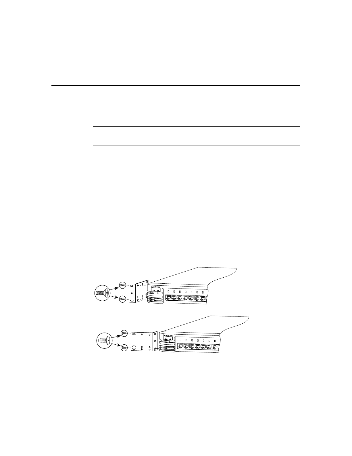
Figure 2-1 Attaching Brackets for 19- and 24-inch Racks (Front Panel Forward)
Phillips
flat-head
screws
RPS
1x 2x 3x 4x 5x 6x 7x 8x
MODE
19" configuration
Phillips
truss-head
screws
RPS
1x 2x 3x 4x 5x 6x 7x 8x
MODE
24" configuration
FastHub 400 10/100 Series Installation and Configuration Guide
H10730
H10731
Page 9

Attaching the Brackets to the Hub
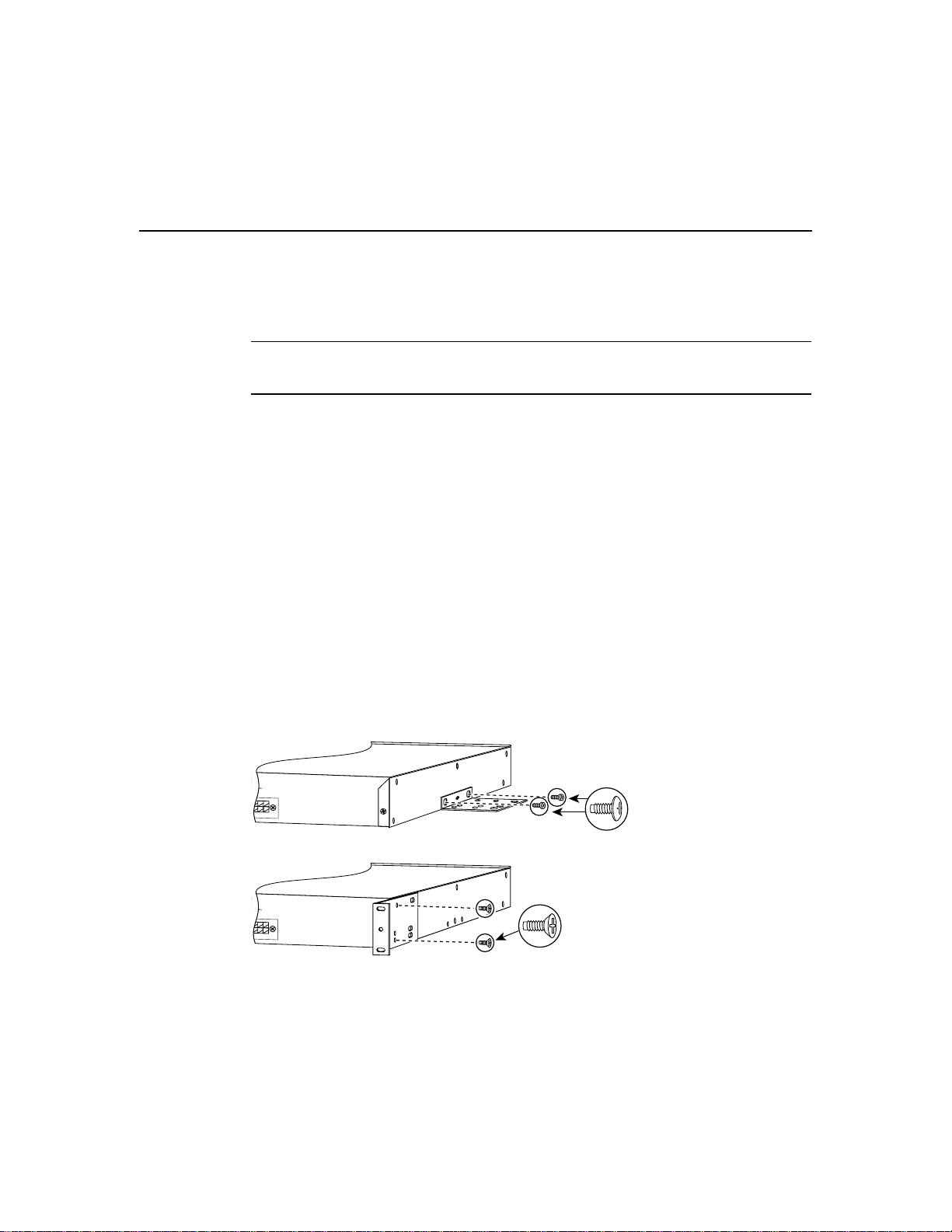
Figure 2-2 Attaching Brackets for 19- and 24-inch Racks (Rear Panel Forward)
R REMOTE
UPPLY
MANUAL
12V
@
R REMOTE
UPPLY
N MANUAL
12V
1A
@
1A
19" configuration
Phillips
flat-head
screws
H10186
Phillips
truss-head
screws
24" configuration
H10187
Figure 2-3 Attaching Brackets for 19- and 24-inch Racks (Mid-Mount)
R REMOTE
UPPLY
N MANUAL
12V
R REMOTE
UPPLY
N MANUAL
12V
@
1A
@
1A
19" configuration
24" configuration
Phillips
flat-head
screws
H10190
Phillips
truss-head
screws
H10191
Installing and Starting Up the Hub 2-9
Page 10

Installing the Hub in a Rack
Attaching the Hub to the Rack
After the brackets are attached, use two of the Phillips machine screws to securely attach
each bracket to the rack, as shown in Figure 2-4.
Figure 2-4 Attaching the Hub to a Rack (Front Panel Forward)
RPS
1x 2x 3x 4x 5x 6x 7x 8x 9x 10x 11x 12x 13x 14x 15x 16x 17x 18x 19x 20x 21x 22x 23x 24x
MODE
Phillips machine
screws
Ax Bx
SERIES
H10559
2-10
FastHub 400 10/100 Series Installation and Configuration Guide
Page 11

Attaching the Cable Guide to the Bracket
Attaching the Cable Guide to the Bracket
Attaching the cableguideandsecuringthecablesinthecableguide prevent the cables from
obscuring the hub and other devices in the rack. If the hub is in a 19- or 24-inch rack, you
can attach the cable guide to the left or right rack-mount bracket with the black screw, as
shown in Figure 2-5.
Figure 2-5 Attaching a Cable Guide
RPS
1x 2x 3x 4x 5x 6x 7x 8x 9x 10x 11x 12x 13x 14x 15x 16x 17x 18x 19x 20x 21x 22x 23x 24x
MODE
Ax Bx
SERIES
H10560
Black Philips machine screw
After the hub is in the rack, connect one end of the AC power cord to the AC power
connector on the hub and the other end of the cord to a power outlet. If your configuration
has a Cisco RPS, see the RPS documentation. After power is connected, the hub starts the
series of self-tests described in the “Powering Up the Hub and Running POST” section on
page 2-6.
Installing and Starting Up the Hub 2-11
Page 12
Installing the Hub on a Wall
Installing the Hub on a Wall
This section describes how to attach the hub in parallel and vertically to a wall.
Note Be sure the hub is powered off and is not connected to a power source before you
perform the steps in the sections that follow.
Attaching the Brackets to the Hub
The bracket orientation depends on whether you plan to parallel or vertical wall-mount the
hub:
• For a parallel wall-mount, use the Phillips truss-head screws to attach the short side of
the bracket to the hub.
• For a vertical wall-mount, use the Phillips flat-head screws to attach the long side of the
bracket to the hub.
Place the hub on a level surface, and use two of the Phillips truss-head or flat-head screws
to attach a mounting bracket to each side of the hub.
Figure 2-6 shows how to attach one bracket to one side of the hub. Follow the same steps
for the opposite side of the hub.
2-12
Figure 2-6 Attaching Brackets for Parallel and Vertical Wall-Mounting
R REMOTE
UPPLY
N MANUAL
12V
@
1A
For parallel wall-mounting
R REMOTE
UPPLY
MANUAL
12V
@
1A
Phillips
flat-head
screws
For vertical wall-mounting
FastHub 400 10/100 Series Installation and Configuration Guide
Phillips
truss-head
screws
H10210
H10211
Page 13

Attaching the Hub to a Wall
For the best support of the hub and cables, make sure the hub is securely attached to a wall
stud or to a firmly attached plywood mounting backboard, as shown in Figure 2-7. You
must supply your own screws to attach the hub to the wall.
Note If you plan to use the optional switched uplink module, install it in the hub before
vertically attaching the hub to a wall.
Figure 2-7 Attaching the Hub to the Wall
User-supplied
screws
Parallel wall-mount
Attaching the Hub to a Wall
Vertical
wall stud
H10189
Bx
Ax
24x
23x
22x
21x
20x
19x
18x
17x
16 x
15x
14x
13x
12x
11x
10x
9x
8x
7x
6x
5x
4x
3x
2x
1x
MODE
RPS
H10188
Vertical wall-mount
SERIES
Ax Bx
1x 2x 3x 4x 5x 6x 7x 8x 9x 10x 11x 12x 13x 14x 15x 16x 17x 18x 19x 20x 21x 22x 23x 24x
RPS
MODE
User-supplied
screws
After the hubisattachedtothewall,connect one end of the AC powercord to the AC power
connector on the hub and the other end of the cord to a power outlet. If your configuration
has a Cisco RPS, see the RPS documentation. After power is connected, the hub starts the
series of self-tests described in the “Powering Up the Hub and Running POST” section on
page 2-6.
Installing and Starting Up the Hub 2-13
Page 14

Connecting to the Console Port (FastHub 400M Models)
Connecting to the Console Port (FastHub 400M Models)
To connect the RJ-45 console port of a FastHub 400M model to a management station or
modem, you must use the supplied RJ-45-to-RJ-45 rollover console cable and the
appropriate adapter and follow these steps.
Note The rollover console cable and a RJ-45-to-DB-9 female DTE adapter are supplied
with the hub. If your management station requires a different adapter—such as a
RJ-45-to-DB-25 female DTE or RJ-45-to-DB-25 male DCE adapter—you must provide it.
Step 1 Configure the hub console port settings to match the management station or
modem. These are the default settings of the console port:
• 9600 baud
• 8 data bits
• 1 stop bit
• No parity
• No flow control
2-14
You can change the console port characteristics of the hub from the web-based
System Configuration Page (see the “Changing the System Configuration”
section on page 3-40) or by using the terminal command from the CLI.
Note Make sure the settings of the console port and the management station or
the modem match.
FastHub 400 10/100 Series Installation and Configuration Guide
Page 15

Connecting to the Console Port (FastHub 400M Models)
Step 2 Connect one end of the supplied rollover console cable to the console port, as
shown in Figure 2-8.
Caution Do not connect an actual telephone line, an ISDN line, or an Ethernet cable to
this console port. Damage to the hub can result. Make sure you use the supplied
RJ-45-to-RJ-45 rollover cable and adapters to connect the console port to the management
station or modem.
Figure 2-8 Connecting to the Console Port
DC INPUTS FOR REMOTE
POWER SUPPLY
UP
RATING
100-127 / 200-240 V~
2A /1A 50 / 60 Hz
CONSOLE
Supplied RJ-45-to-RJ-45
rollover console cable
SPECIFIED IN MANUAL
+5V
@
6A, +12V
@
1A
DC INPUT
DOWN
MEDIA MODULE
14256
Step 3
Attach the appropriate adapter,such as the supplied RJ-45-to-DB-9 female DTE
adapter (labeled Terminal), to a management station or modem.
Note If you are connecting the hub to a Sun workstation (or to a management
station with a female DB-25 serial connector), use a male-to-male gender
changer to attach the supplied RJ-45-to-RJ-45 rollover cable and a
RJ-45-to-DB-25 female DTE adapter to the management station.
Step 4 Connect the other end of the supplied rollover cable to the adapter.
Connector and cabling specifications for the console port are in the Appendix B,
“Connector and Cable Specifications.”
Now that the hub is connected to a management station, you can assign IP information to
the hub (see the “AssigningIP Information to the Hub (FastHub400M Models)” section on
page 2-16).
Installing and Starting Up the Hub 2-15
Page 16

Assigning IP Information to the Hub (FastHub 400M Models)
Assigning IP Information to the Hub (FastHub 400M
Models)
After you install the hub and connect it to a management station, you can assign IP
information to the hub. IP information identifies the hub to the network and is required to
manage and monitor the hub through the FastHub 400 series Hub Manager, the CLI, or
SNMP.
You can assign IP information to the hub by following the hub start-up prompts displayed
from a terminal emulation program on your management station.
You should contact your system administrator for the following information:
• Hub IP address
• Subnet mask (netmask)
• Default gateway (router)
To assign IP information to the hub, follow these steps:
Step 1 From your management station, start the terminal emulation program.
After POST completes, the Continue with configuration dialog? prompt appears
on the management station, and you can then follow the prompts to assign IP
information to the hub.
2-16
Step 2 From the terminal or PC, enter Y:
Continue with configuration dialog? [yes/no]: Y
Step 3 Enter the IP address (for example: 10.1.105.20):
Enter IP address: 10.1.105.20
Step 4 Enter the subnet mask (IP netmask) (for example: 255.255.255.0):
Enter IP netmask: 255.255.255.0
FastHub 400 10/100 Series Installation and Configuration Guide
Page 17

Assigning IP Information to the Hub (FastHub 400M Models)
Step 5 Enter the IP address of the default gateway (for example: 10.1.105.254):
Enter IP default gateway: 10.1.105.254
Note If the management station from which the FastHub 400 series Hub
Manager is used is not on the same IP subnet as the hub, you must also assign a
default gateway (the router for the local subnet).
The following information is displayed:
The following configuration command script was created:
ip address 10.1.105.20 255.255.255.0
ip default-gateway 10.1.105.254
!
end
Step 6 Enter Y:
Use this configuration? [yes/no]: Y
The following information is displayed:
Building configuration...
Use the enabled mode ‘configuration’ command to modify this
configuration.
Press RETURN to get started.
Pressing Return opens a CLI session.
Step 7 Exit from the terminal session.
You can now use the hub with its default values or configure and monitor it by using the
FastHub 400 series Hub Manager, the CLI, or SNMP and the MIB files.
Installing and Starting Up the Hub 2-17
Page 18

Connecting to the 10/100 Network Ports and Uplink Port
Connecting to the 10/100 Network Ports and Uplink Port
You can connect the 10/100 network ports and the uplink port to the ports on any 10BaseT
or 100BaseTX network device, such as workstations, servers, switches, routers, and other
hubs.
The 10/100 network ports (ports 1x through 12x or 1x through 24x) are internally crossed.
These ports require a crossover cable to connect to another hub or switch (unless you are
connecting to the uplink port on another FastHub or device). When connecting to a
workstation, server, or router, these ports require a straight-through cable.
The 10/100 uplink port (port 12 or 24) is not internally crossed and requires a
straight-through cable to connect to a server, hub, switch, or router.
By default, each 10/100 port on the hub configures itself to operate at the speed of the port
to which it is connected. If the port on the attached devicedoesnotsupportautonegotiation,
you can explicitly set the 10/100 port to match the speed of the attached port by using one
of the management interfaces available to the FastHub 400M models.
When connecting other network devices to the 10/100 ports, keep the following guidelines
in mind:
• Use the following types of twisted-pair cables when connecting the 10/100 network
ports or the 10/100 uplink port to a network device:
2-18
— 10BaseT network devices—Category 3, 4, or 5
— 100BaseTX network devices—Category 5
Note Althoughyoucanuse Category 3 and 4 cablesfor10BaseTnetworks,these cable
types will not work for 100BaseTX network devices. When designing a network that
includes autosensing repeaters like the FastHub 400 models, keep in mind that
100BaseTX traffic cannot be sent over these cable types.
• Use a straight-through cable to connect two ports when one of the ports is designated
with an X. Use a crossover cable to connect two ports when both ports are designated
with an X.
FastHub 400 10/100 Series Installation and Configuration Guide
Page 19

Connecting to the 10/100 Network Ports and Uplink Port
• Connectingtodevicesthat do notautonegotiateor that havetheirspeed setting manually
set can reduce performance or result in no link. To maximize performance, choose one
of these methods for configuring the 10/100 ports:
— Let both ports autonegotiate port speed.
— Manually set the same speed setting for the ports on both ends of the connection.
• When a 10/100 device connected to the hub changes speeds (from 10 to 100 Mbps or
from 100 to 10 Mbps), the device must reboot. The device then drops the link to the hub
and recreates the link after rebooting. (If the device does not reboot after changing
speeds, the hub does not detect the change in speed.)
Caution If you connect to ports 12x and 12 (or ports 24x and 24), you will disable both
ports.
Follow these steps to connect to 10BaseT or 100BaseTX devices:
Step 1 Connect one end of the Ethernet cable to a 10/100 port on the hub, as shown in
Figure 2-9.
Note When connecting the hub to workstations, servers, and routers, ensure
that the cable is a straight-through, twisted-pair cable. When connecting the hub
to switches or repeaters, use a crossover cable.
Figure 2-9 Connecting to a 10/100 Port
RPS
1x 2x 3x 4x 5x 6x 7x 8x
MODE
Category 5 cable
(not supplied)
10BaseT/100BaseTx
9x 10x 11x 12x 13x 14x 15x 16x
17x 18x 19x 20x 22x 23x 24x
21x
24
14514
Installing and Starting Up the Hub 2-19
Page 20

Accessing the Management Interfaces (FastHub 400M Models)
Step 2 Connect the other end of the cable to the 10BaseT or 100BaseTX port of the
network device.
Step 3 Check to see that the port LED for the port that you connected in Step 1 comes
on.
If the port LED does not come on, check for the following problems:
• The network device is not turned on.
• The Ethernet adapter in the network device is not operating correctly.
• You are using the wrong type of Ethernet cable.
• The Ethernet cable is damaged or not connected correctly.
Step 4 If required, reconfigure and reboot the connected network device.
Step 5 Repeat Steps 1 through 3 for each device that you are connecting to the hub.
If you need more information about Ethernet cabling and 10/100 port pinouts, refer to
Appendix B, “Connector and Cable Specifications.”
Accessing the Management Interfaces (FastHub 400M
Models)
2-20
FastHub 400 10/100 Series Installation and Configuration Guide
After you assign IP information to the hub, you can access the hub management interfaces.
This section provides information for accessing the FastHub 400 series Hub Manager, the
CLI, and SNMP and MIB files.
Page 21

Accessing the FastHub 400 Series Hub Manager
Accessing the FastHub 400 Series Hub Manager
To access the hub manager, all you need is the IP information of the hub (and the password
if one has been assigned). IP information for the hub is usually assigned when the hub is
first started up after installation. (See the “Assigning IP Information to the Hub (FastHub
400M Models)” section on page 2-16.)
Note You can access the hub manager from a PC connected to one of the 10/100 ports.
Therefore, make sure that you do not disable or otherwise misconfigure the port through
which you are communicating with the hub. Youmightwanttowrite downtheport number
to which you are connected. Make changes to the hub IP information with care.
To access the hub manager, follow these steps:
Step 1 Start Netscape Communicator (4.03 or higher) or Microsoft Internet Explorer
(4.01 or higher).
Step 2 Ensure that the following browser features are enabled:
• Java
• JavaScript
• Set the caching of pages to Every time in Communicator or
Every visit to the page in Internet Explorer.
Step 3 Enter the IP address of the hub in the Location field if you are using
Communicator (the Address field if you are using Internet Explorer) to display
the hub manager Home Page (Figure 2-10).
Installing and Starting Up the Hub 2-21
11187
Page 22

Accessing the Management Interfaces (FastHub 400M Models)
Figure 2-10 Home Page
Click Apply after
making changes
on a page.
Click Revert
to discard
unapplied
changes on
a page.
Click Help for
procedures and
detailed field
descriptions.
Click the Mode
button to change
the mode that
the LEDs display
for the fixed
10/100 ports.
HOME PORT GROUP IP SNMP CDP SYSTEM
Click to display the settings, status, and
statistics of an installed 10BaseT/100BaseTX
or 100BaseFX switched uplink module.
Click these topics to move from page
to page. On Netscape Communicator
only, when the cursor is above a topic,
a pop-up briefly describes the options
on that particular page.
Click a port to display its
settings, status, and statistics.
Shows when another hub is connected to a
stacking connector on the hub rear panel.
Note You can bookmark the hub IP address to retrieve the hub manager for later use. If
you are using Communicator, choose the Communicator menu option, and select
Bookmarks > Add Bookmark. If you are using Internet Explorer, choose the Favorites
menu option, and select Add to Favorites.Do not use the right mouse button to bookmark
the hub IP address; doing so only saves the specific frame (image) of the hub manager page.
15529
2-22
FastHub 400 10/100 Series Installation and Configuration Guide
Page 23

Accessing the CLI
You can access the CLI
• From a console terminal connected to the hub console port. For more information, see
the “Connecting to the Console Port (FastHub 400M Models)” section on page 2-14.
• Through a Telnet session from a remote host by entering the telnet command and the
name or IP address of the hub.
• Through a Telnet session by clicking Telnet on the hub manager Home Page.
When you access the CLI and a password has been defined, the following prompt is
displayed:
Cisco Systems Console
Enter Password:
Enter the password. The hostname> prompt is displayed after you enter the correct
password.
For complete information about the CLI, refer to the FastHub 400 10/100 Series Command
Reference.
Accessing the CLI
Accessing the MIB Files through SNMP
Youcan access the hub MIBfilesthroughSNMP.The following MIBfilescontainvariables
that can be set or read to provide information about the hub and the traps generated by the
hub.
• RFC1213-MIB.my contains the MIB II (RFC 1213).
• ETHERLIKE-MIB.my contains the Ethernet Transmission MIB (RFC 1643).
• CISCO-CDP-MIB.my contains the CDP MIB.
• SNMP-REPEATER-MIB.my contains the standard MIB for managing the hub.
• RMON-MIB.my contains the RFC 1757 RMON (Groups 1, 2, 3, and 9). More
information about RMON and the RMON groups is provided in the “Remote
Monitoring” section on page 2-25.
• CISCO-SIBU-SIMPLE-UPGRADE-MIB.my contains the MIB module for upgrading
the firmware on Cisco low-end devices.
Installing and Starting Up the Hub 2-23
Page 24

Accessing the Management Interfaces (FastHub 400M Models)
• CISCO-SIBU-MANAGERS-MIB.my contains the MIB module for management
interfaces on the FastHub 400M models.
• CISCO-SIBU-STACKABLE-DUAL-SPEED-HUB-MIB.mycontains the MIB module
that extends the REPEATER-MIB to manage Cisco low-end stackable repeater
products.
If you are going to manage the hub by using SNMP and the MIB files, the Read and Write
community strings need to be set. To do this, you can either
• Use the default community strings
— Read community string. The default is public.
— Write community string. The default is private.
• Assign community strings by using the SNMP Management Page or by using the
snmp-server community command on the CLI.
Note Wait approximately 30 seconds for the changes to be saved to permanent storage
before turning off the hub, or the changes might not be saved.
You can obtain a copy of the MIB files in the following ways:
• Using File Transfer Protocol (FTP) to access the ftp.cisco.com server.
• Using Cisco Connection Online (CCO) to access the cisco.com server.
Using FTP to Access the MIB Files
To obtain a MIB file, follow these steps:
Step 1 Use FTP to access the server ftp.cisco.com.
Step 2 Log in with the username anonymous.
Step 3 Enter your e-mail name when prompted for the password.
Step 4 At the ftp> prompt, change directories to /pub/MIBs.
Step 5 Use the get README command to display the readme file listing available
files.
Step 6 Use the get MIB_filename command to get a copy of the MIB file.
2-24
FastHub 400 10/100 Series Installation and Configuration Guide
Page 25

Using CCO to Access the MIB Files
To access the MIB files from CCO, click Software & Support to display the Software
Center site.
CCO serves a wide variety of users through two interfaces that are updated and enhanced
simultaneously: a character-based version and a multimedia version that resides on the
World Wide Web (WWW). The character-based CCO supports Zmodem, Kermit,
Xmodem, FTP, and Internet e-mail, and it is excellent for quick access to information over
lower bandwidths. The WWW version of CCO provides richly formatted documents with
photographs, figures, graphics, and video, as well as hyperlinks to related information.
You can access CCO in the following ways:
• WWW: http://www.cisco.com
• WWW: http://www-europe.cisco.com
• WWW: http://www-china.cisco.com
• Telnet: cco.cisco.com
• Modem: From North America, 408 526-8070; from Europe, 33 1 64 46 40 82. Use the
following terminal settings: VT100 emulation; data bits: 8; parity: none; stop bits: 1;
and connection rates up to 28.8 kbps.
Accessing the MIB Files through SNMP
Foracopy of CCO’sFrequently Asked Questions (FAQ),contact cco-help@cisco.com. For
additional information, contact cco-team@cisco.com.
Remote Monitoring
The Remote Monitoring (RMON) MIB is used by network managers to monitor remote
devices. An RMON implementation consists of a software probe that continually collects
statistics about a LAN and a management station that communicates with the probe. The
probe transfers information to the management station on request or when a predefined
threshold is crossed.
The hub supports four RMON groups (Table 2-1) as defined in RFC 1757. Default statistic
rowsarecreated for each port when you start the hub. You can obtain information about the
four supported groups by using any SNMP management application.
Installing and Starting Up the Hub 2-25
Page 26

Where to Go Next
Table 2-1 RMON Groups and Their Functions
Group Name Description
Statistics This group collects traffic and error statistics for a specific interface. For
example, you could use this group to determine how many error packets have
been seen on a given port.
Statistics from this group can be used by the history group to record historical
views of network performance. A statistics row is established by default for
each hub port.
History This group periodically samples the counters generated by the statistics
group. This information can be used to establish baseline information
regarding network activity. You can define the intervals you want to record
information for, and you can define how many of the samples are to be stored.
Note RMON statistics gathering has a maximum limit of 50 history buckets
per historyControlTable entry.
Alarm This group generates alarms according to user-defined thresholds. You could,
for example, configure RMON to generate an alarm when alignment errors on
a port exceeded a predefined limit. Rising and falling thresholds can be
defined, and the events group can generate traps and automated responses
based on the alarms.
Event This group sends traps to the management station based on information
(alarms) received from the alarm group.
Where to Go Next
Now that you have installed the hub and, if you have a FastHub 400M models, assigned IP
information to the hub, you can continue to
• Chapter 3, “Configuring and Monitoring from the Hub Manager” for configuration and
monitoring information. (FastHub 400M models only).
• Appendix C, “FastHub Stacks” for interconnecting the hub to other FastHub 400M
models to form hub stacks.
• Appendix D, “Switched Uplink Modules” for descriptions of the optional switched
uplink modules and procedures for installing and connecting to them.
2-26
FastHub 400 10/100 Series Installation and Configuration Guide
 Loading...